ChargePoint Gateway Installation
- If the charging station is not installed, commissioned, or serviced by a ChargePoint certified technician using a ChargePoint-approved method, it is excluded from all ChargePoint and other warranties and ChargePoint is not responsible.
- You must be a licensed electrician and complete training at https://www.chargepoint.com/partners/training-certification to become ChargePoint certified and to access ChargePoint's web-based installer tools or ChargePoint Installer app.
A ChargePoint Gateway for Europe (CPGW![]() ChargePoint Gateway-EU) consists of a cellular modem for wide area networking, and built-in Wi-Fi
ChargePoint Gateway-EU) consists of a cellular modem for wide area networking, and built-in Wi-Fi![]() Wireless Fidelity for local communications to and from CPF32 charging stations.
Wireless Fidelity for local communications to and from CPF32 charging stations.
ChargePoint Gateway Specifications
Basic specifications for the CPGW![]() ChargePoint Gateway-EU are shown in the table below.
ChargePoint Gateway-EU are shown in the table below.
|
Rating |
Class II |
|---|---|
|
Input Power |
< 4 W |
|
Input Current |
< 0.4 A for 100-240 VAC, 50-60 Hz |
|
Input Terminals |
100-240 VAC, universal |
|
Physical Placement |
0.6-1.2 m (2-4 ft) from CPF32 charging station(s) 1.8-2.4 m (6-8 ft) above floor level |
|
Connectivity |
Supports 1-9 CPF32 charging stations |
|
Connectivity Placement |
< 30.5-38 m (100-125 ft) line-of-sight to associated charging stations |
For detailed specifications, refer to the ChargePoint Gateway datasheet located at Product Reference Documentation.
Requirements
Before installing the ChargePoint Gateway, choose an appropriate location by considering the following:
-
Power must be available at the installation site.
-
All charging stations must be located within 30.5-38 m (100-125 ft) line-of-sight.
-
The Gateway relies on an external device for overcurrent protection. The installer must ensure the Gateway is protected by a maximum 20A branch circuit breaker.
-
The Gateway requires a surge protector device (SPD) or surge arrester as part of the installation to address transient over voltages exceeding Over voltage Category II, 2500 Vpk.
-
The Gateway must have a readily accessible disconnect device.
-
The location must receive consistently available 3G GSM cellular coverage. The signal strength should be better than -90db (for example, -85db is better than -90db). To ensure adequate signal strength in underground garages or other enclosed parking structures, cellular repeaters may be required.
Wi-Fi Wireless Fidelity signal strength between the ChargePoint Gateway and the charging stations is strong, and signals bend (diffract) around narrow columns with low signal loss. Avoid installations where concrete walls are located between the ChargePoint Gateway and the CPF32 charging stations. For maximum cellular coverage, mount the ChargePoint Gateway as high as possible.
-
It is recommended that you permanently install the ChargePoint Gateway by running service wiring into the bottom of the Gateway using region-appropriate wire routing, and attaching it to a wall using the supplied screws and wall anchors.
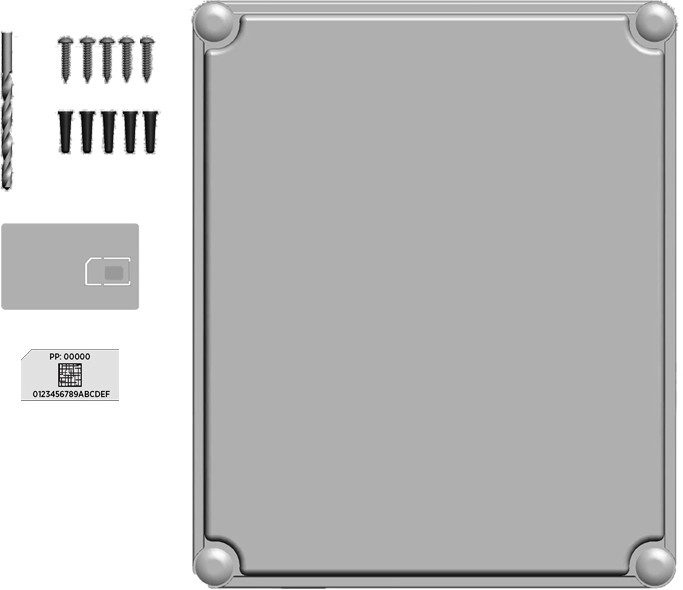
Contents of the Box
Listed below are the components in the box:
-
Main unit with cover (1)
-
1/4” drill bit (1)
-
#10 x 1” screws (5)
-
Wall anchors (5)
-
Compression gland (1)
-
Installation template (1) - inserted in the center of this installation guide
-
Spare activation label (1) - a duplicate label is attached to the inside of the main unit
Contractor Tools
-
Drill
-
Phillips screwdriver
-
Two adjustable wrenches to remove the internal nut when permanently hard-wiring
Installing the Gateway
Follow the steps below to install the ChargePoint Gateway at a permanent location.
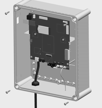
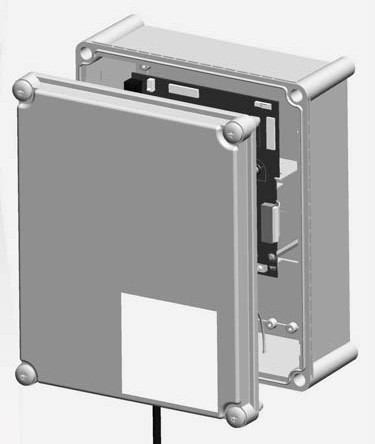
Mounting the Unit
-
Use the installation template to mark the location of the four mounting holes.
-
Drill the four mounting holes and insert the anchors.
-
Loosen the screws on the front of the ChargePoint Gateway to remove the front cover.
-
Align the main unit with the mounting holes and fasten using four of the supplied #10 x 1 in. screws and a Phillips screwdriver.
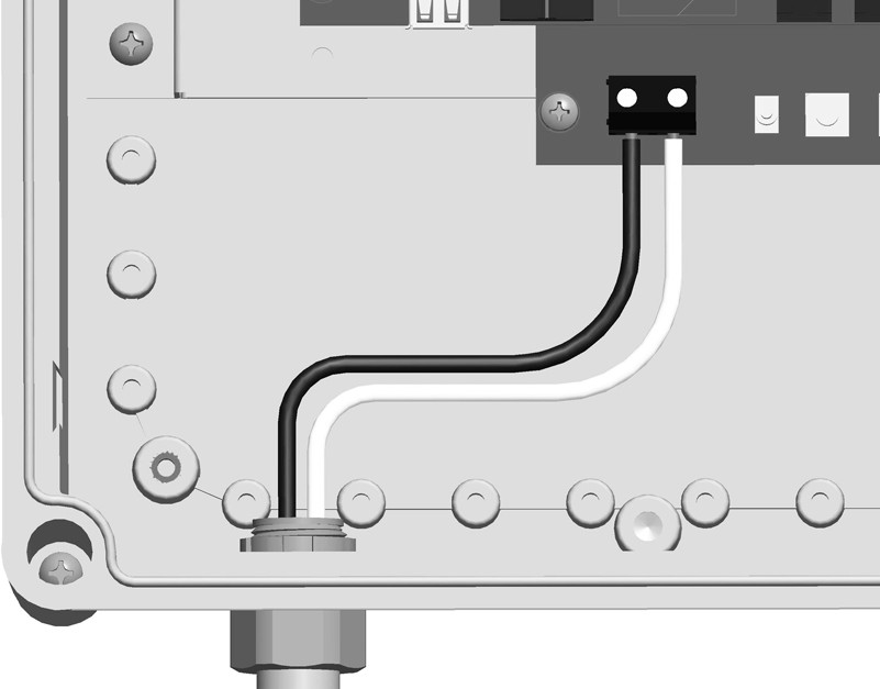
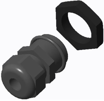
Installing the Supply Wiring
ChargePoint recommends hard-wiring the ChargePoint Gateway with electrical termination to the power source.
-
Using two wrenches, one on the inside and the other on the outside, remove the internal plastic nut.
-
Reference local electrical code to determine the appropriate cable for the supplied compression gland.
-
Using wire routing and fittings appropriate to local code, route the needed length of 6.0-2.5
mm2 (10-14 AWG
American Wire Gauge) stranded or solid service wiring to the ChargePoint Gateway through the compression gland, enclosure, and nut. -
Install cable connector ferrules onto service wires.
-
Strip service wires 6.4 mm (1/4 in).
-
Connect L1 and N service wiring as shown.
-
Torque the compression gland nut to 3.75 Nm (33.2 in-lb) to ensure the IP54 rating.
Installing the Cover
Align the cover to the front of the main unit and turn the screws to lock the cover into place.
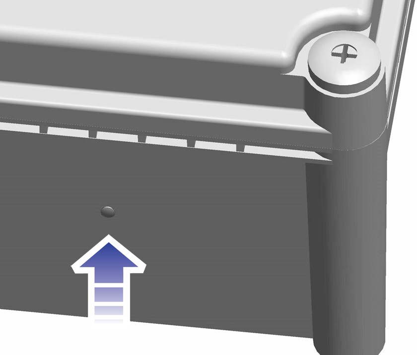
Powering On
Power on the ChargePoint Gateway by switching the service breaker ON.
As the ChargePoint Gateway powers on, the LED flashes yellow as it attempts to communicate with the cellular network. When cellular communication is established, the LED is solid yellow.
If the Gateway continues to flash yellow for an extended period, check the strength of the cellular signal at the installation location. You may need to strengthen the signal by installing cellular repeaters.
Configure Gateway
After completing the physical installation of the ChargePoint Gateway, you must prepare it for activation on the ChargePoint network by pinpointing its exact location.
Required Tools and Materials
|
|
Smartphone with Internet connectivity |
|
ChargePoint Installer app |
|
|
Exact location of stations or units, including parking space |
|
ChargePoint installer login credentials |
To complete the setup, you must have completed the ChargePoint Installer training and received your ChargePoint Installer login.
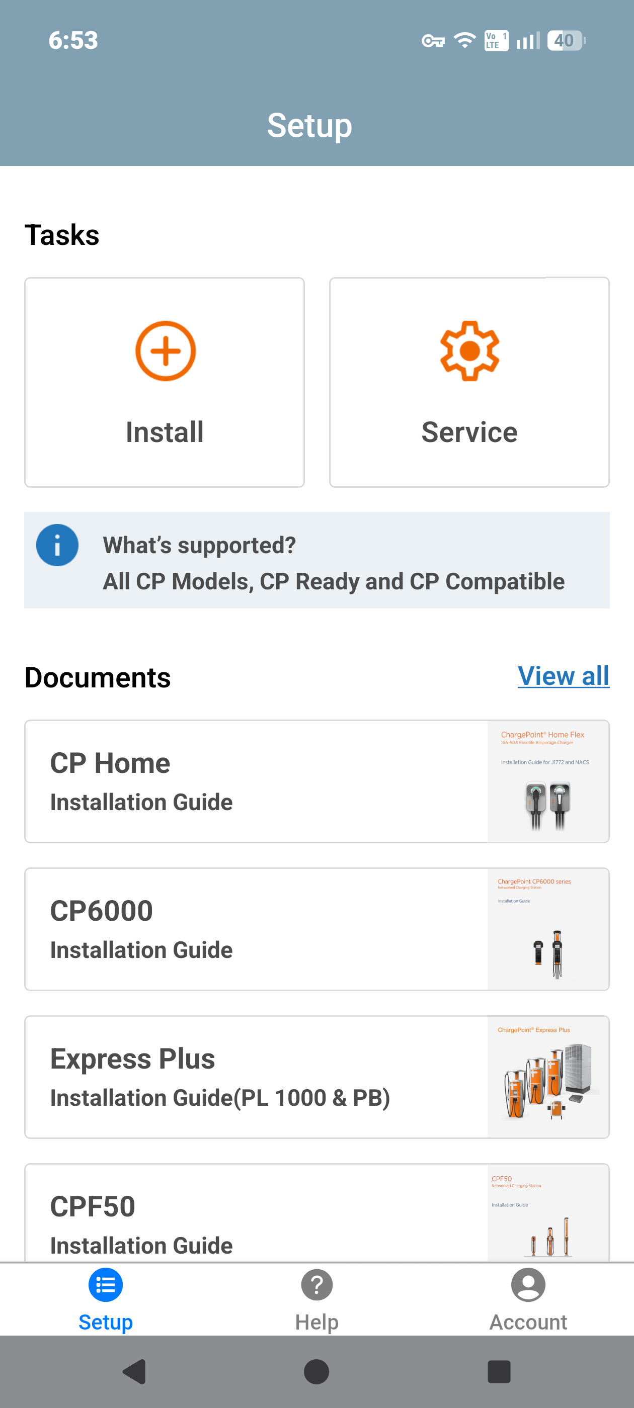
Pinpoint the Station
Open the ChargePoint Installer app on your smartphone and follow the instructions below:
-
If you do not already have the Installer app, scan the QR
Quick Response code to download the app.
-
Log in or register using the ChargePoint Installer app on your smartphone.
-
Tap on Install.
-
Use the app to scan the QR
Quick Response code on the charging station label.
-
The app automatically identifies the charging station and begins the pinpointing and configuration process.
-
Follow the in‑app instructions to complete pinpointing and configuration process.
Station Activation
As the installer, your role is to support this process by providing the station owner with the required station identification information. Before leaving the site, give the station owner a list of all installed station serial numbers and/or MAC![]() Message Authentication Code addresses and inform them that activation is required before the station can be used.
Message Authentication Code addresses and inform them that activation is required before the station can be used.
If station owner has additional questions, you can refer them to ChargePoint Support at chargepoint.com/support.
Complete the Post-Installation Checklist
To complete the Post-Installation Checklist, refer the ChargePoint Gateway Install Checklist document in Product Reference Documentation.
