Surface Conduit Entry Kit (SCEK)
The Surface Conduit Entry Kit (SCEK![]() Surface Conduit Entry Kit) is for Express Plus Power Link 1000 charging stations in situations where the site cannot run conductors underground or the site is not using stub-up entry through Concrete Mounting Template (CMT) embedded in a concrete pad. This SCE
Surface Conduit Entry Kit) is for Express Plus Power Link 1000 charging stations in situations where the site cannot run conductors underground or the site is not using stub-up entry through Concrete Mounting Template (CMT) embedded in a concrete pad. This SCE![]() Surface Conduit Entry kit is only for the pedestal mount variant of Power Link 1000.
Surface Conduit Entry kit is only for the pedestal mount variant of Power Link 1000.
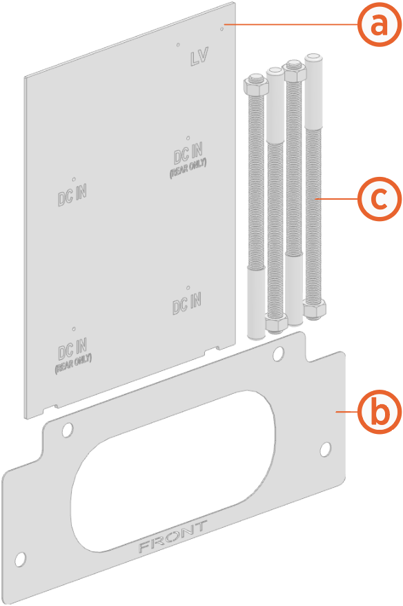
SCE Kit Contents
-
Template for marking and drilling conduit holes
-
Surface mount template for marking and drilling holes into concrete surface
-
M16 anchor bolts and nuts with protective caps (x4) for mounting Power Link 1000
Required Tools and Materials
-
Cut-resistant gloves
-
Protective eyewear
-
Marker
-
Vacuum
For Power Link 1000 Surface Mounting
-
Concrete drill with level feature recommended
-
25 mm (1 in) and 6 mm (1/4 in) concrete bits
-
24 mm (15/16 in) socket or open ended wrench
-
750 ml of epoxy with bonding strength of 11.7 MPa minimum, compressive strength of 82.7 MPa minimum, and tensile strength of 49.3 MPa minimum, such as Hilti HIT-RE 500 V3 (normal cure time), Hilti HY-200 (fast curing), or similar.
-
Paper towels
Different epoxy types have different cure times at various temperatures. Check local temperatures for the site in advance to help choose an appropriate epoxy.
For Surface Conduit Entry
-
Surface wireways:
Wiring
Maximum Conduit Trade Size
Conduit Body Type / Maximum Size
Quantity
DC input conductors
103 mm (4 in)
LB Type / 103 mm (4 in)
1 or 2
48 V DC and Cat6 Shielded Twisted Pair (STP
 Shielded Twisted Pair) Ethernet
21 mm (3/4 in)
LB Type / 21 mm (3/4 in)
1 or 2
The conduit body type LBs must fit within the rear clearance (i.e., 610 mm or 24 in) as specified in the Express Plus Installation.
-
Sheet metal hole saw with pilot bit for conduit sizes listed above
-
Cable puller or fish tape
-
Tools for cutting, assembling, and securing wireways
Install Anchor Bolts
To install anchor bolts, complete the following steps:
-
Refer to the site drawings and place surface mount template at the proposed location.
Make sure to leave enough clearance at the rear side (610 mm or 2 ft) for surface conduit entry and servicing. -
Use a marker to mark the locations for the anchor bolts and remove the surface mount template.

-
Use the 6 mm (0.25 in) concrete drill bit to drill a pilot hole about 51 mm (2 in) deep at each marked location. The holes must be parallel to each other and perpendicular to the surface.
-
Use the 25 mm (1 in) concrete drill bit to drill an anchor hole a minimum of 229 mm (9 in) deep. Anchor bolts must have 76 mm +/- 12.7 mm (3 in +/- 0.5 in) above surface.
 concrete drill bit to drill an anchor hole a minimum of 229 mm (9 in) deep. Anchor bolts must have 127 mm +/- 12.7 mm (5 in +/- 1/2 in) above surface.")
-
Use a vacuum to clean the concrete residue.

-
Place surface mount template on the surface again. Verify that the anchor holes align with the holes in the surface mount template.
-
Prepare the epoxy. Ensure the applicator is dispensing correctly mixed epoxy before beginning work (for example, the Hilti epoxy is white when unmixed and gray when mixed).
-
Fill the first anchor hole with epoxy until the epoxy is about 44.5 mm (1.75 in) from the top of the hole.
Continue immediately to the next step because the epoxy sets within about eight minutes. from the top of the hole.")
-
Insert anchor bolt into the hole. Rotate the anchor bolt as you insert it to draw epoxy into the threads. If needed, add more epoxy until it fills hole to surface level. Use paper towels to wipe off any excess.

-
Use a level to check that the anchor bolt is plumb. If needed, adjust it while the epoxy is still setting.

-
Measure the bolt exposed above the surface and it must be 76 mm (3 in).
.")
-
Repeat the above epoxy steps for each of the other three anchor bolts.
-
If Power Link 1000 station will not be immediately installed, insert protective caps over the anchor bolts.

-
Allow the epoxy to cure for the initial cure time listed on the epoxy usage instructions before beginning to install Power Link 1000.
Install Surface Conduit Entry
To install surface conduit entry, complete the following steps:
-
Before you begin, refer to the site drawings to find out from which side of the Power Link 1000 the wiring must enter from:
-
If the wiring needs to enter from left or right side, the two diagonally placed DC IN holes (b) must be used.
-
If the wiring needs to enter straight from rear side, the two lower DC IN holes (c) must be used.

-
Pilot holes for conduits to pull LV DC
Low Voltage Direct Current input wires and Ethernet cables -
Pilot holes for conduits to pull HV DC
High Voltage Direct Current input wires from left or right side -
Pilot holes for conduits to pull HV DC
High Voltage Direct Current input wires straight from rear side
-
-
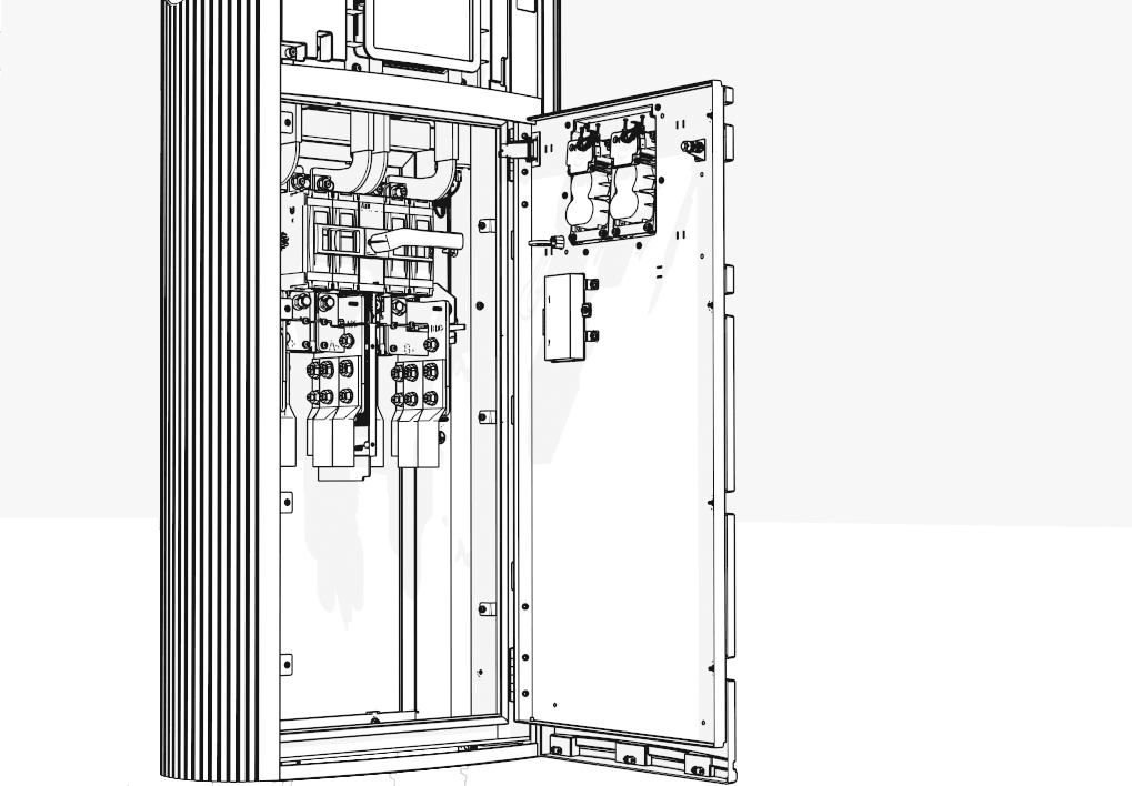
After mounting and securing Power Link 1000 onto the anchor bolts, open the lower door to access the lower cabinet (uninstall safety panel if present). See Power Link 1000 Installation Guide.
-
Place the SCE
Surface Conduit Entry template on the two lower tabs and lay it on the rear cover.Make sure to hold the SCE Surface Conduit Entry template firmly on the rear cover.

-
Use a marker to mark the pilot hole locations on the rear cover and remove the SCE
Surface Conduit Entry template. See instructions given to find out which pilot hole locations to mark.
-
Use a suitable hole saw, position the hole saw's pilot bit on the marked location, and drill a hole into the rear cover. Repeat for other marked locations.
The right side conduit entry illustrations shown below are for demonstration purposes only. Make sure to drill holes at suitable locations according to the instructions given .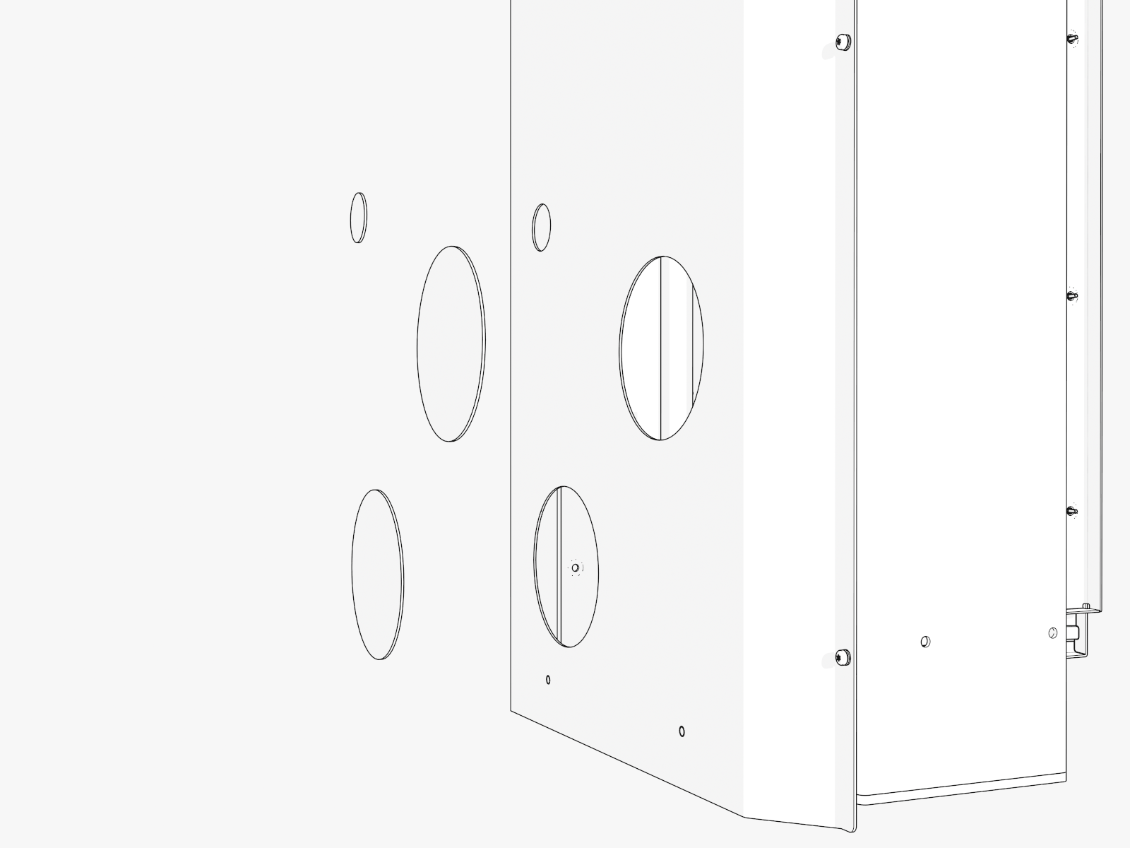
-
Vacuum all metal shavings.
-
Install suitable conduit bodies into the holes to pull wiring into Power Link 1000.

