Connect Wires
(Standard Pedestal)
- Before any procedure, disconnect the power.
- Follow local code and site lockout/tagout procedure to de-energize the station.
- Wait for energy to dissipate (approximately five minutes).
- Keep power off until all covers and panels are reinstalled and the work is complete.
Disconnect power at the site electrical panel.

Use a multimeter to test that the unit is de-energized.
-
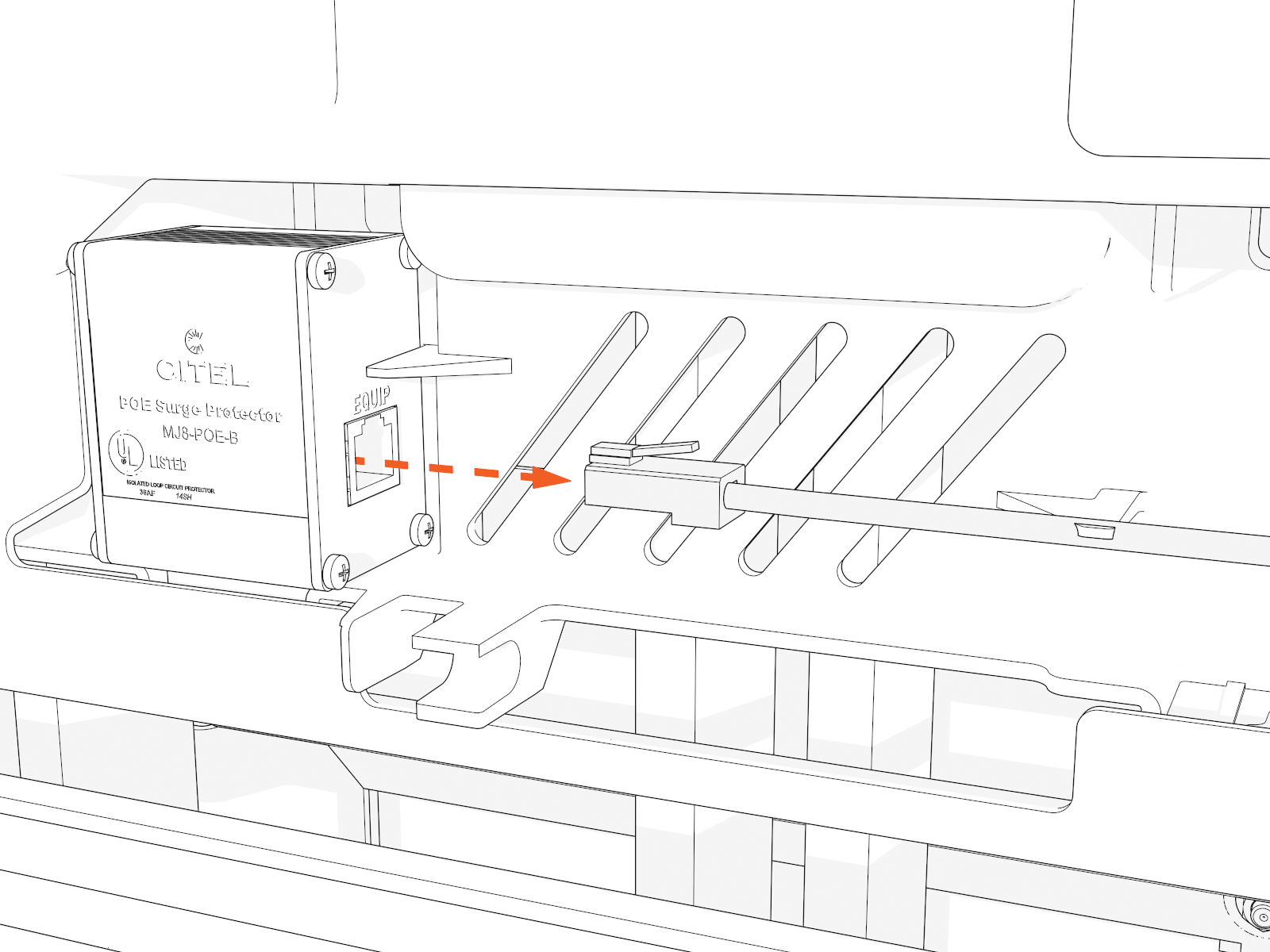
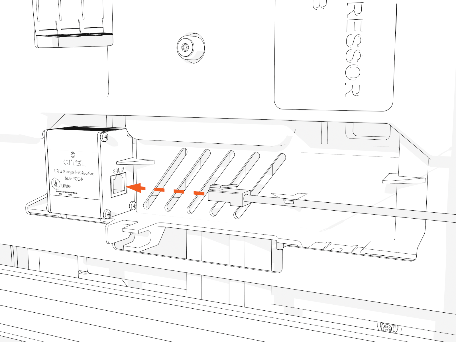
Disconnect the Ethernet cable from the Ethernet surge suppressor.
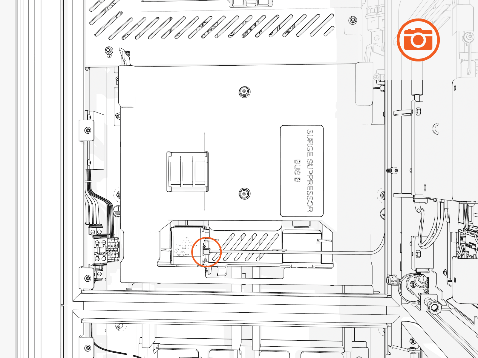
Take a photo or note to identify which port later.
-
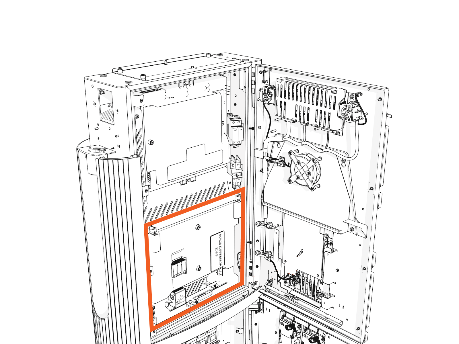
Access the upper bus bars.
-
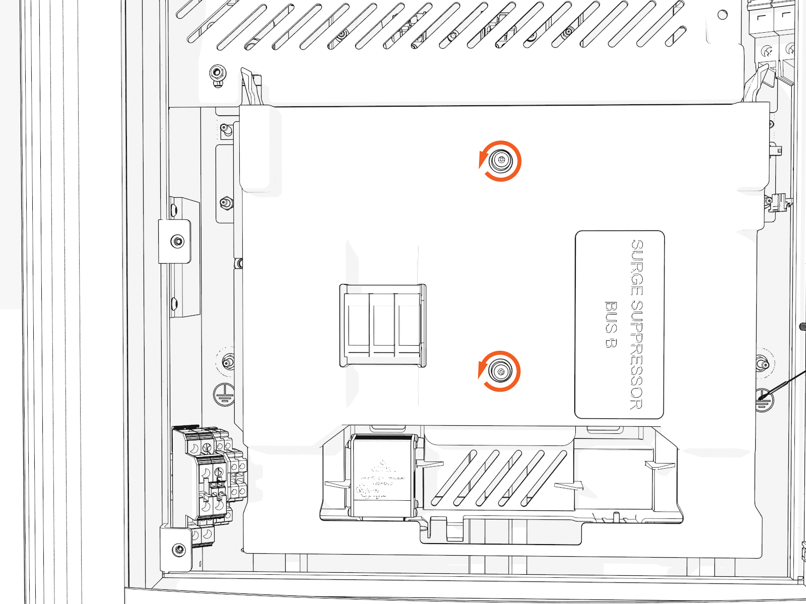
On the power plate cover, loosen the captive screws.
-
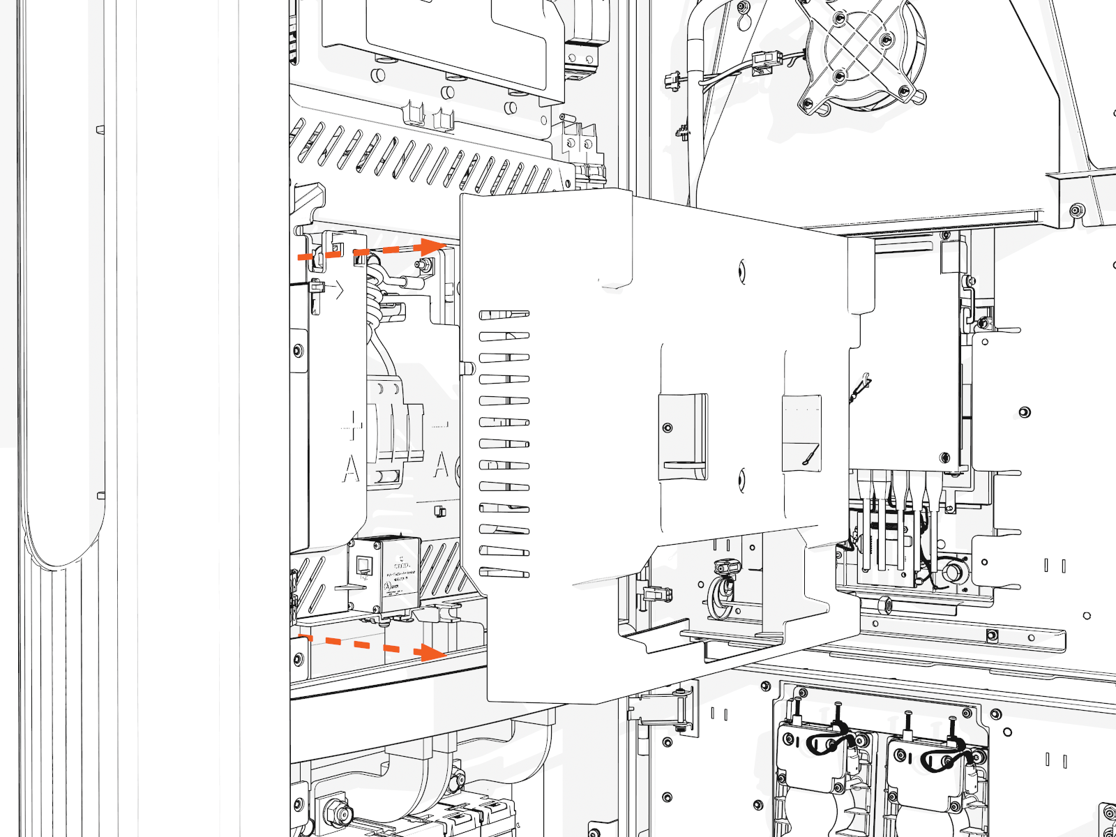
Remove the cover.
-
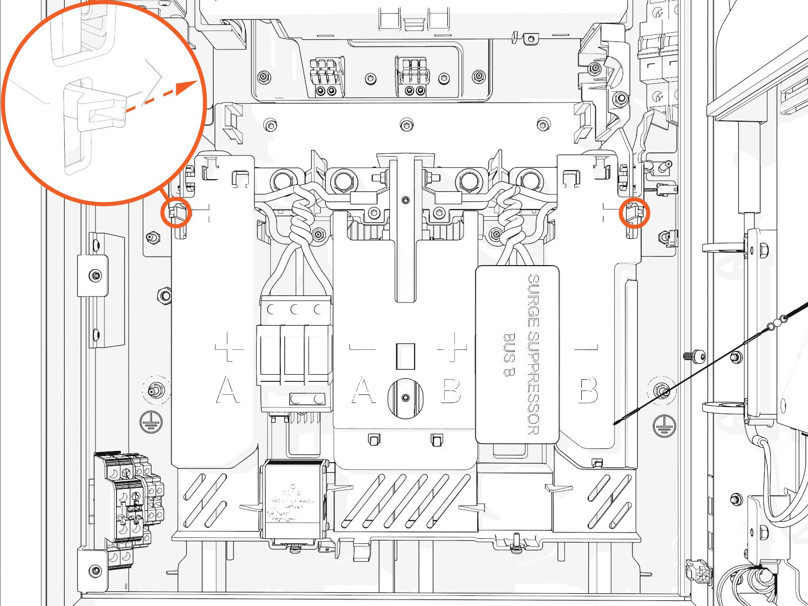
Release the tabs on the upper safety cover.
-
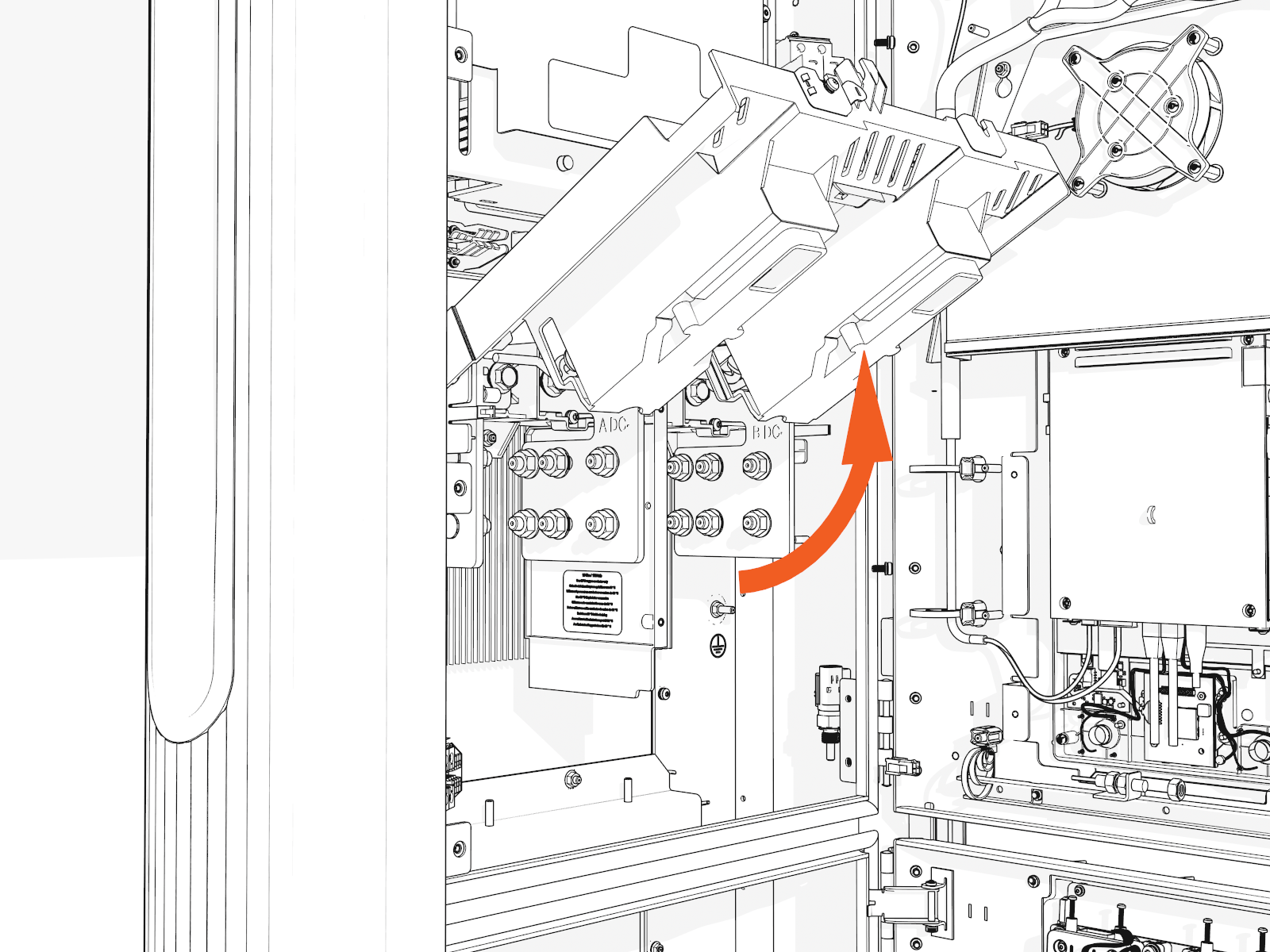
Lift up from the bottom until it locks in the open position.
Install DC Conductors and Lugs, and Ground Wire
-
Ensure you have de-energized the applicable circuit and locked out/tagged out the disconnect according to standard practice and local code before proceeding.
-
Use a multimeter to test that power is off.
-
Route all conductors into the correct area within the cabinet.
Measure and cut
-
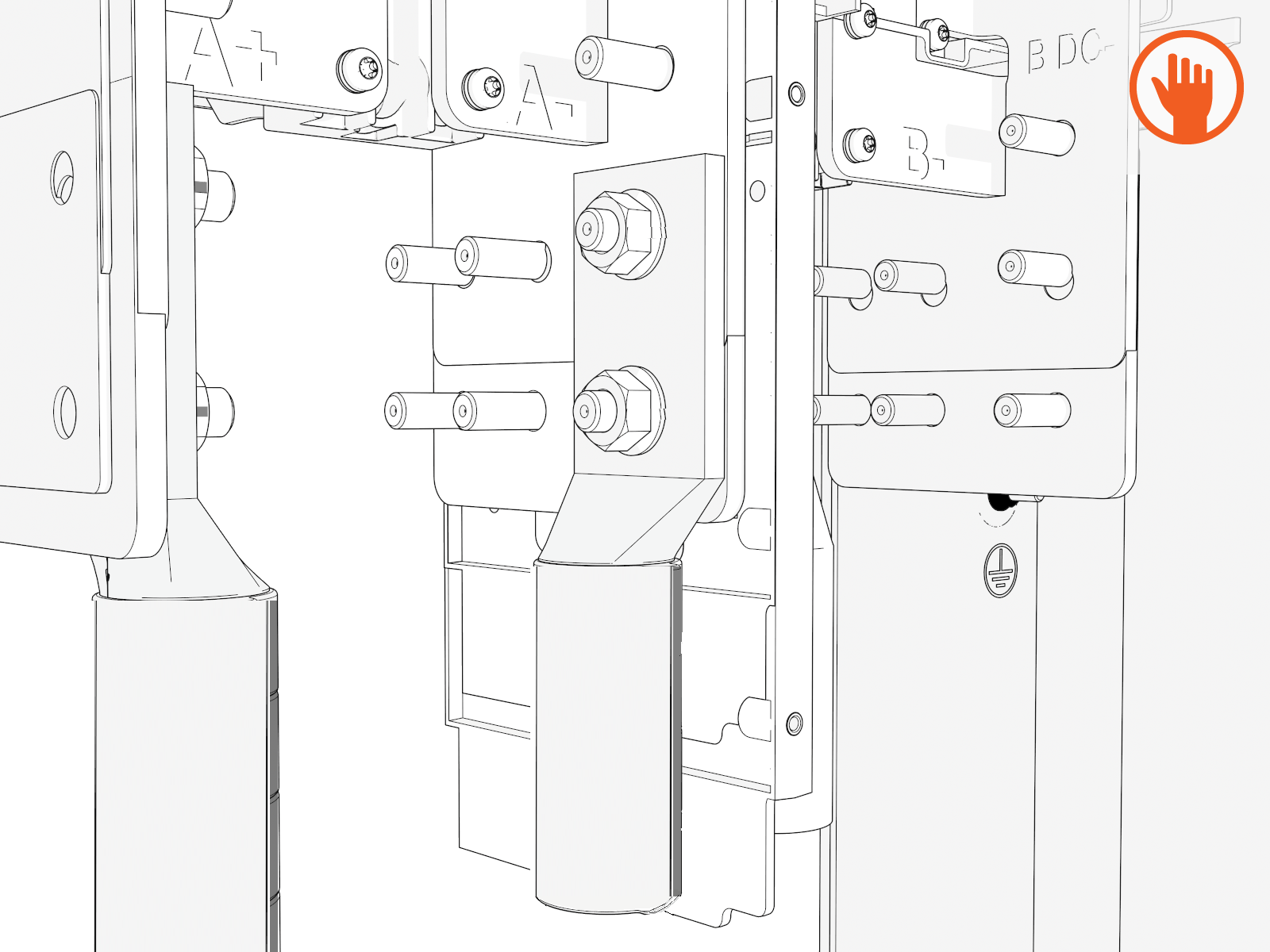
Loosely install lugs only (without the conductors) onto bus bars. Hand-tighten.
Use included bolts, washers, and nuts
-
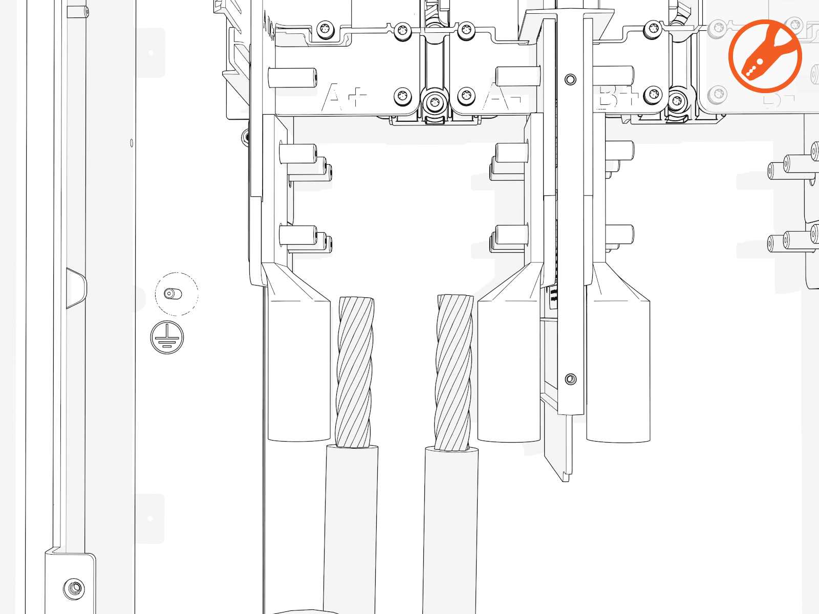
Measure the length from each conductor to its corresponding lug.
Mark each conductor at the point where you will need to trim it.
DC bus bars are marked in order from left to right:
Single Input Dual Input A+
A-
A+
A-
B+
B-
-
Strip and cut the conductors to the desired length.
Install DC lugs
-
Uninstall the lugs. Crimp a lug onto each conductor.
Use compression lugs with the specifications . Use the lug manufacturer’s tool and die. If required, heatshrink or tape the crimp area to meet local code.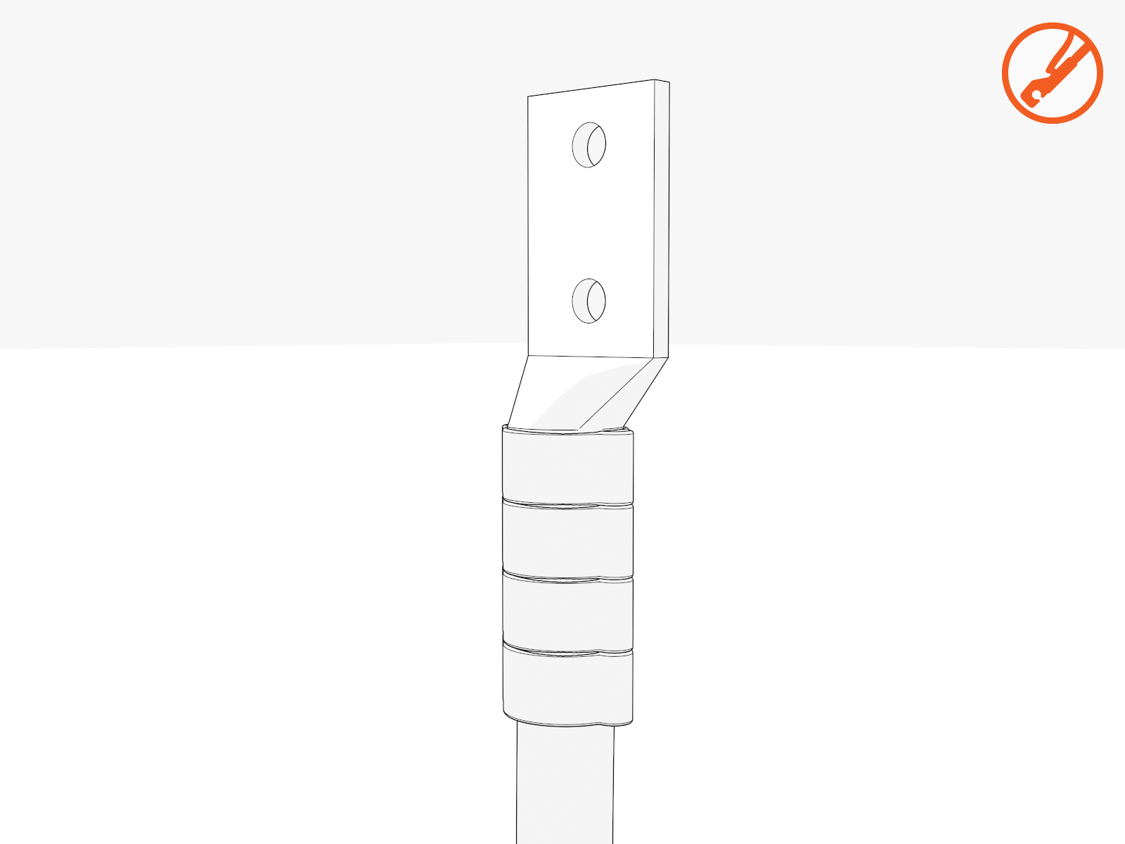
-
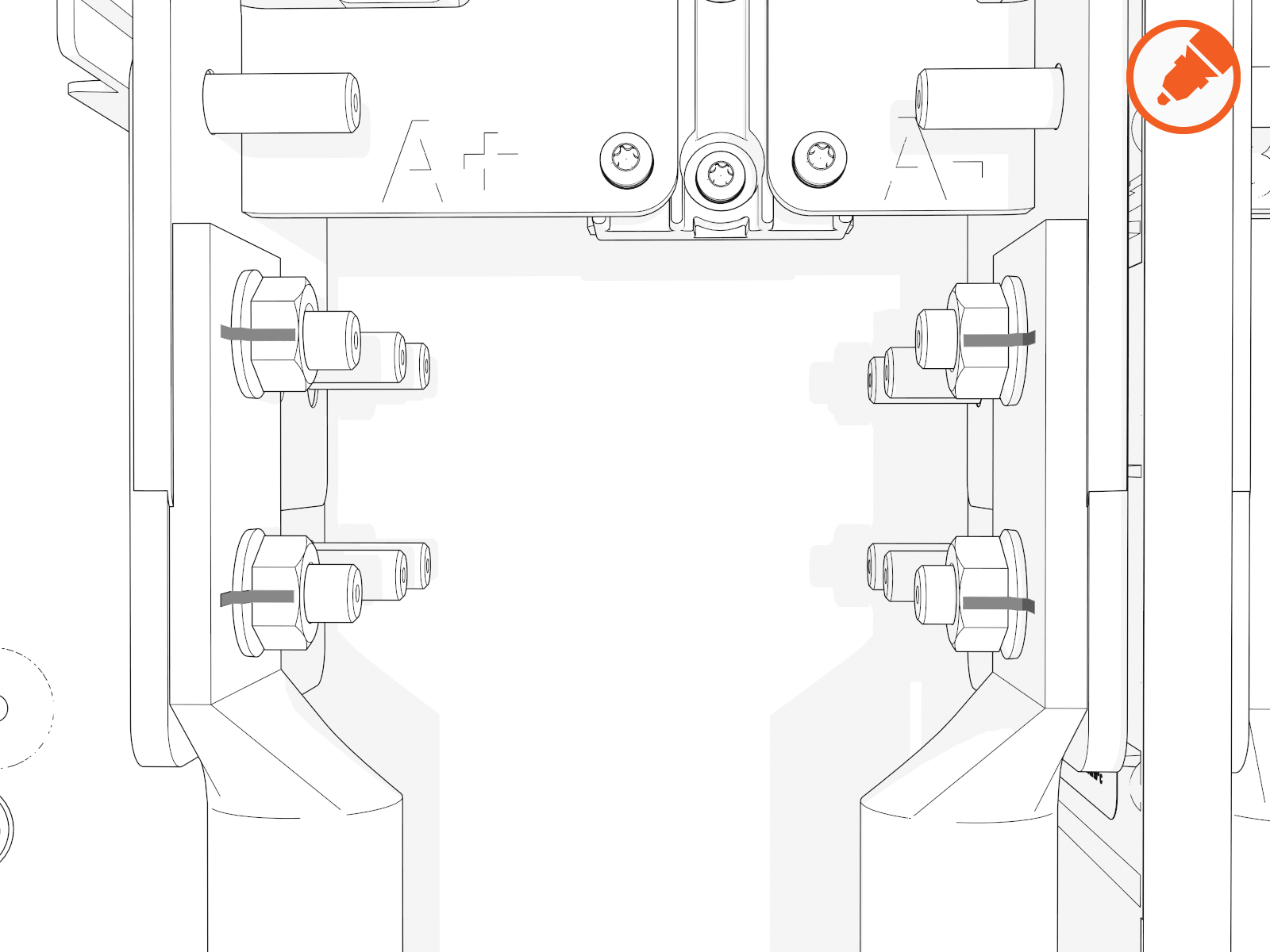
Land the DC lugs on the terminals. Torque nuts to 19 Nm (168 in-lb).
Fasteners are pretreated with dielectric grease.If using 500 kcmil conductors, you must use the back set of lugs to avoid interference with the surge suppressor panel.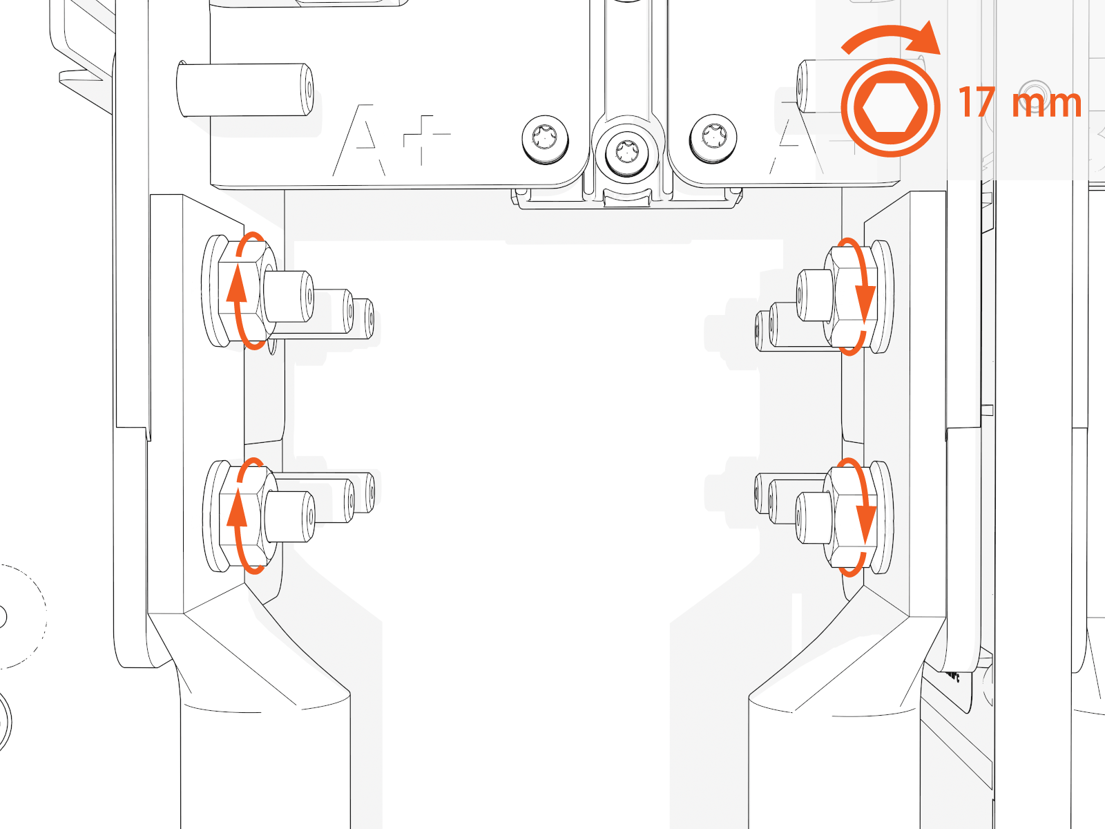
-
Mark all torqued power connections.
Install DC ground wire
-
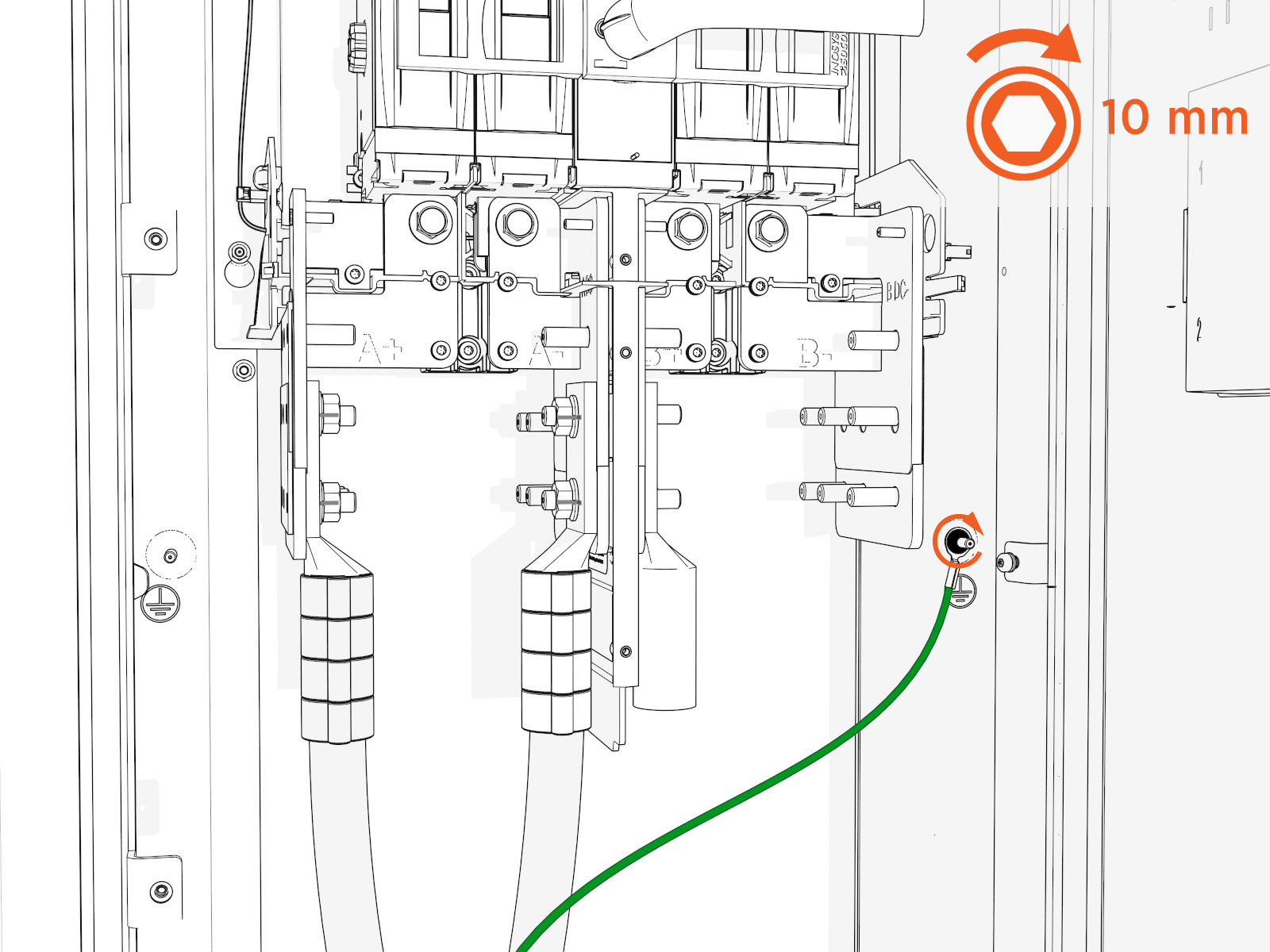
Land the ground wire onto a ground stud. Torque to 7 Nm (60 in-lb).
-
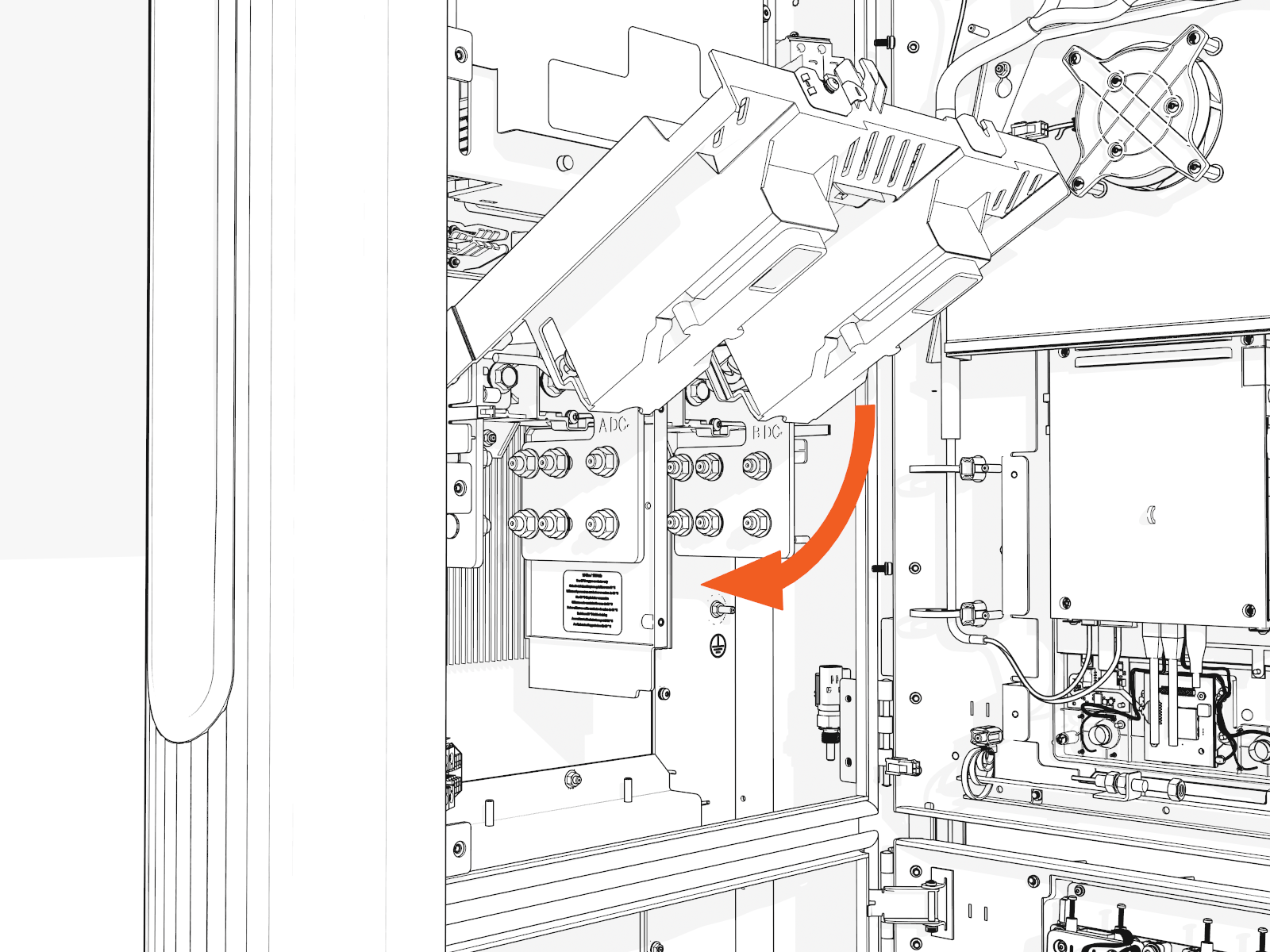
If you are installing the "Overhead" Mounted configuration:
Tilt down the upper safety cover to close.
-
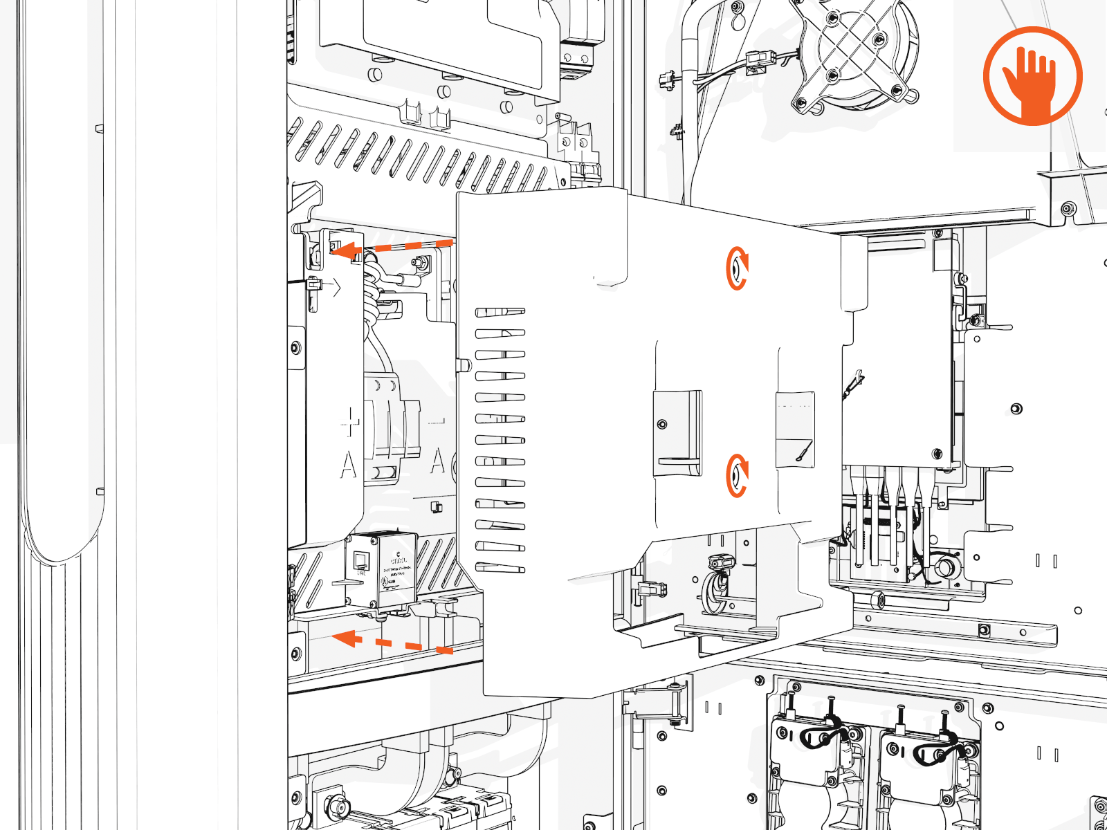
Position the power plate cover. Hand tighten the captive screws.
-
Reconnect Ethernet cable(s) to Ethernet surge suppressor into the same ports as before.
48 V DC Wiring
-
Check the 48 V DC wiring requirements in the site drawings:
48 V DC Wiring 48 V DC Wire Size
Conduit Size
Installation
16 mm2 (6 AWG
 American Wire Gauge)
21 mm (3/4 in)
Install two 48 V DC wires and one Ethernet cable into one conduit.
Use only copper conductor wire rated for 90 °C (194 °F).
-
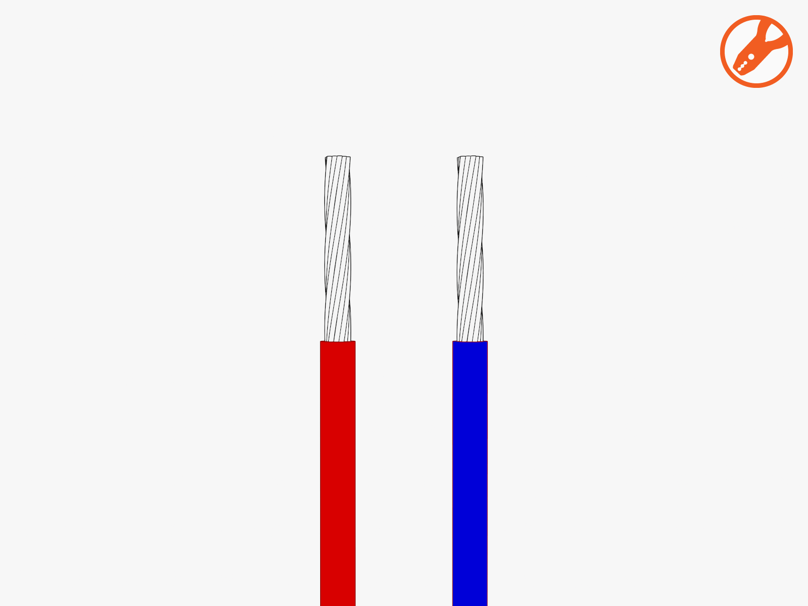
Strip the 48 V DC wires.
-
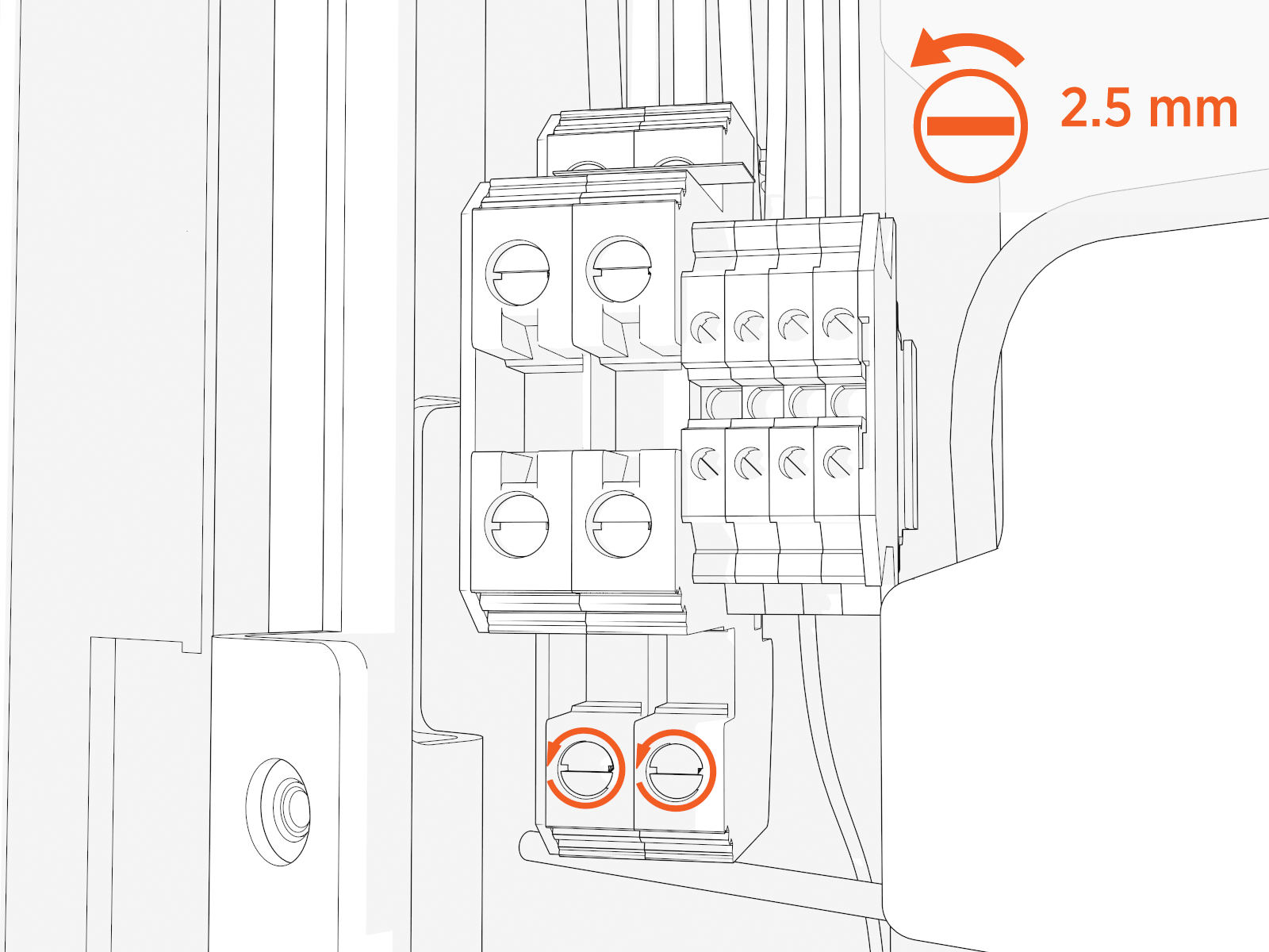
Loosen each terminal tab (upper cabinet, left side).
-
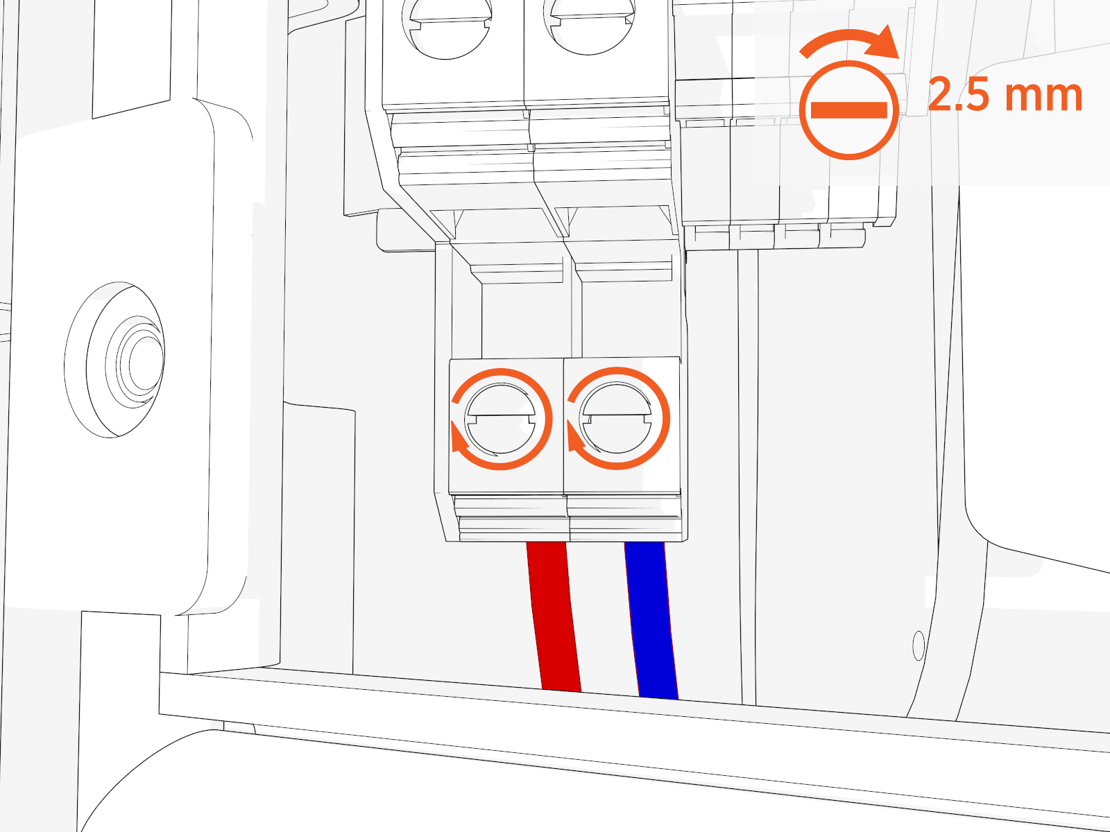
Seat the 48 V DC wires. Push-pull to test.
Cat6 STP Ethernet Cable
-
Trim the Cat6 STP
Shielded Twisted Pair Ethernet wires to length and allow for a service loop. Terminate both ends. -
Field crimp a shielded connector onto each Cat6 STP
Shielded Twisted Pair Ethernet wire. Use a straight-through T568B pattern.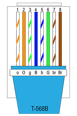
Do not connect the shield wire here at the Power Link 1000 termination.
-
Test each Ethernet wire for functionality.
-
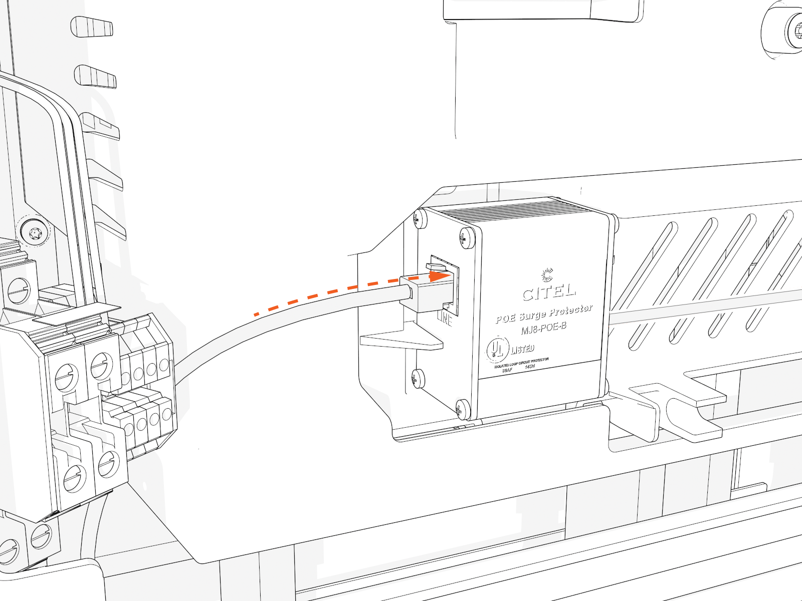
Identify which blue surge suppressors already have cables in the line-out (right) positions. Connect the Ethernet connectors to those surge suppressors at the line-in (left) positions. Push-pull to test.
Install Ethernet to USB Kit
If the site plan indicates the Power Link 2000 must be configured with a hardwire Ethernet connection to a network server, follow procedures in this section to install the Ethernet to USB Universal Serial Bus Kit and the hardwire connection.
Mount Ethernet to USB Module
-
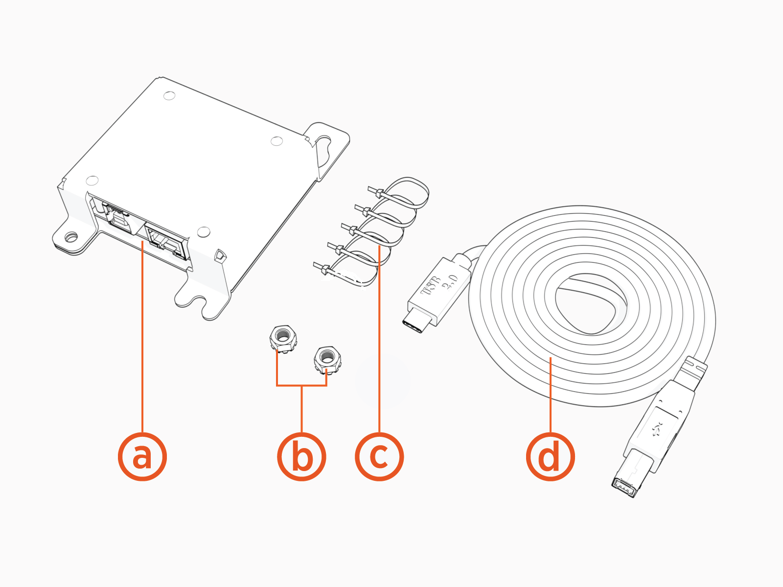
Unpack the Ethernet to USB
Universal Serial Bus Kit. Confirm all parts listed below are present.For any missing component, contact chargepoint.com/support.
-
Ethernet to USB
Universal Serial Bus module -
M5 star washer nuts (x2)
-
Zip ties (x5)
-
USB
Universal Serial Bus 3.0 Type B to Type C cable
-
-
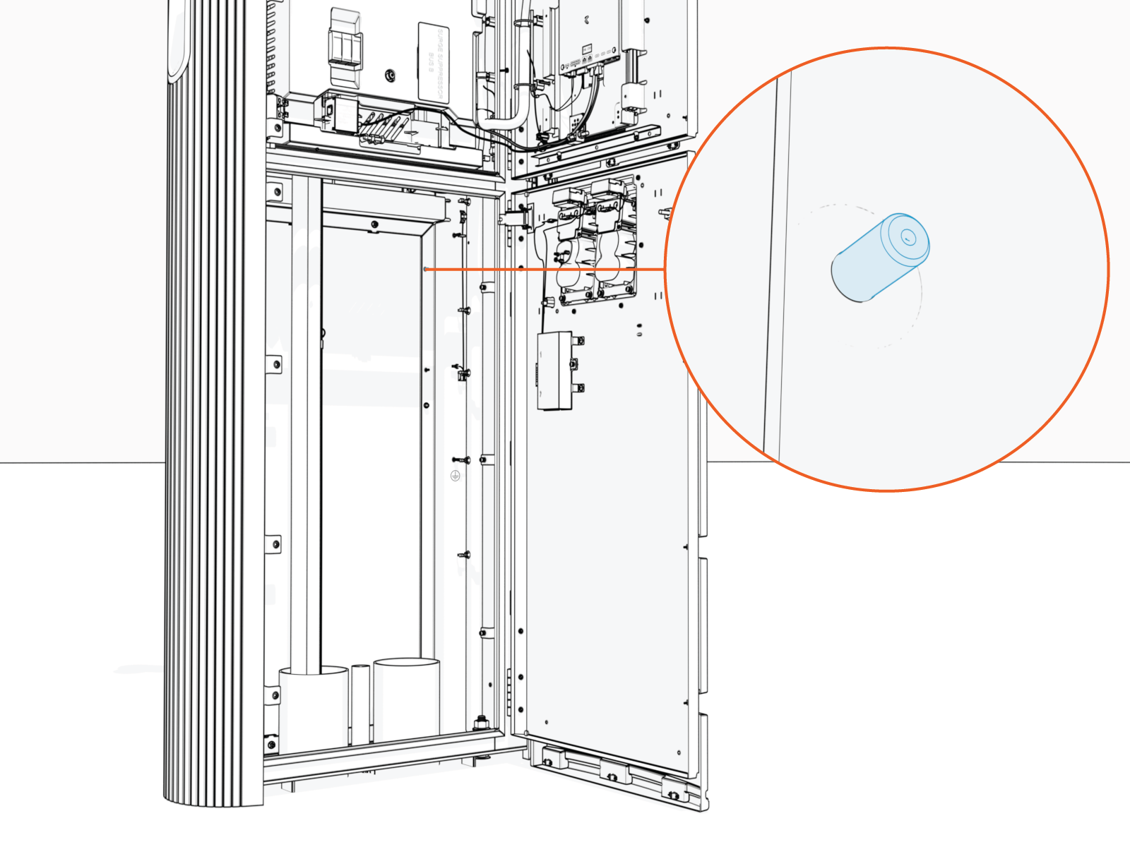
Locate a grounding stud on the product frame.
-
Install one of the provided M5 star washer nuts partially onto the stud. Thread the nut only halfway onto the stud.
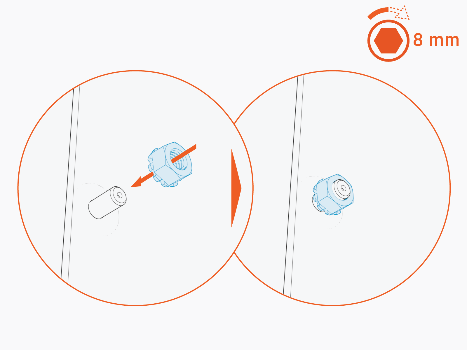
-
Mount the Ethernet to USB
Universal Serial Bus module onto the stud. Slide the module down to secure the keyhole tab to the stud.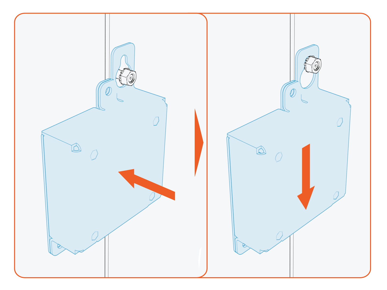
-
Torque the nut to 4.5 Nm (40 in-lb).
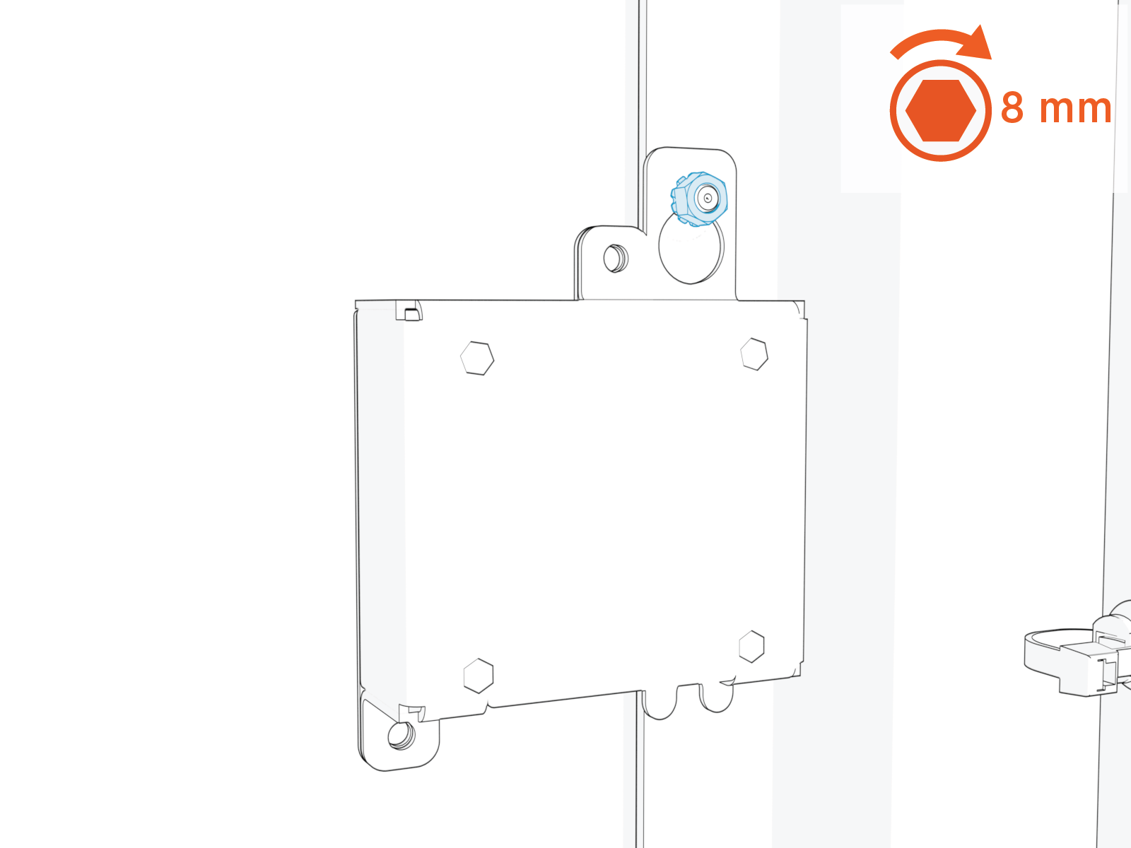
-
Plug the USB
Universal Serial Bus-B end of the USB Universal Serial Bus cable into the module.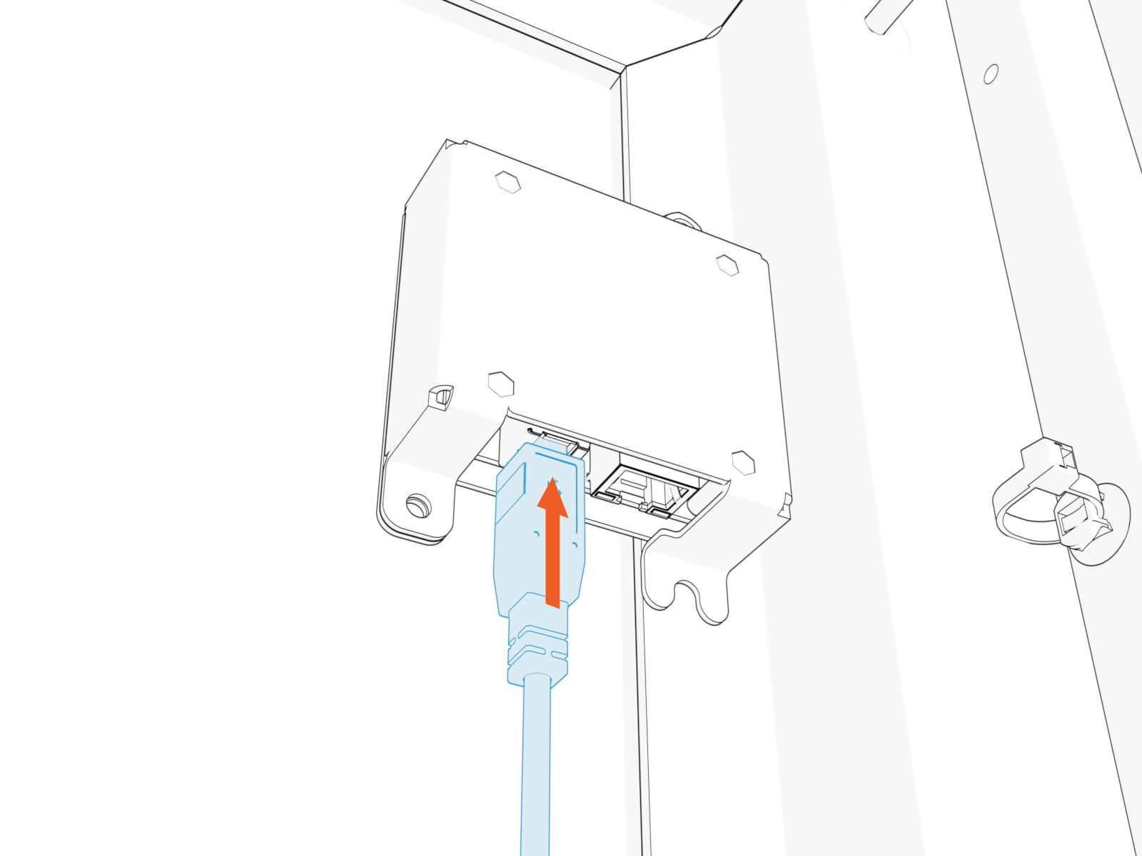
-
Route the cable through the door cable guide and along the main cable harness to the Control and Communication Module (CCOM
Control and Communications Module) located on the upper front door.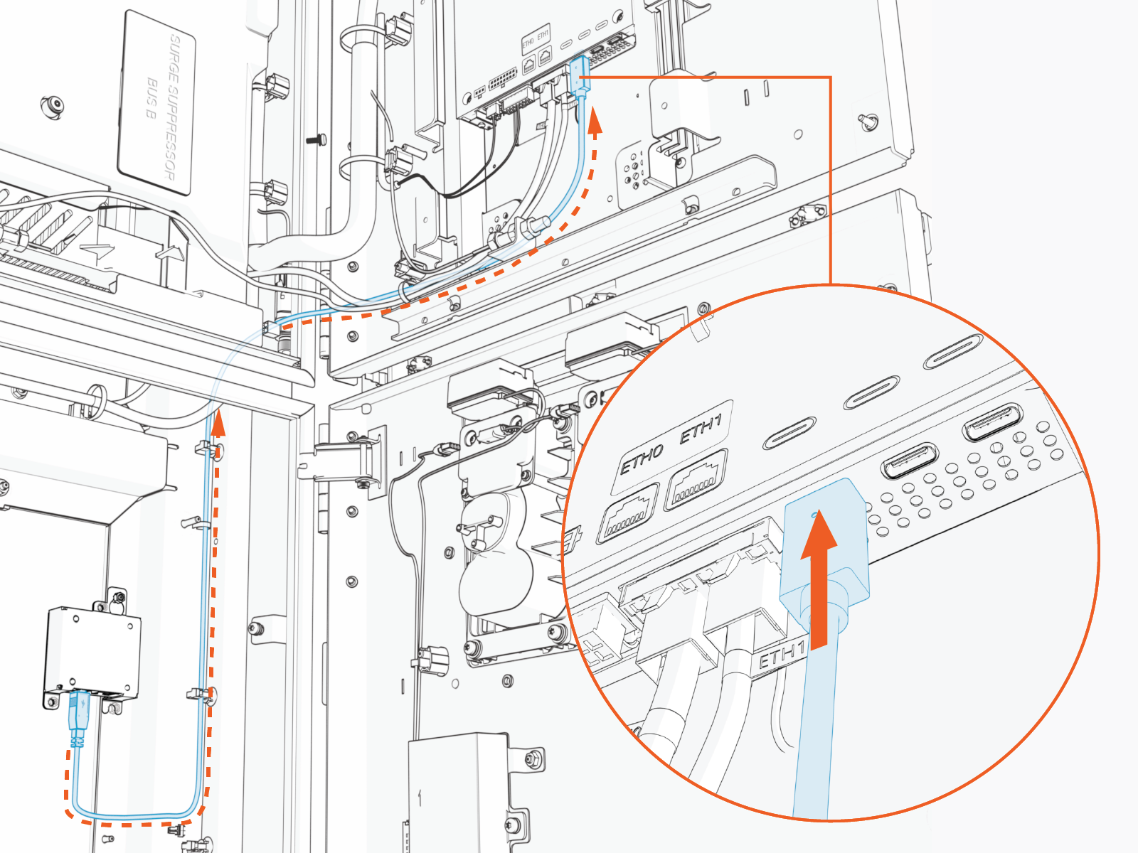
-
Connect the cable to the CCOM
Control and Communications Module. 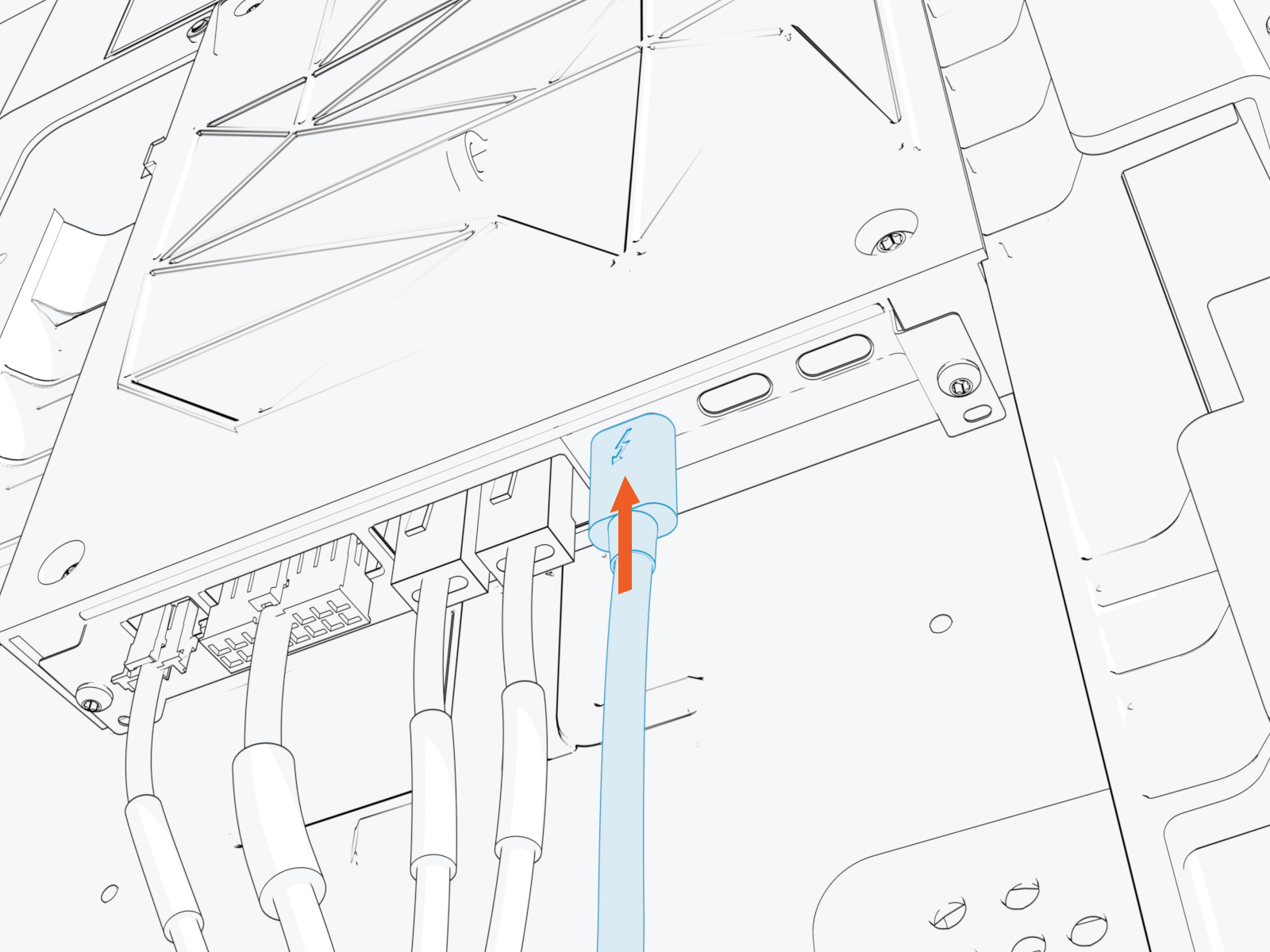
-
Secure the USB
Universal Serial Bus cable to the existing cable tie guides.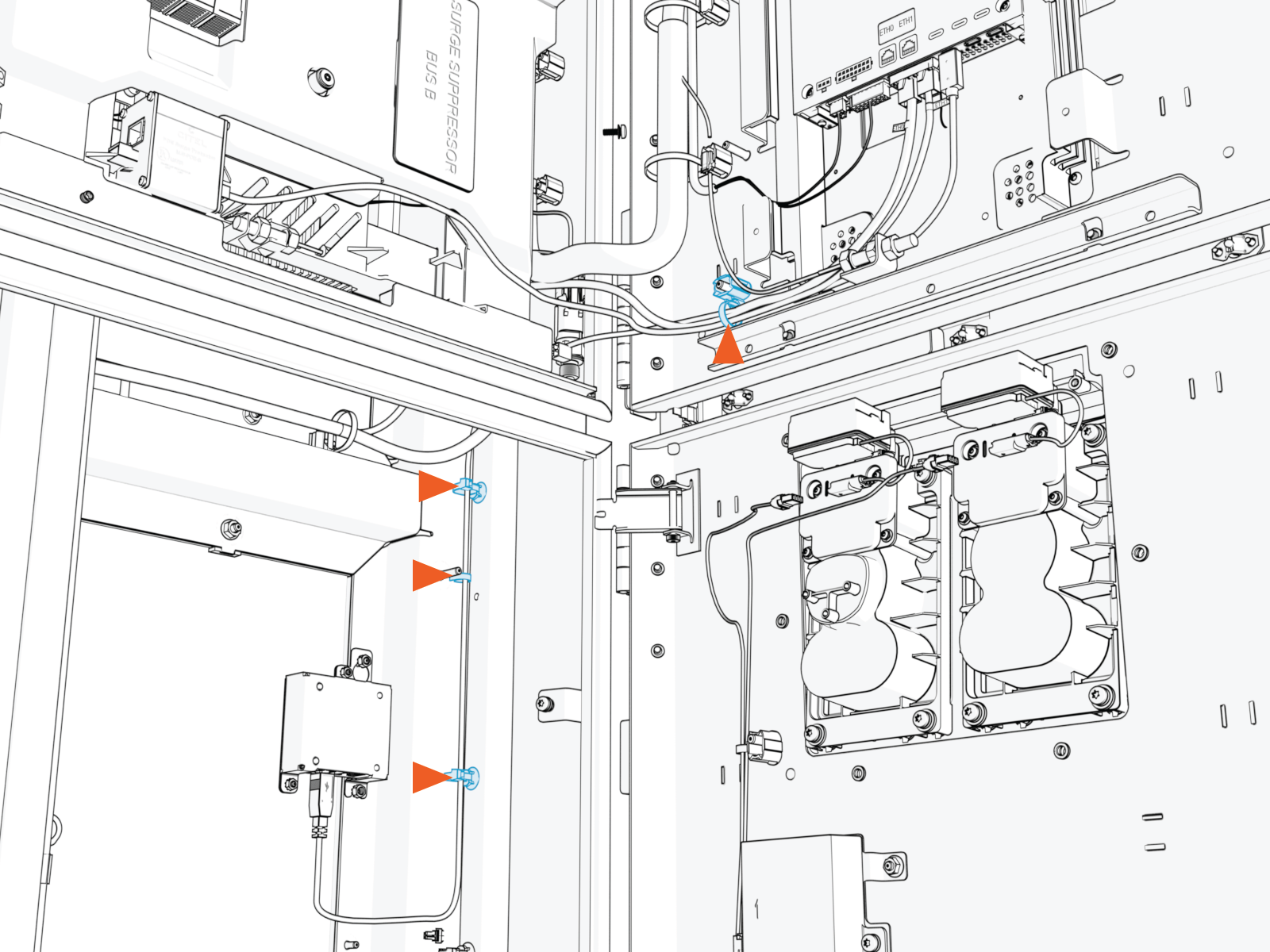
-
If needed, use the provided zip ties to secure the USB
Universal Serial Bus cable to the main cable harness.CAUTION:
-
Ensure the door can open and close without pinching or pulling of any cables.
-
Ensure the USB
Universal Serial Bus cable does not touch the HV DC High Voltage Direct Current wires when the door is closed.
-
Install Ethernet Cable
-
Pull the hardwire Ethernet cable into the enclosure and route it through existing cable guides to reach the Ethernet to USB
Universal Serial Bus module. Cut to length, allowing for a service loop.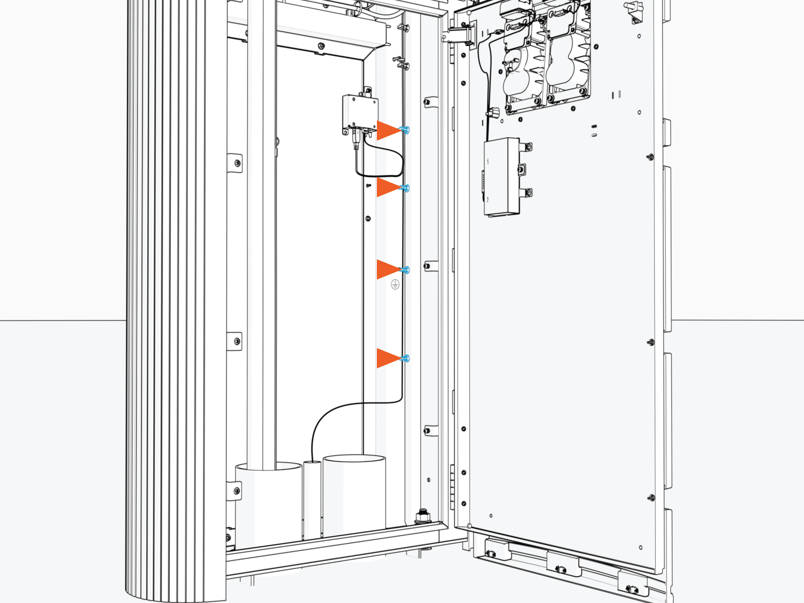
-
Field crimp an RJ45 connector onto the Ethernet cable. Use straight-through T568B pattern.
IMPORTANT: Do not ground the shield at this end of the Ethernet cable. Ground the shield at the end of the Ethernet cable that connects to the network server.

-
Test the Ethernet cable for functionality.
If using a Paige OSP Shielded GameChanger cable for a wire run length greater than 100 m (328 ft), follow the test procedure specified by Paige. See Paige GameChanger Resources.

-
Connect the Ethernet cable to the Ethernet to USB
Universal Serial Bus module.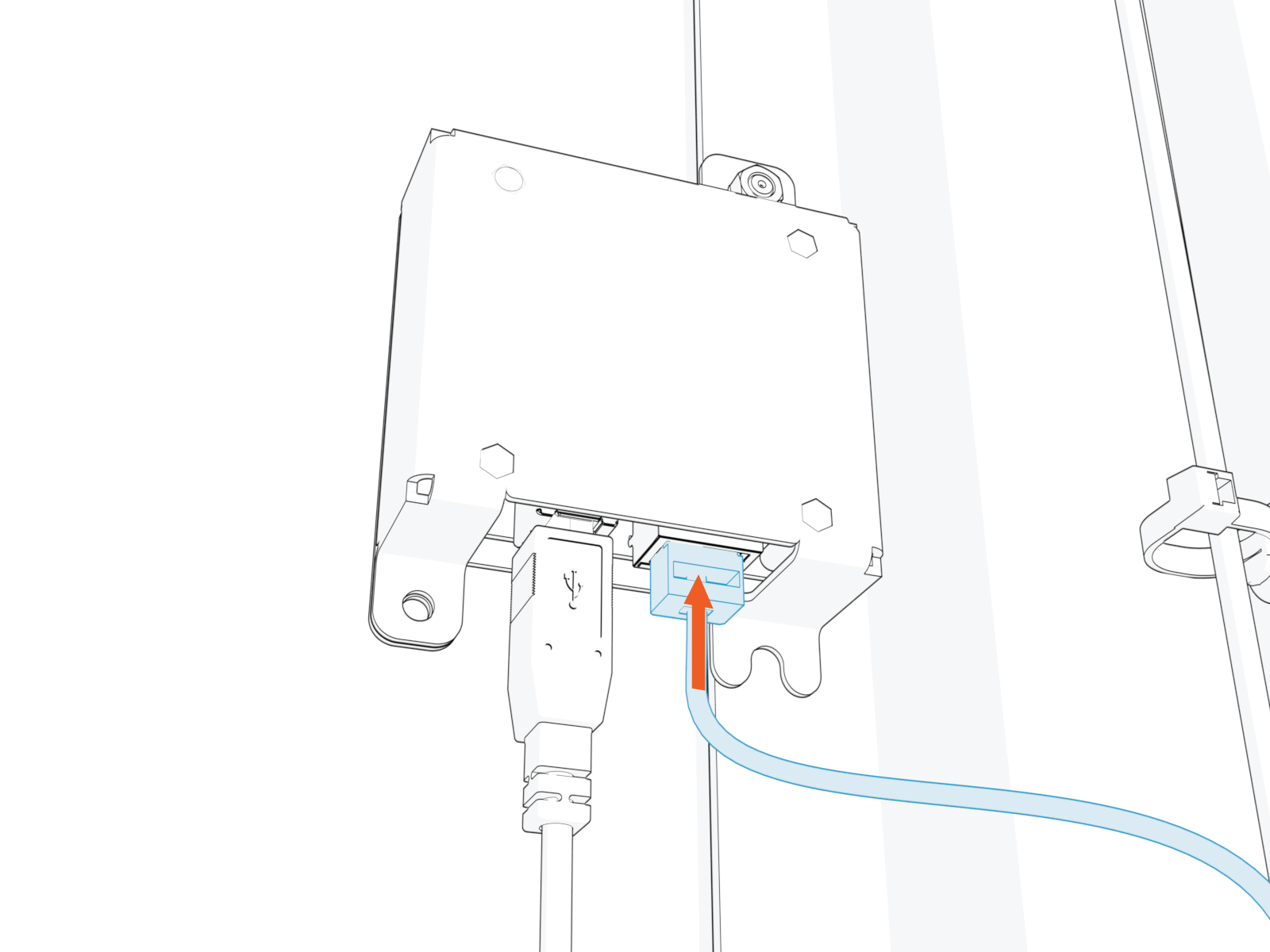
-
Route and plug the other end of the Ethernet cable into the network server.
Secure and Seal Gland Plate
-
Vacuum all wire ends and metal shavings.
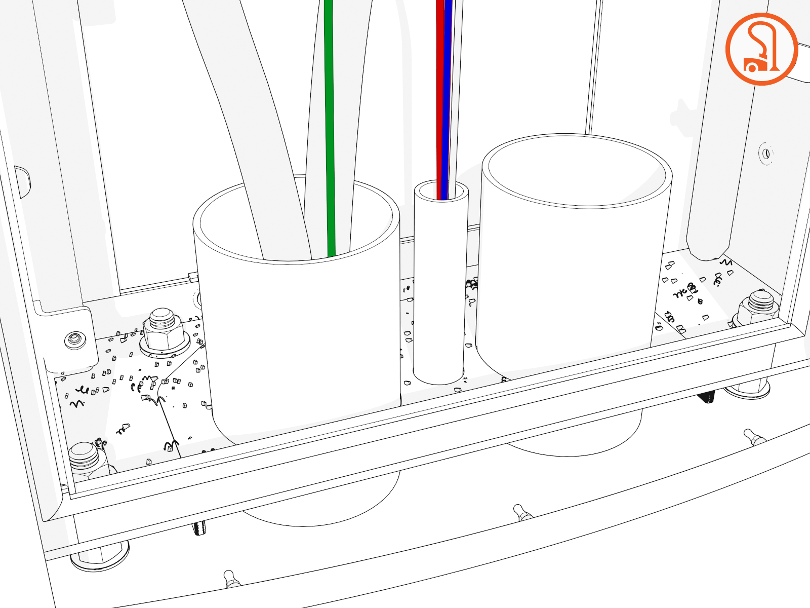
-
Secure wiring with clips as needed.
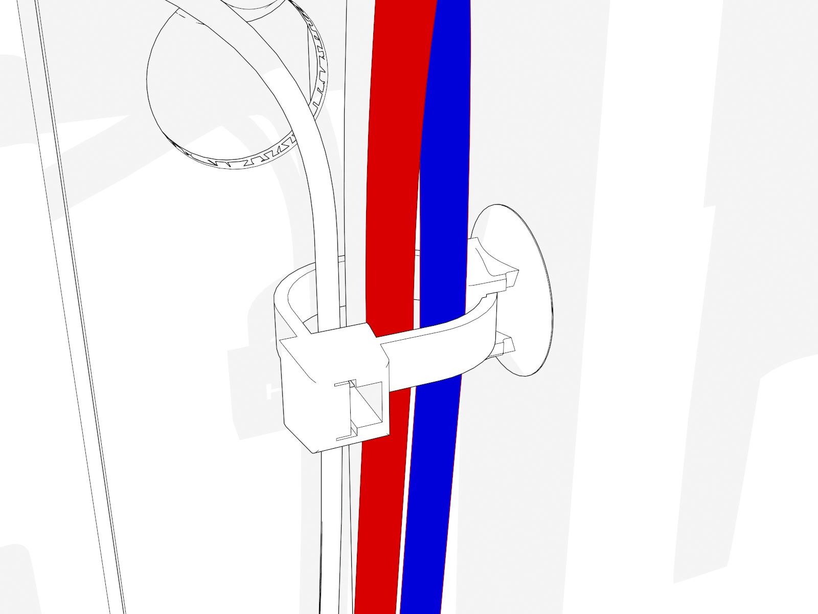
-
Align the gland plate and install screws.
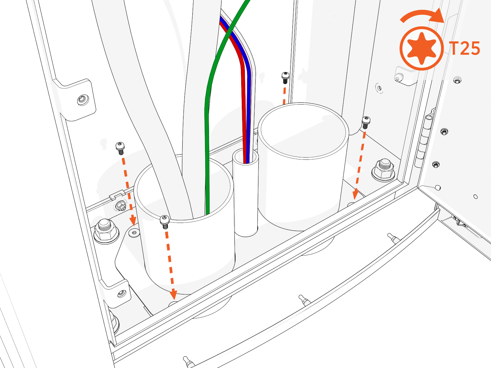
-
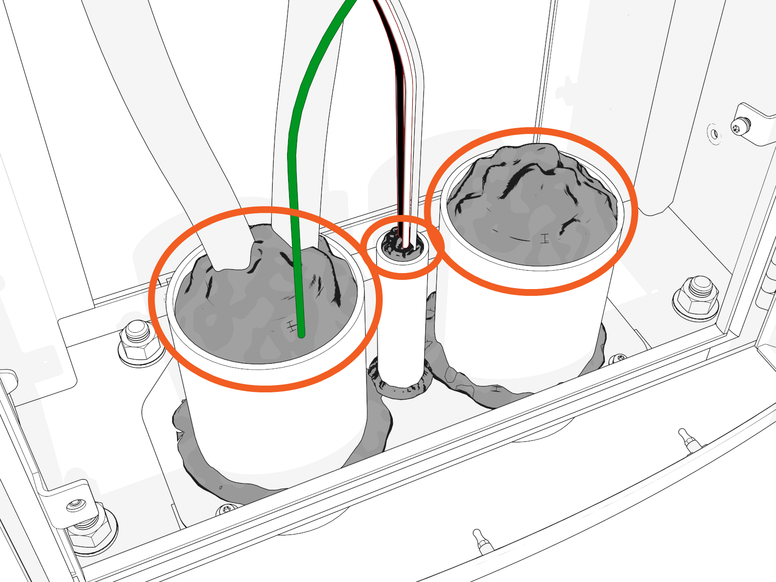
Use duct seal compound to seal inside conduit openings.
-
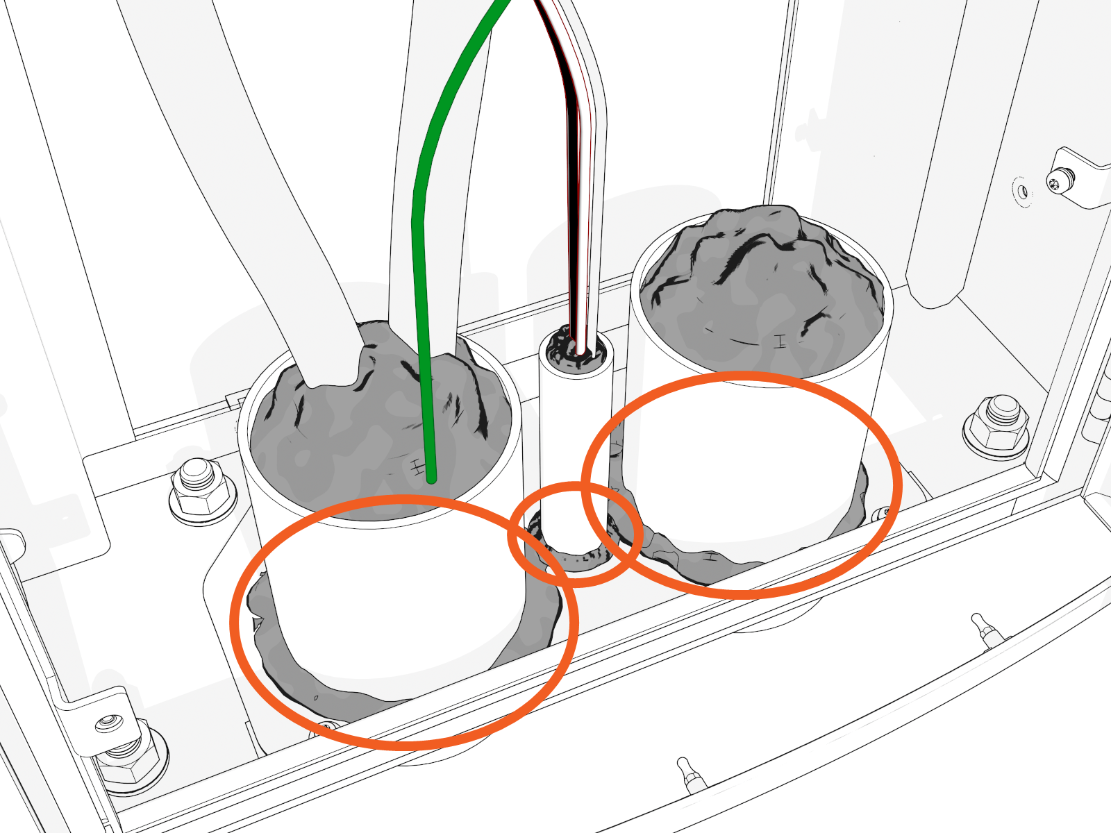
Seal the gland plate around and to each conduit.
Reinstall Lower Safety Panel (if applicable)
-
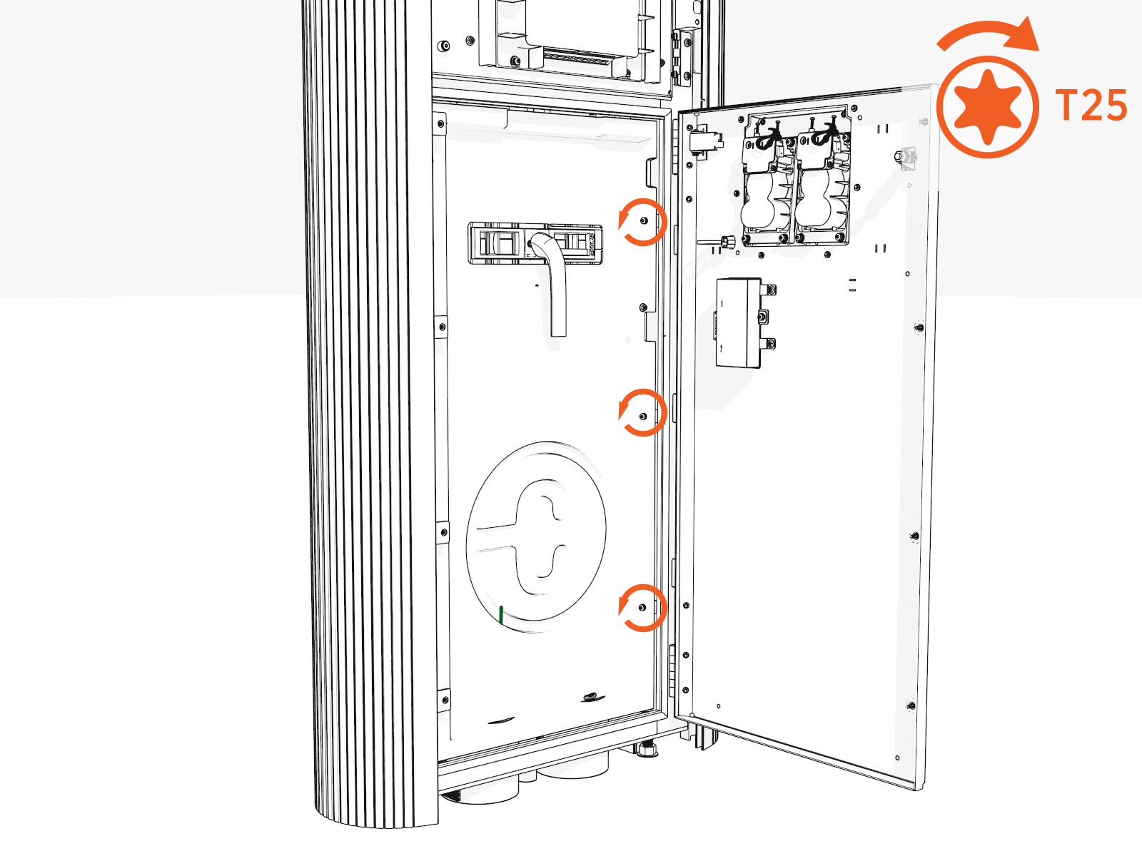
Slide in the panel behind the slots on the left.
-
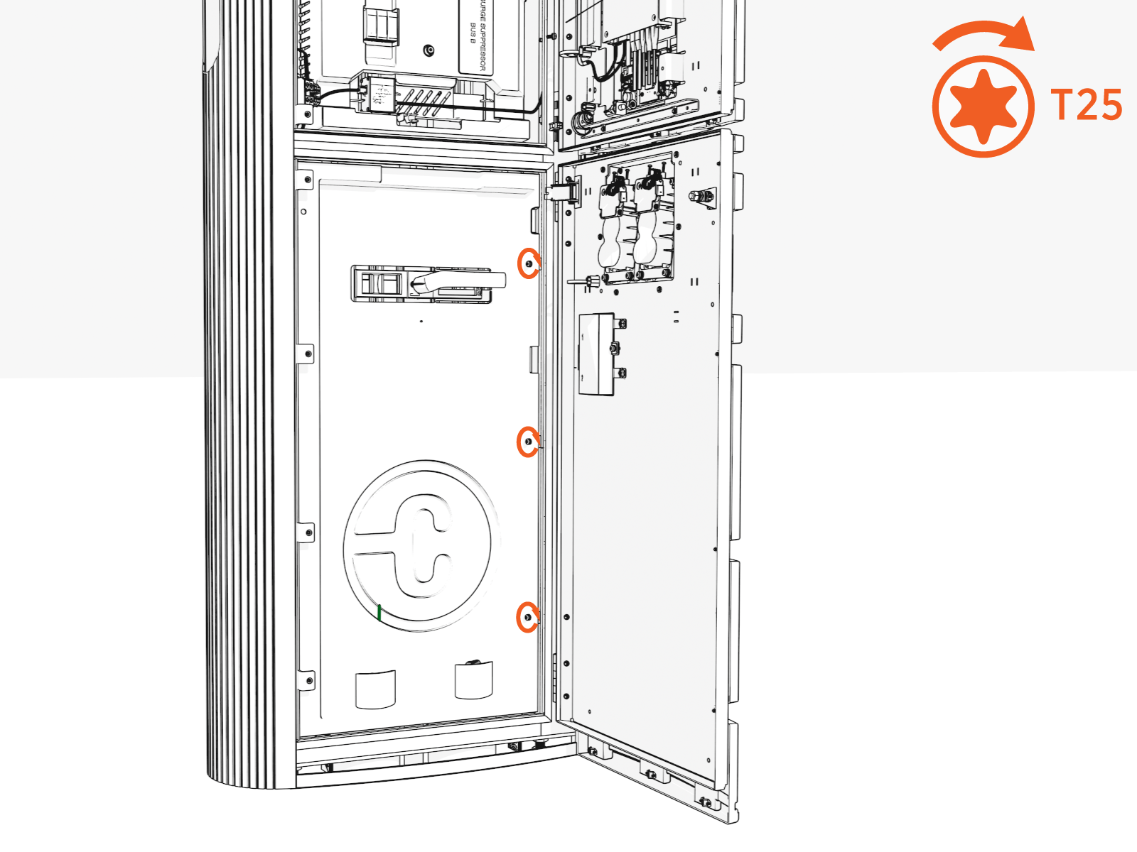
Install screws (x3) (use T25 security screwdriver) on the right side. Torque to 2.8 Nm (25 in-lb).