Site Planning and Placement
This section outlines general planning and placement requirements for Power Link 2000 sites.
Initial Site Guidelines
An onsite evaluation is needed to determine the wiring and conduit requirements from the electrical panel to the proposed parking spaces, as well as to measure cellular signal levels and identify suitable locations for any necessary cellular signal booster equipment.
If you have pre-existing infrastructure or are using your own preferred electrical contractor to prepare your site, a Power Link 2000 Construction Signoff Form completed by a ChargePoint Operations and Maintenance (O&M) partner is required to certify compliance with electrical code and to ensure everything was prepared to ChargePoint specifications.
Plan for Future Charging Capacity
Designing electrical infrastructure to support current and future needs for EV Electric Vehicle charging helps avoid costly upgrades later as demand for EV Electric Vehicle charging grows.
Consider these methods to prepare a site for future charging stations in a later phase of work:
-
Add extra capacity if electrical panels are being upgraded now.
-
Use sub-panels as a way to shorten electrical paths.
-
Maximize the conduit and conductor sizes (to product specifications) between the main electrical panel and future stations to prevent needing to re-pull wires or trenching work if the site uses underground wiring.
-
Underground service wiring conduits can be pre-staged if the correct site construction is performed in advance. Allowed terminations include a distribution unit, junction box, or plugged conduit. This eases cable pulls for future stations.
System Placement
The placement of Power Link 2000 must meet the following requirements:
-
Do not install Power Link 2000 in a Class 1 hazardous location, as classified by NEC
National Electric Code or local codes. -
Site conditions must be compatible with the following specifications listed in the Express Power Link 2000 Datasheet:
-
Operational altitude
-
Operating temperature
-
Operating humidity
-
Enclosure rating
-
To minimize costs, choose station locations that are close to the available electrical infrastructure. Selecting nearby locations help minimize long wire runs as well as any conduit or trenching work if the site uses underground wiring.
Power Link 2000 must be installed on a structure that is rated to support its weight. A level concrete base is recommended for pedestal-mount Power Link 2000 and a flat wall or gantry is recommended for overhead-mount Power Link 2000. Asphalt cannot support the full weight of Power Link 2000. Failure to install the Power Link 2000 on a suitable structure may cause it to tip over, resulting in death, personal injury, or property damage.
Layout considerations:
-
Determine appropriate ground anchoring locations where concrete exists or can be installed (no asphalt surfaces).
-
Consider locations where it will be easy to add future stations.
-
If using conduits to pull wires, determine the best conduit layout to minimize linear conduit costs to multiple parking spaces. If possible, avoid or minimize trenching requirements, especially more costly trenching to run conduit under asphalt surfaces.
-
Determine if the existing utility service and electrical panel capacity is sufficient. Identify costs for any necessary upgrades and/or a new dedicated electrical panel. ChargePoint recommends using a licensed electrician to evaluate available capacity and identify any upgrades that may be required.
-
If a dedicated EV
Electric Vehicle electrical panel is required, choose a panel located close to the existing electrical supply. -
Measure cellular signal levels to ensure adequate cellular coverage at the station locations. To ensure adequate signal strength in underground or enclosed parking structures, cellular repeaters may be required. For more information, see Connectivity.
-
ChargePoint recommends avoiding locations under trees where sap, pollen, or leaves would fall on the charging station and increase the station owner’s site maintenance workload.
Guidelines for Different Parking Arrangements
-
Choose adjacent parking spaces in an area with adequate lighting.
-
Consider how easily drivers can find the stations they need to access.
-
Check local requirements for accessibility and pathway width, sometimes called “path of travel”, to ensure that station placement does not restrict sidewalk use.
-
A pad built into the head of a parking space (instead of on the sidewalk) is allowed if local code allows it compared to the minimum parking space length, and the pad meets all pad requirements listed in this document.
Cable reach
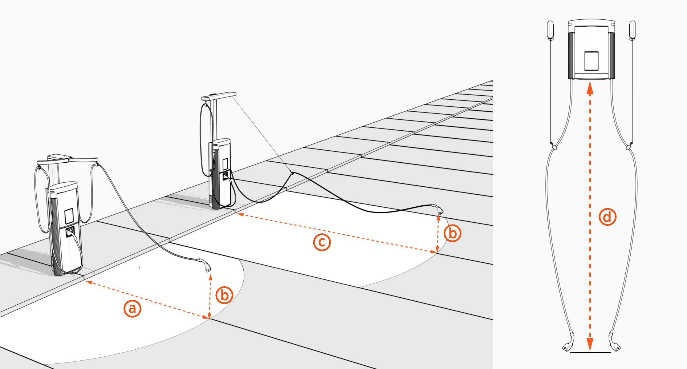
The following table provides the maximum cable reach from the station to charge port on a vehicle:
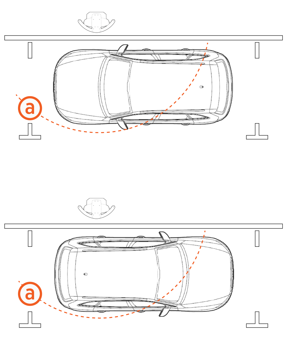
The cable reach specifications for both the tall CMK Cable Management Kit and overhead CMK Cable Management Kit include the full extension of a tether cord from the CMKs, as depicted in the illustration above.
|
|
Pedestal-mount Power Link 2000 |
Overhead-mount Power Link 2000 |
||
|
Standard CMK |
Overhead CMK |
|||
|
Cable length |
LCC Non-LCC |
7.6 m (25 ft) |
7.6 m (25 ft) |
|
|
Cable reach |
Horizontal or vertical reach |
3.76 m (12 ft 4 in) Horizontal (a) |
6.09 m (20 ft) Horizontal (c) |
4.57 m (15 ft) |
|
Height above ground |
0.6 m (2 ft) (b) |
Not applicable |
||
-
Diagonal stall parking is not recommended.
-
Place each Power Link 2000 to maximize cable reach for the varied charge port locations on different EVs.
Commercial or Public Station Placement, Single or Dual Cable
For stall parking, ChargePoint recommends using perpendicular parking stalls that allow a vehicle to enter either front-first or rear-first, to better accommodate the varied locations of EV Electric Vehicle charge ports.
While ChargePoint tests charging stations with a majority of upcoming vehicles, ChargePoint cannot guarantee the port locations of future vehicles and cannot warrant the configurations proposed will work for all vehicles.
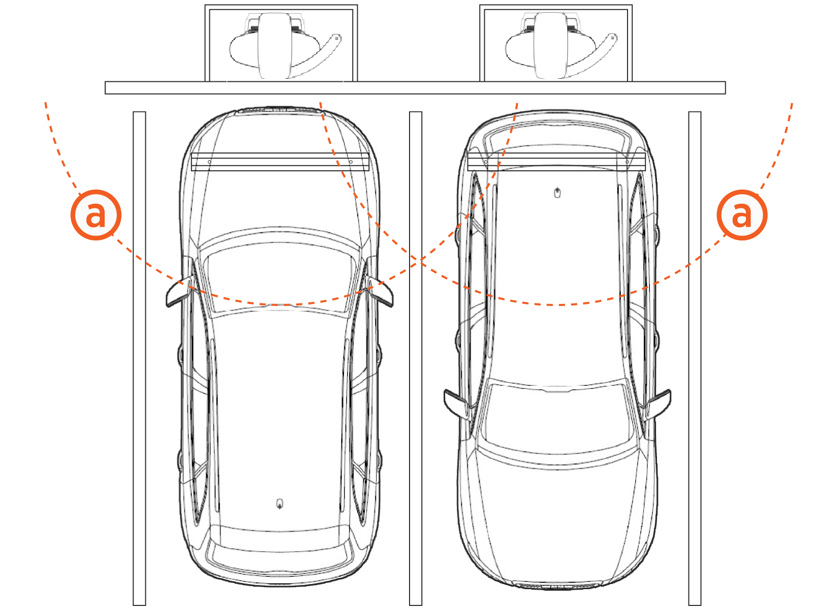
This illustration depicts a charging station with a dual cable.

-
Cable reach radius: 3.76 m (12 ft 4 in)
The following three illustrations depict charging stations with single cables.
-
Cable reach radius: 3.76 m (12 ft 4 in)
-
Cable reach radius: 3.76 m (12 ft 4 in)
Fleet Parking Arrangement
-
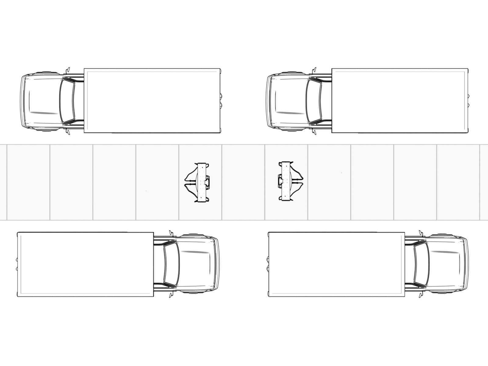
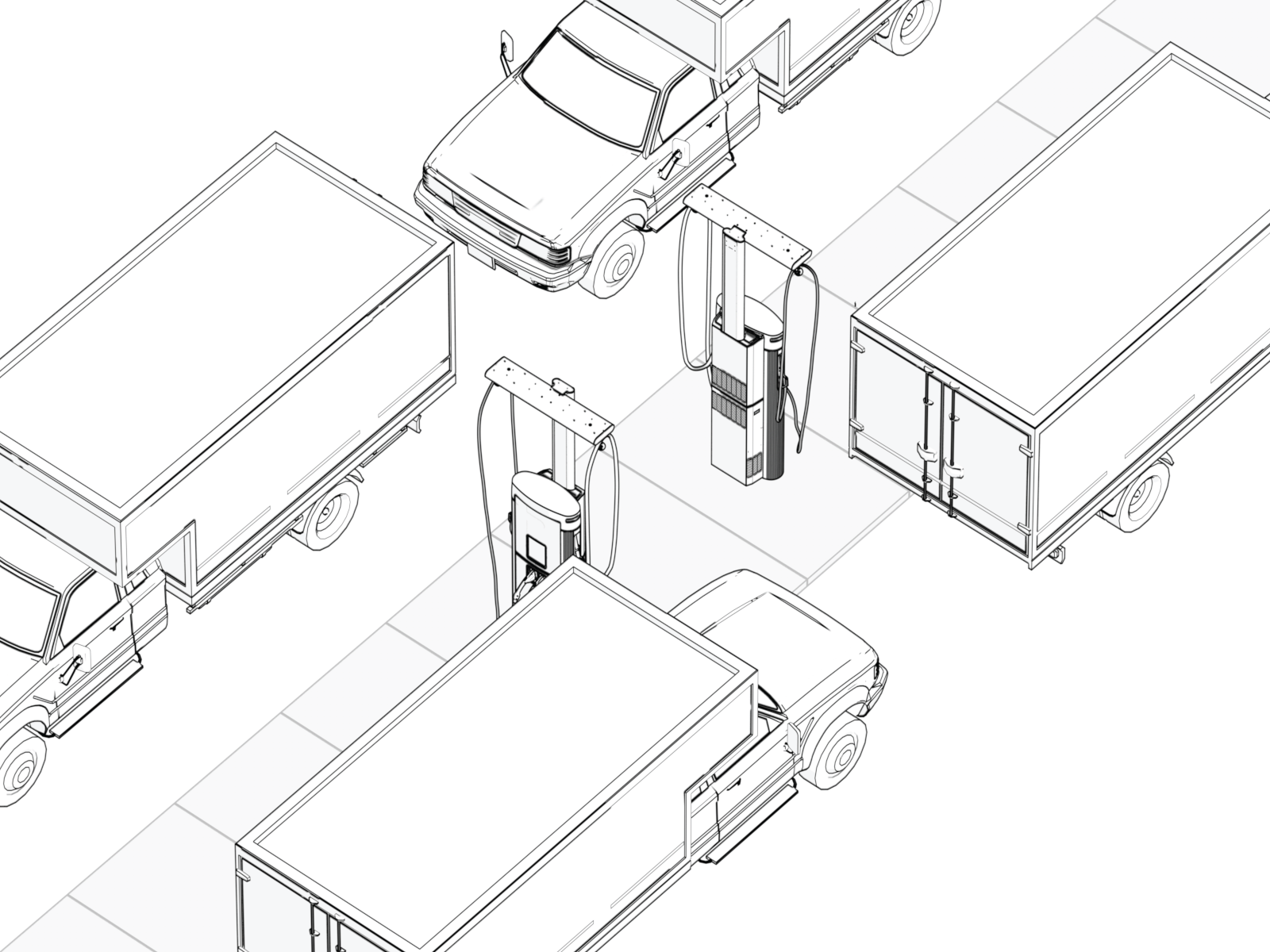
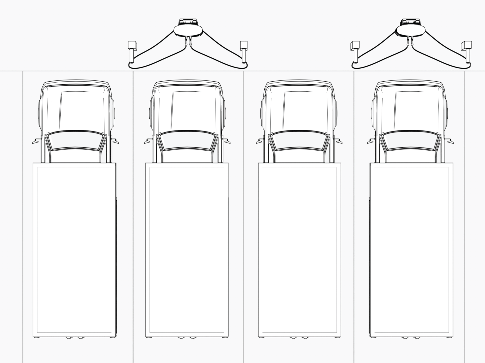
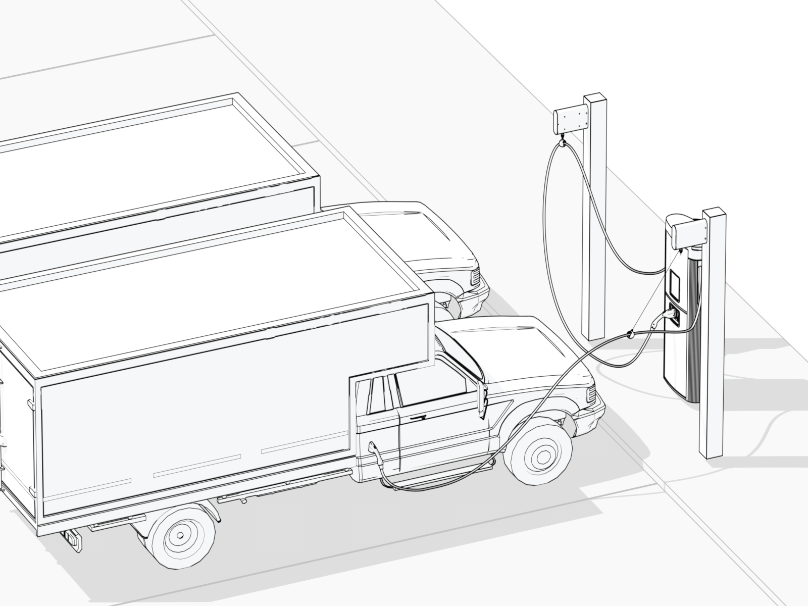
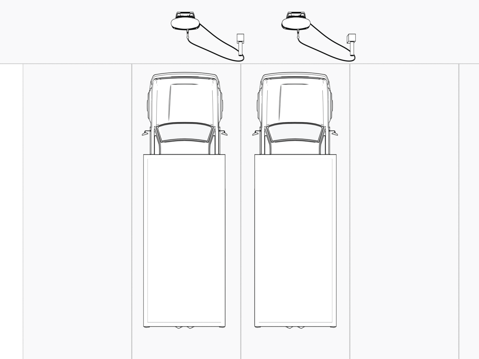
Stall parking (Dual Charge Cable): For installing dual charge cable Power Link 2000 stations, consider placing the station in front of every other parking space. Additionally, align the overhead CMK
Cable Management Kit tether with the parking stripes on either side of the charging station.
|
|
|
-
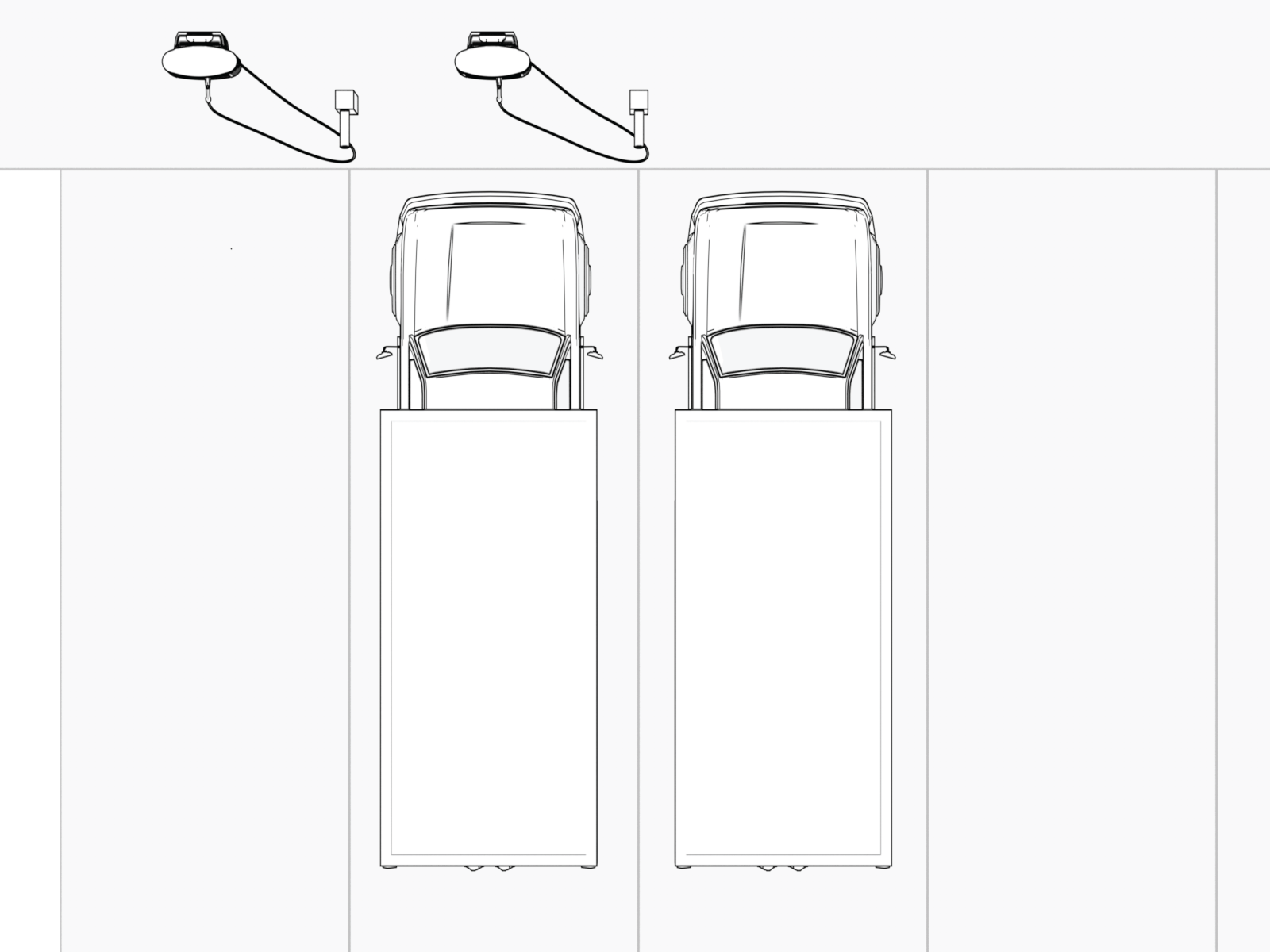
Stall parking (Single Charge Cable): Power Link 2000s with single charging cables are always configured with the charging cable on the right side of the enclosure. Align the overhead CMK
Cable Management Kit tether with the parking stall stripe adjacent to the vehicle's charging port. The illustrations below depict parking of the vehicles in relation to the charging stations, based on the side where the vehicle's charging port is located.
| Vehicles with left-side charging ports | Vehicles with right-side charging ports | |
|---|---|---|
|
|
|
|
-
Island parking: ChargePoint recommends placing a station in the center of the island facing away (station front is perpendicular to vehicles) in the same orientation. This allows the station to be accessible from both sides of the island.
|
|
|