Construction Signoff Form

This form ensures the site for your ChargePoint solution has been prepared as specified, by you or by your chosen contractor, before beginning installation. Submit this completed form and the required photos to installdispatch@chargepoint.com. Detailed datasheets, site design guides, and installation guides defining ChargePoint specifications are available at ChargePoint Product Reference Documents.

IMPORTANT: All installations must comply with local and regional code. ChargePoint provides concrete pad guidance applicable for most sites in the site design; however, pad sizes for a given site might be smaller or larger due to site conditions. Ensure site drawings have been completed and approved by a structural engineer for the site.

If the installer arrives to the installation site and finds any signoff items incomplete, you will incur a separate re-dispatch fee.

Site & Contractor Information

Site Information

Contractor Information

Site address:

Company name:


Site lead name:


Number of stations to be installed:

Site lead job title:


Contact name:

Site lead email:


Contact phone:

Site lead phone:


Contact email:

Date work began:


Required Pictures

Provide the following photographs for each location during the construction process:

Required Pictures


1. All trenching completed and conduit/ducting is in place.


2. Completed mount locations with anchor bolts (x4 per Power Hub cabinet) and conduit stub-ups (if used) in place.


3. Overall space around each mounting location, showing all service clearances are available.

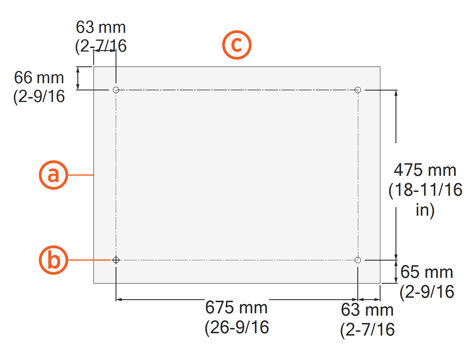
Civil Work, Power Hub


1. The concrete pad was designed, installed and approved as follows:
  1. If pad was newly poured:

    • The pad was designed and installed based on one of the conservative stability specifications listed in the Express Plus Power Hub Site Design Guide, in accordance with site-specific wind, seismic and soil conditions.

      -or-

    • The pad was designed by a structural engineer based on site-specific conditions and based on the structural parameters listed in the Express Plus Power Hub Site Design Guide.

  2. If using existing concrete surface:

    • The pad was inspected and approved by a structural engineer based on the structural parameters listed in the Express Plus Power Hub Site Design Guide.


2. The mounting surface is smooth and does not exceed a slope of 20 mm per meter (0.25 inches per foot).
 
3. Walls, fences, or slopes do not prevent water from draining from the pad.


4. The anchor bolts are positioned correctly in the concrete pad:
  1. Power Hub cabinet footprint (top down view)

  2. 5/8 in anchor bolts (x4), HILTI HAS-R 316 SS, with 102 mm (4 in) embedment in concrete pad, and 38 mm (1.5 in) length exposed above concrete, plumb to concrete surface

  3. Cabinet rear side


5. The conduit stub-ups (if used) are positioned correctly:
  1. Power Hub cabinet footprint (top down view)

  2. Allowed area for conduit and wire entry

  3. Conduit stub-ups

    Conduit stub-ups shown in diagram are for illustrative purposes only. Stub-up placement must match specifications called out by the site design plan.

  4. Cabinet rear side

6. The open space and service clearance requirements are met:

  1. Front: 792 mm (31-1/4 in)*

  2. Right side: 51 mm (2 in)**

  3. Left side: 51 mm (2 in)**

  4. Rear: 51 mm (2 in)*

*Front and rear clearances must be at grade level +/- 13 mm (1/2 in)

**Side clearances can be shared between Power Blocks and Power Hubs as long as:

  • Front and rear clearances are maintained

  • At least 457 mm (18 in) of clearance exists at each end of a row of Power Blocks and Power Hubs, as shown below in a top down view

  • Access to the back of each Power Block exists for maintenance

  • If Surface Conduit Entry is used, side clearances must also allow for surface cable bend and pull.


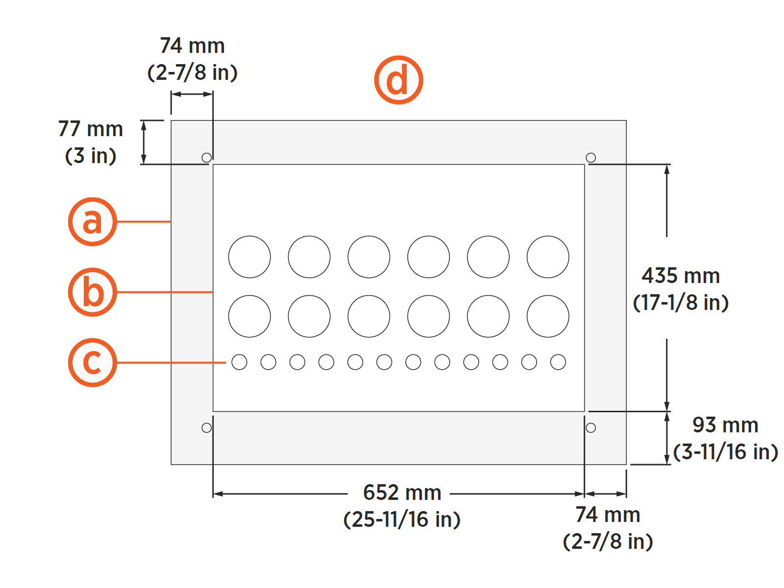
Electrical Work, Power Hub


1. All electrical infrastructure has been completed per local codes. LV DCClosed Low Voltage Direct Current and HV DCClosed High Voltage Direct Current wires are copper, and are properly sized and rated per the Express Plus Power Hub Site Design Guide.


Europe

Conductor

Conductor Rating

# of Poles

Insulation Type

Temp Rating

HV DCClosed High Voltage Direct Current input

350 A, 1000 V

2 + PE

XLPE

90°C (194°F)

HV DCClosed High Voltage Direct Current output

350 A, 1000 V

2 + PE

XLPE

90°C (194°F)

48 V DC input

28 A,

48 V Circuit Voltage,

1000 V insulation rating

2

XLPE

75°C (167°F) required,

90°C (194°F) recommended

48 V DC output

26 A,

48 V Circuit Voltage,

1000 V insulation rating

2

XLPE

75°C (167°F) required,

90°C (194°F) recommended

North America

Conductor

Conductor Rating

# of Poles

Insulation Type

Temp Rating

HV DCClosed High Voltage Direct Current input

350 A, 1000 V

2 + ground

XHHW

90°C (194°F)

HV DCClosed High Voltage Direct Current output

350 A, 1000 V

2 + ground

XHHW

90°C (194°F)

48 V DC input

28 A,

48 V Circuit Voltage,

1000 V insulation rating

2

XHHW

75°C (167°F) required,

90°C (194°F) recommended

48 V DC output

26 A,

48 V Circuit Voltage,

1000 V insulation rating

2

XHHW

75°C (167°F) required,

90°C (194°F) recommended

Record conductor size, voltage rating, and insulation type:

Conductor

Size, voltage rating, and insulation type

HV DCClosed High Voltage Direct Current


DC Ground


48 V DC


2. If cables are pulled, attach copies of AC, 48 V DC and HV DCClosed High Voltage Direct Current conductor insulation test reports.
 
3. Outdoor rated Ethernet Cat6 STPClosed Shielded Twisted Pair cables are present, without terminations. Cable lengths must accommodate 3 m (10 ft) of service loop at each end.
Site Comments or Other Details

Site Comments


I, _______________________________________________ hereby certify that the scope of work in this form has been correctly completed.

Signature Block

Signature

Date