Latch Replacement J1772
This section describes the procedure to replace the latch.
Before you Begin
Complete the following steps to remove the charging cable:
-
Turn off power to the charging station at the circuit breaker.
-
Unplug the power cord, if present.
RISK OF SHOCK. Before performing any procedure, you must disconnect the power to the charging station at the service panel. Follow local code to de-energize the applicable circuit and lock out/tag out the disconnect before proceeding. Use a multimeter to test that power is off. Keep power off for the circuit until all cover panels are correctly reinstalled and the work is complete. FAILURE TO FOLLOW THESE INSTRUCTIONS CAN RESULT IN SERIOUS INJURY, LOSS OF LIFE, AND/OR PROPERTY DAMAGE.Do not plug the new power cord in before completing the replacement procedure.

Required Tools and Materials
The replacement kit for J1772 connector latches includes:

-
Hex wrench
-
Repair tool
-
Drive bolt
-
Guide pin
-
Square nut (not shown)
-
Consumable latches and springs labeled for Type A and Type B connectors (not shown)
Assemble the Tool
To assemble the tool, perform the steps below:
-
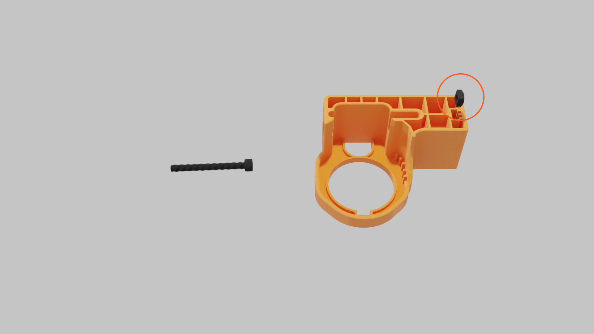
Place the square nut inside the tool body.
-
Insert the drive bolt from the side of the tool body and tighten.

-
Keep the guide pin and hex tool handy for future steps.
Identify Connector Type
Identify the connector type before you start repairing.
Type A
-
Three oval shaped cutouts on the side of the connector
-
Silver latch pin
-
Replacement latch narrows at the tip and uses a longer silver-colored spring

Type B
-
No cutouts on the side
-
Black latch pin
-
Replacement latch stays wide at the tip and uses a shorter dark-colored spring

Repair Procedure
Follow the steps below to repair the latch:
-
Use the hex wrench to loosen the drive bolt. Insert the guide pin into the pin slot.

-
Insert the J1772 connector into the repair tool, and push it into place until the latch pin aligns with the middle of the exit hole.

-
Use the hex wrench to tighten the drive bolt. The latch pin will slowly extend from the exit hole. If you feel too much resistance but don't see the pin move, check the alignment and try again.

-
Tighten the drive bolt until the latch pin fully extends from the exit hole. Remove it by hand.
Keep the latch pin, you’ll need it later.
-
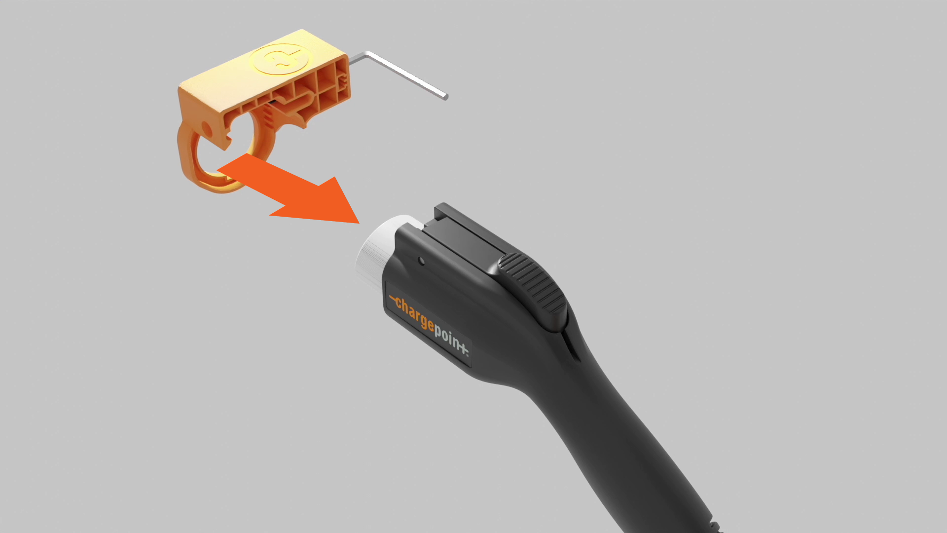
Loosen the drive bolt 5-10 revolutions and remove the connector from the tool.
-
Use the hex wrench to push the guide pin out.

-
Remove the broken latch and spring.

-
Install the spring by placing one end onto the plus-shaped indent of the replacement latch.

Gently align the other end of the spring with the circular indentation in the connector. Line up the pin holes in the latch and connector.
If the spring is not set properly, it might pop out and get damaged when the latch is depressed.
-
Insert the guide pin into the latch to hold the pieces together. Squeeze the latch to ensure the spring functions as intended.

-
Use the hex wrench to loosen the drive bolt. Insert the latch pin fully into the pin slot.

-
Insert the J1772 connector into the repair tool and press into place until the guide pin hole aligns with the exit hole.

-
Use the hex wrench to tighten the drive bolt. The guide pin will slowly extend from the exit hole. If you feel too much resistance but don't see the pin move, check your alignment and try again.

-
Tighten the drive bolt until the guide pin fully extends from the exit hole. Remove the pin by hand.
Keep the guide pin, so you can use the tool to repair another connector.

-
Loosen the drive bolt 5-10 revolutions, then remove the connector from the tool.

Prepare the Charging Cable for Use
To prepare the charging cable for use, complete the following steps:
-
Extend the charging cable to its full length to remove any kinks or twists.
-
Wrap the charging cable over the top of the charging station.
-
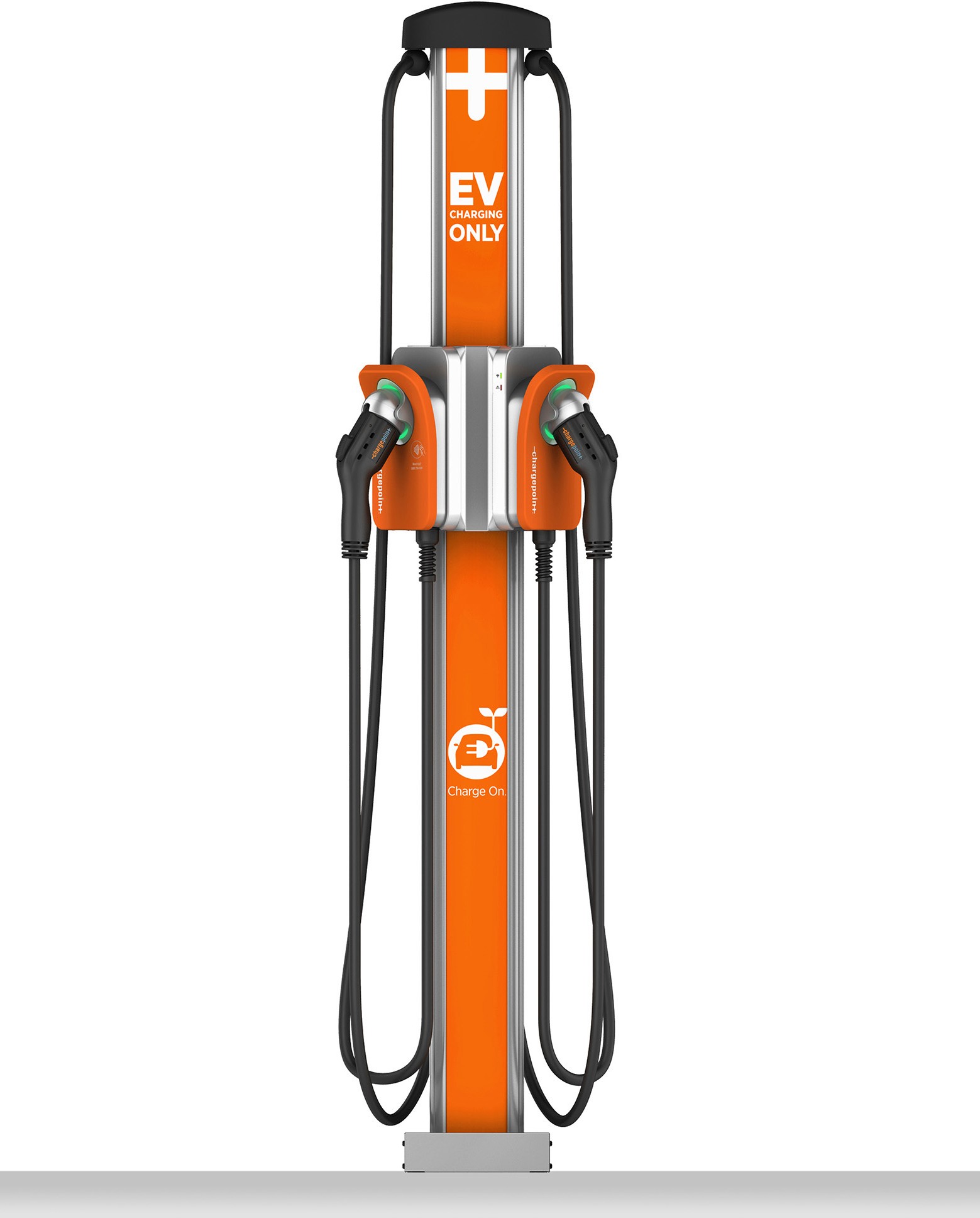
Place the connector back into the holder on the station. If the connector locks in place and charges a vehicle, then it has been successfully repaired.
Restore Power
To restore power, complete the following steps:
-
Restore power to the station at the circuit breaker.
-
Verify that the charging cable now functions by starting a test session and configure the following steps:
-
Initiate a charging session.
-
Plug the handle into a vehicle.
-
Verify that the vehicle is charging.
-
Insert the connector in its holster.
-
