Power Sharing
As shipped, a CT4000 charging station provides up to 30 A of output power to each charging port. The Power Management Kit (ordered separately) provides two features that you can use to adjust the station’s output power:
-
Power Share allows both ports on a dual-port station to share a single circuit. In a default configuration, a dual-port CT4000 requires two 40 A circuits. With Power Share, both ports can share one circuit.
-
Power Select allows the station to operate at a lower current. When the total current capacity is less than the standard 30 A per circuit, you can use Power Select to configure the station to operate at a lower current.
Kit Contents
-
Power jumpers
-
Electrical Rating Labels
Install Circuit Sharing Jumpers
Circuit sharing jumpers are included with all charging stations and are required in each of the following scenarios:
-
Single circuit installations to supply power to dual port stations
-
Single port stations
Jumpers are included with all charging stations.
- Push the black tab (a) on the terminal block to release the terminal block cover.

-
Slide the cover up until it locks into the raised position.
-
Insert the jumpers into the slots located near the upper edge of the terminal block.
-
Use a large flat blade screwdriver to firmly press each jumper until you feel it lock into place.
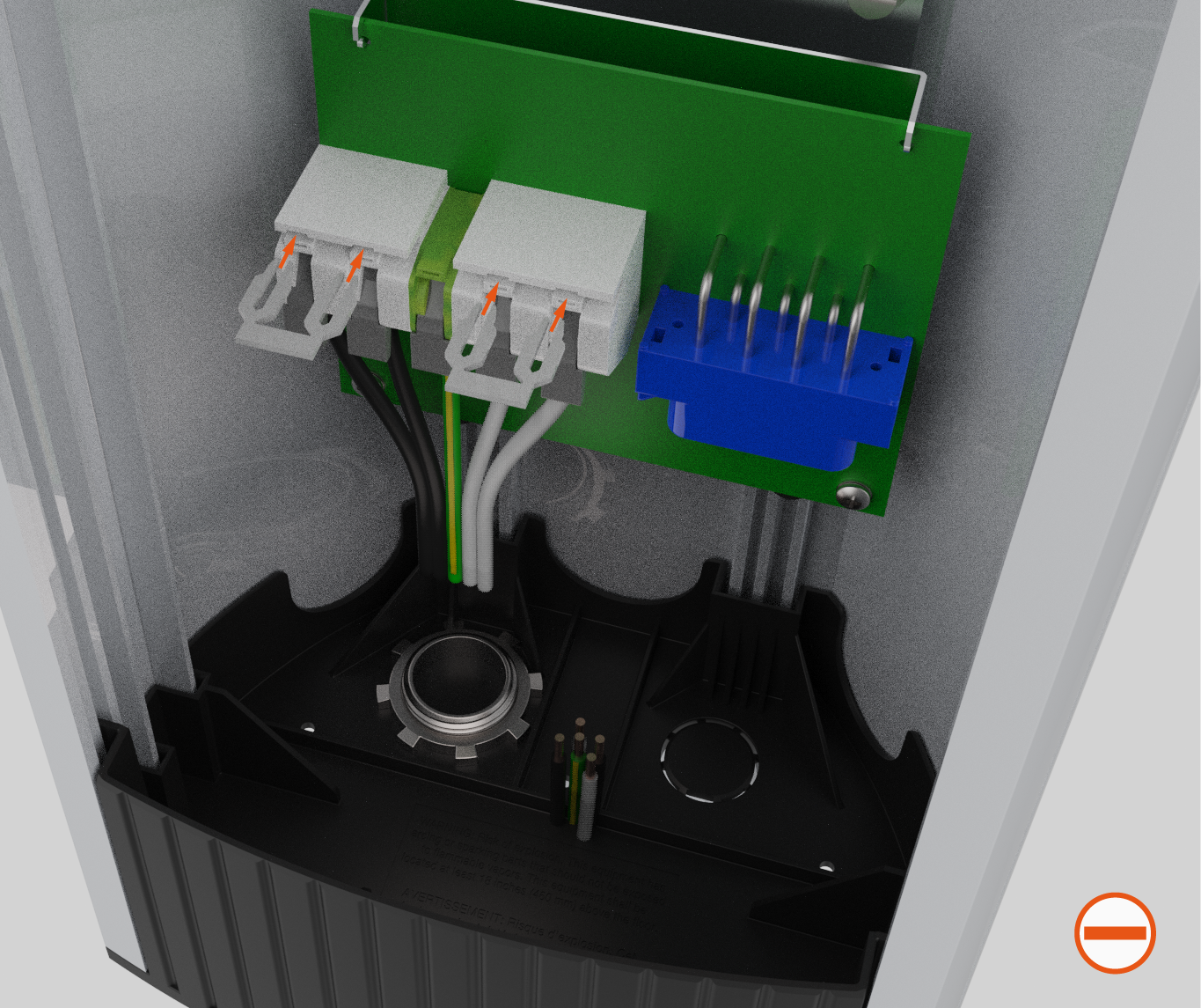 Do not terminate wires on either of the two specific terminals that are being fed by a jumper.Ensure both jumpers are fully seated. Each jumper should be inserted so that it recedes approximately 3 mm (0.118 in) below the outer surface of the terminal block, as shown. If they are flush, they are not fully inserted.
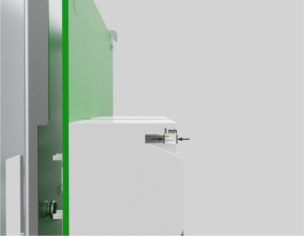
-
To connect the ground wire:
-
Lift the white lever on the terminal block for the ground connection (center).
-
Insert the ground wire into the terminal block.
-
Push the lever down until it clicks and locks in the fully closed position.
-
-
To connect the L1 and L2 wires for the right port:
-
Lift the white levers on the terminal block for the L1 and L2 connections.
-
Insert the L1 and L2 wires fully into the terminal block.
-
Push each lever down until it clicks and locks in the fully closed position.
-


- Use copper conductors only.
- Do NOT provide GFCI
 Ground-Fault Circuit Interrupter protection at the panel. The CT4000 has built-in GFCI Ground-Fault Circuit Interrupter protection.
 - Use breakers rated at 40 A (or lower, if you are configuring the station to operate at a lower current capacity as described on the following page).
- In areas with frequent thunder storms, add surge protection at the service panel for all circuits.
- Use new circuit breakers only. Used breakers can damage equipment and cause a fire risk.
- Ensure all power and ground connections, especially those at the breaker, are clean and tight. Remove all oxide from all conductors and terminals before connecting wiring.
Station installation
-
Install the head assembly and top cap as per Install Head Assembly and Top Cap.
-
Power up the station. If the station displays the Installation Wizard, follow the onscreen instructions to enable Power Sharing. If the station does not display the Installation Wizard, configure Power Sharing using the Service Menu as follows.
-
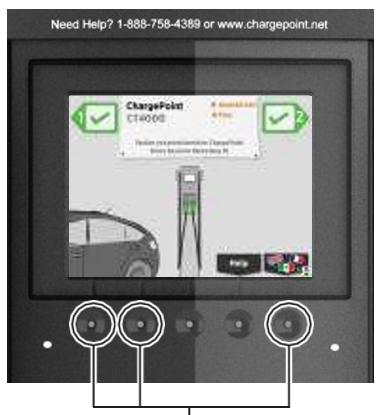
If the Installation Wizard does not display upon power up, simultaneously press and hold these three buttons for two seconds to display the Service Menu on an unactivated station.
-
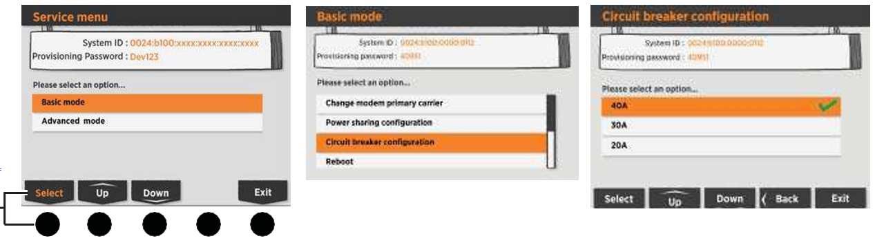
Display the station’s Service Menu:
-
if the station is not activated on ChargePoint, simultaneously press and hold the two leftmost buttons and the rightmost button for two seconds.
-
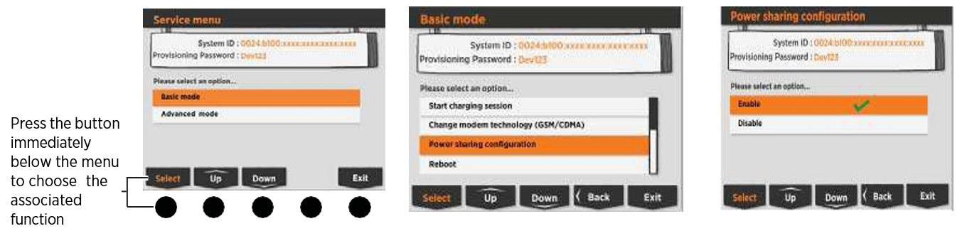
if the station is activated on ChargePoint, scan your ChargePoint Service card. Select Basic mode.
-
-
Scroll down to select Power Sharing Configuration. Select Enable.
-
Select Exit to leave the Service Menu.
-
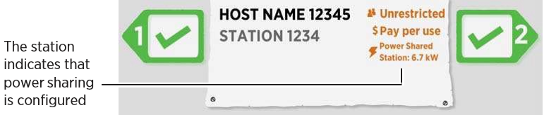
Confirm that the station’s display indicates that power sharing has been configured.
Configure Power Select
-
Power up the station.
-
If the station displays the Installation Wizard, follow the onscreen instructions to enable Power Select. If the station does not display the Installation Wizard, configure Power Select using the Service Menu as described below.
-
Display the station’s Service Menu:
-
if the station is not activated on ChargePoint, simultaneously press and hold the two leftmost buttons and the rightmost button for two seconds.
-
if the station is activated on ChargePoint, scan your ChargePoint Service card. Scroll down to select Circuit Breaker Configuration.
-
-
Choose the breaker size that matches what is installed for the station.
-
Select Exit to leave the Service Menu.
If you make an error when using the Installation Wizard, your ChargePoint Network Manager can change the station’s settings by logging into ChargePoint, selecting the station from the Manage Stations page, selecting the Configuration tab, and then clicking Edit to modify the station’s Power Sharing and Power Select settings. -
If the station must be reconfigured using the Installation Wizard, contact chargepoint.com/support to have the station reset to its factory default configuration.
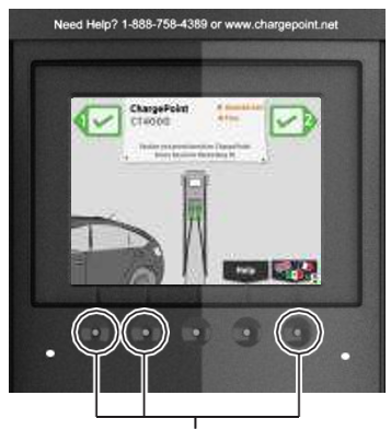 If the Installation Wizard does not display upon power up, simultaneously press and hold these three buttons for two seconds to display the Service Menu on an unactivated station.Press the button immediately below the menu item to choose the associated function.
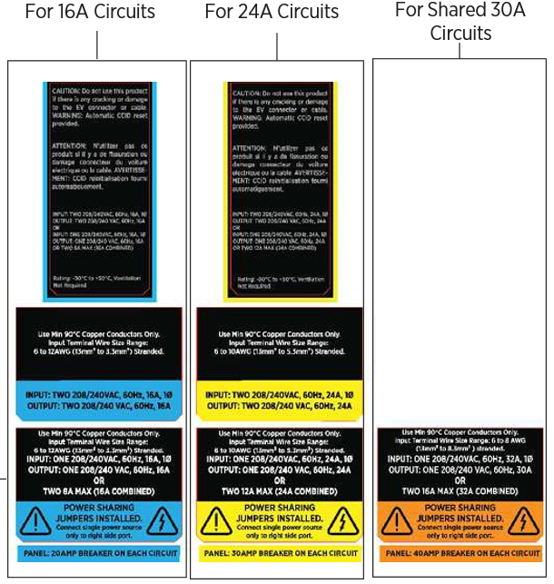
Apply the Electrical Rating label
-
Choose the appropriate label
-
Apply a label to the left side of the terminal block cover, just above the terminal block
 Leave the terminal block cover in the raised position to facilitate connection of the head assembly.
 -
Apply a label to the top cap

-
Apply the corresponding label to the right side of the Top Cap, behind the cable exit.
