Install the Pedestal
Confirm that the location preparation is suitable. You should see the following:
-
Four bolts protruding from the concrete.
-
If the location has concrete but does not have bolts, go to Install Pedestal Bolts.
-
If the location does not have concrete, you need to pour concrete. Contact ChargePoint Support to purchase a Concrete Mounting Kit.
-
-
The bolt position must be consistent with the bolt pattern template provided below.
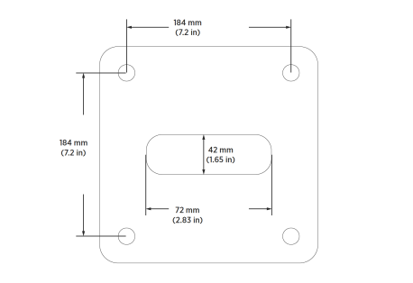
-
Conduit stub-up measuring approximately 0.3 m (1 ft) above the concrete surface.
-
Approximately 1.3 m (51 in) of service wiring extending above the concrete surface.
Install Pedestal Bolts
Read this section only if you need to install bolts to support the pedestal in existing concrete.
If the pedestal location has bolts, go to Mount the Pedestal.
To safely mount a ChargePoint charging station, the concrete must be at least 150 mm (6 in) thick. At this thickness, all of the mounting bolts must be positioned as follows:
-
At least 380 mm (15 in) from the front edge
-
At least 300 mm (12 in) from the side edges
-
At least 150 mm (6 in) from the rear edge of the concrete slab
Tools Needed
Electric hammer drill with 12 mm (1/2 in) or larger chuck.
The following table lists and describes the tools that you will need.
|
Quantity |
Description |
Purpose |
|---|---|---|
|
1 |
Aerosol, any angle spray duster, 235 ml (8 oz) |
Clean drilled holes. (Compressed air or vacuum will also work.) |
|
1 |
Slow spiral round-shank masonry drill bit
|
Drill 16 mm (.63 in) holes in concrete. (The holes must be at least 100 mm (4 in) deep.) |
|
1 |
Drill bit for concrete embedded rebar, round (if required)
|
Drill 16 mm (.63 in) hole through rebar. |
Bolt Installation Instructions
-
Review the bolt hole pattern and mark the hole locations.
Images are not to scale. Measurements appear in metric units (mm) followed by imperial equivalents (inches).
-
Ensure that the conduit stub-up is at the center of the hole location.
-
Drill four 16 mm (.625 in) diameter holes 100 mm (4 in) deep into the concrete.
Ensure the depth and diameter of each hole is correct.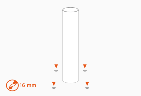
-
Use compressed air, a vacuum, or a brush and remove all dust from the drilled holes.
-
Insert the bolts into the holes.
-
Use a hammer to tap the bolts until they protrude at least 30 mm (1-1/4 inches) above the surface.
Each bolt must extend at least 30 mm (1-1/4 inches) above the surface.
You are now ready to install the pedestal. Continue to Mount the Pedestal.
Mount the Pedestal
-
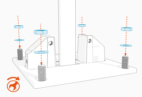
If present, remove the top nut and top washer from each of the four bolts in the pad.
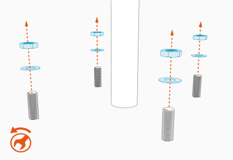
-
Place the pedestal base over the conduit and bolts.
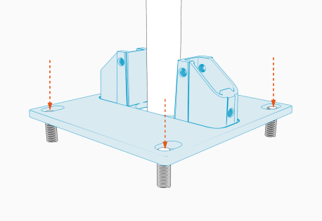
-
Use washers and nuts to secure the base to the bolts.
Torque the top nuts to 100 Nm (73.8 ft-lbs).
-
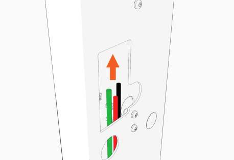
Pull the ground and service wires through the pedestal as it slides onto the base.
The length of the wires, measured from the base of the pedestal, must be at least 1.3 m (51 in).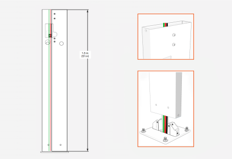
If you plan to install two charging stations on the pedestal, be sure to pull two sets of service wiring (two red wires and two black wires) through.
If the station supports Ethernet, route Ethernet wiring through the pedestal now.
-
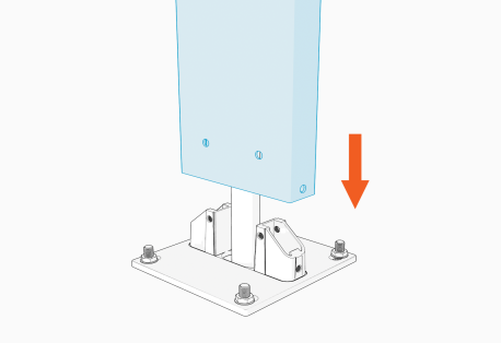
Slide the pedestal onto the base.
-
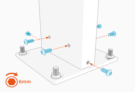
Use a 6 mm hex driver and six screws (provided) to secure the pedestal to the base.
Torque the screws to 20 Nm (14.8 ft-lbs).
Ground the Station and Route the Wiring
-
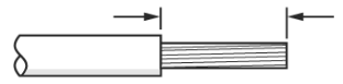
Strip the ground and service wires 13 mm (0.5 inch).

-
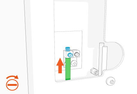
Insert the ground wire (from conduit) into the grounding block in the pedestal.
Tighten the screw on the grounding block to 2.8 Nm (25 in-lb).
-
If you are installing two charging stations on a single pedestal, go to Prepare the Pedestal for Two Charging Stations.
Prepare the Pedestal for a Single Station
If you are installing two charging stations on a single pedestal, go to Prepare the Pedestal for Two Charging Stations.
Complete the following steps for a single charging station:
-
Ensure that there is enough wire (installer provided) to reach from the grounding block to the charging station.
The length of the wires, measured from the base of the pedestal, must be at least 1.3 m (51 in).
-
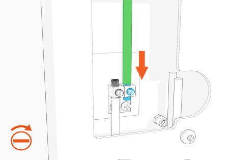
Insert this ground wire into the charging station terminal block.
Tighten the screw on the grounding block to 2.8 Nm (25 in-lb).
-
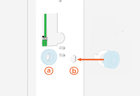
Remove the adhesive backing from the foam ring, then press it firmly over the left-most hole (a) on front of the pedestal.
If you are installing a Flex Series charging station and you're pulling low-voltage wiring (Ethernet, for example) on the right side of the pedestal, install a foam ring on the right-most hole (b).
-
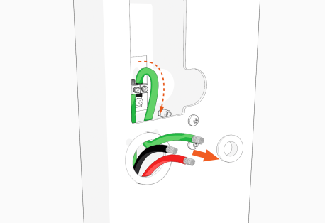
Route the ground and service wires for the first station through the hole on the front of the pedestal.
If you are installing a Flex Series charging station and you are pulling low-voltage wiring (Ethernet, for example), pull the low-voltage wiring through the right-most hole.
-
Go to step 7, Install the Pedestal
Prepare the Pedestal for Two Charging Stations
Complete the steps in this section only if you are installing two charging stations on one pedestal.
-
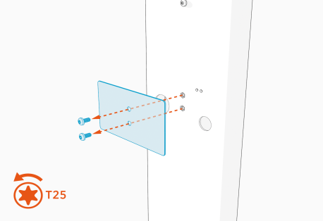
Use a T25 Torx screwdriver to remove the screws and plate from the back of the pedestal.
-
Strip a section in the middle of the grounding wire for both charging stations (installer provided, 8 AWG
 American Wire Gauge maximum) where it will pass through and land in the grounding block.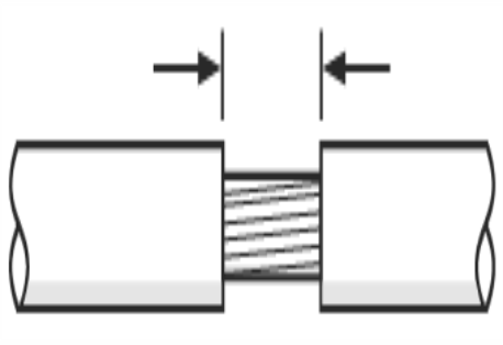
Ensure that there is enough wire to reach from the grounding block to the station terminal blocks.
The length of the wires, measured from the base of the pedestal, must be at least 1.3 m (51 in). -
Insert the ground wire through the open terminal in the grounding block in the pedestal.
Tighten the screw on the grounding block to 2.8 Nm (25 in-lb).
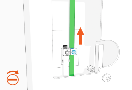
-
Remove the adhesive backing from the foam ring, then press it firmly over the left-most hole (a) on the front of the pedestal.
If you are installing a Flex Series charging station and you are pulling low-voltage wiring (for example, Ethernet) on the right side of the pedestal, install a foam ring on the right-most hole (b).
-
Remove the adhesive backing from the foam ring, then press it firmly over the left-most hole (c) on the BACK of the pedestal.
If you are installing a Flex Series charging station and you are pulling low-voltage wiring (for example, Ethernet) on the right side of the pedestal, install a foam ring on the right-most hole (d) on the BACK of the pedestal.
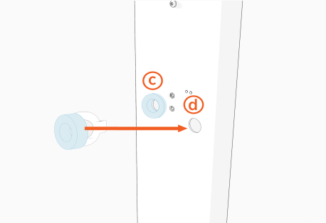
-
Route the lower end of the ground wire through the left-most hole on the front of the pedestal (e). This ground wire connects to the charging station installed in front of the pedestal.
Route the upper end of the ground wire and the service wiring for the second station through left-most hole at the back of the pedestal (f).
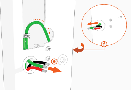
-
Use a T25 Torx screwdriver to remove the two screws from the pedestal.
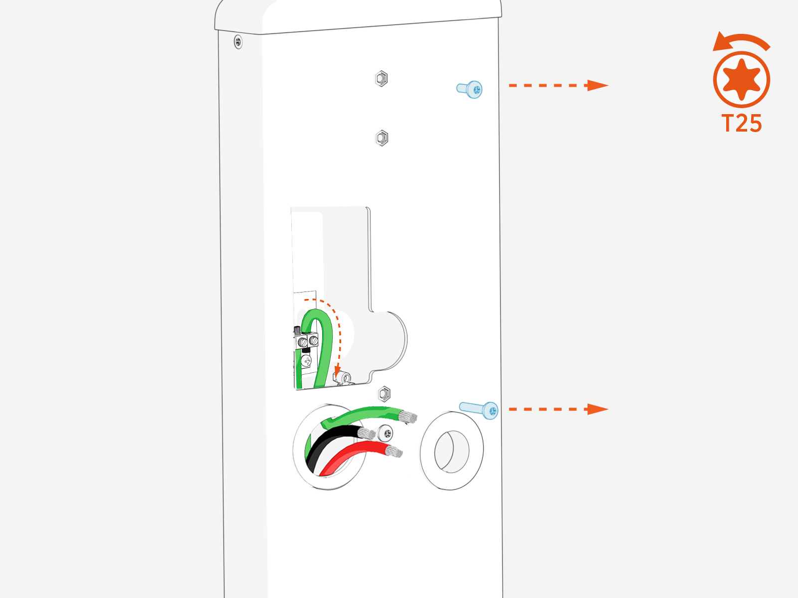
-
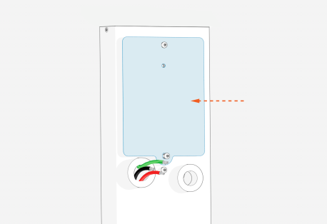
Position the protective plate over the pedestal opening and secure it with the screws.
-
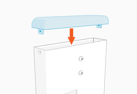
Slide the top cap onto the pedestal.
-
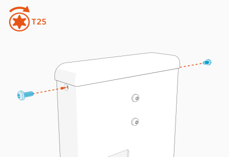
Use a T25 Torx screwdriver and two screws to secure the top cap.
Torque the screws to 1.1 Nm (10 in-lb).
The pedestal installation is complete. Refer to the appropriate charging station installation guide for instructions on mounting and installing the station.
