Conduit and Anchor Bolt Configurations
This section provides information on conduit and anchor-bolt configurations.
Identify Model and Configuration
Conduit and Bolt Locations Vary
Use the appropriate conduits and anchor-bolt locations for your product, configuration, and model.
|
Express Plus |
Express 250 and Express 280 |
|

|

|

|
Wiring Varies
The number and type of wiring is typically different, so check the site drawings for your specific installation.
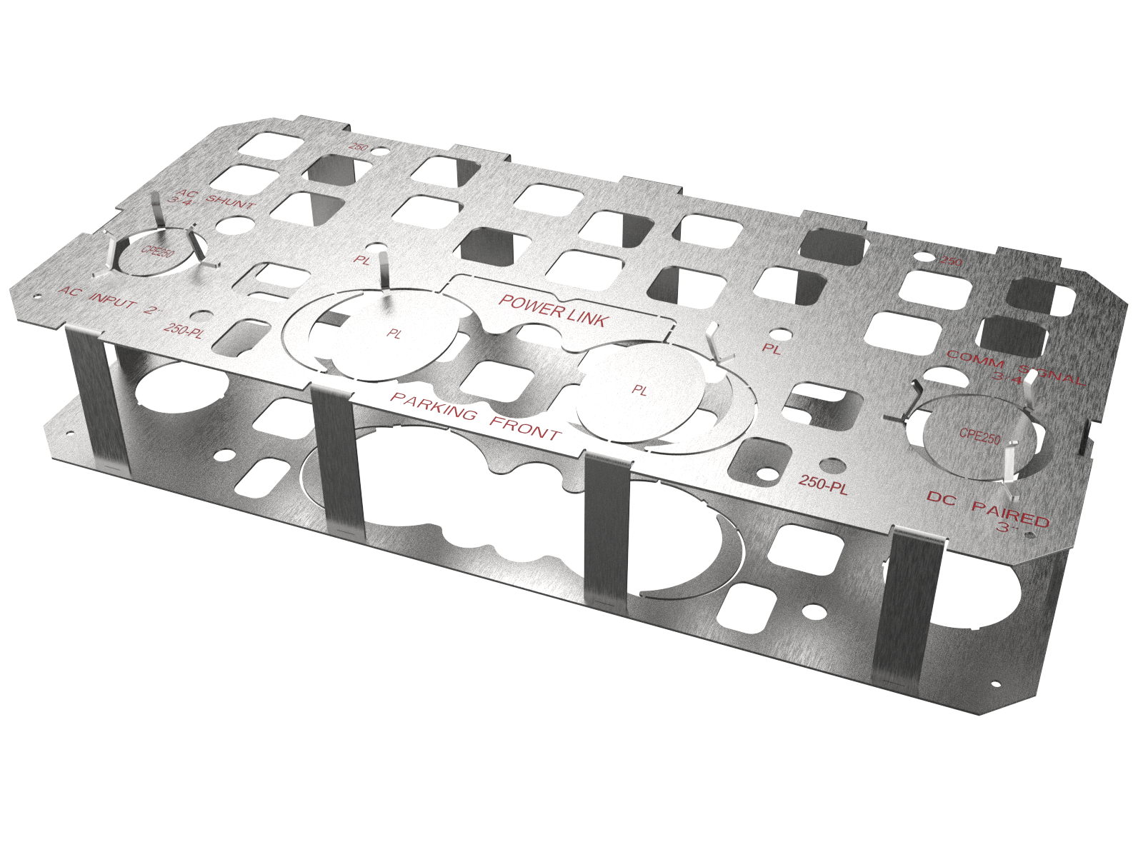
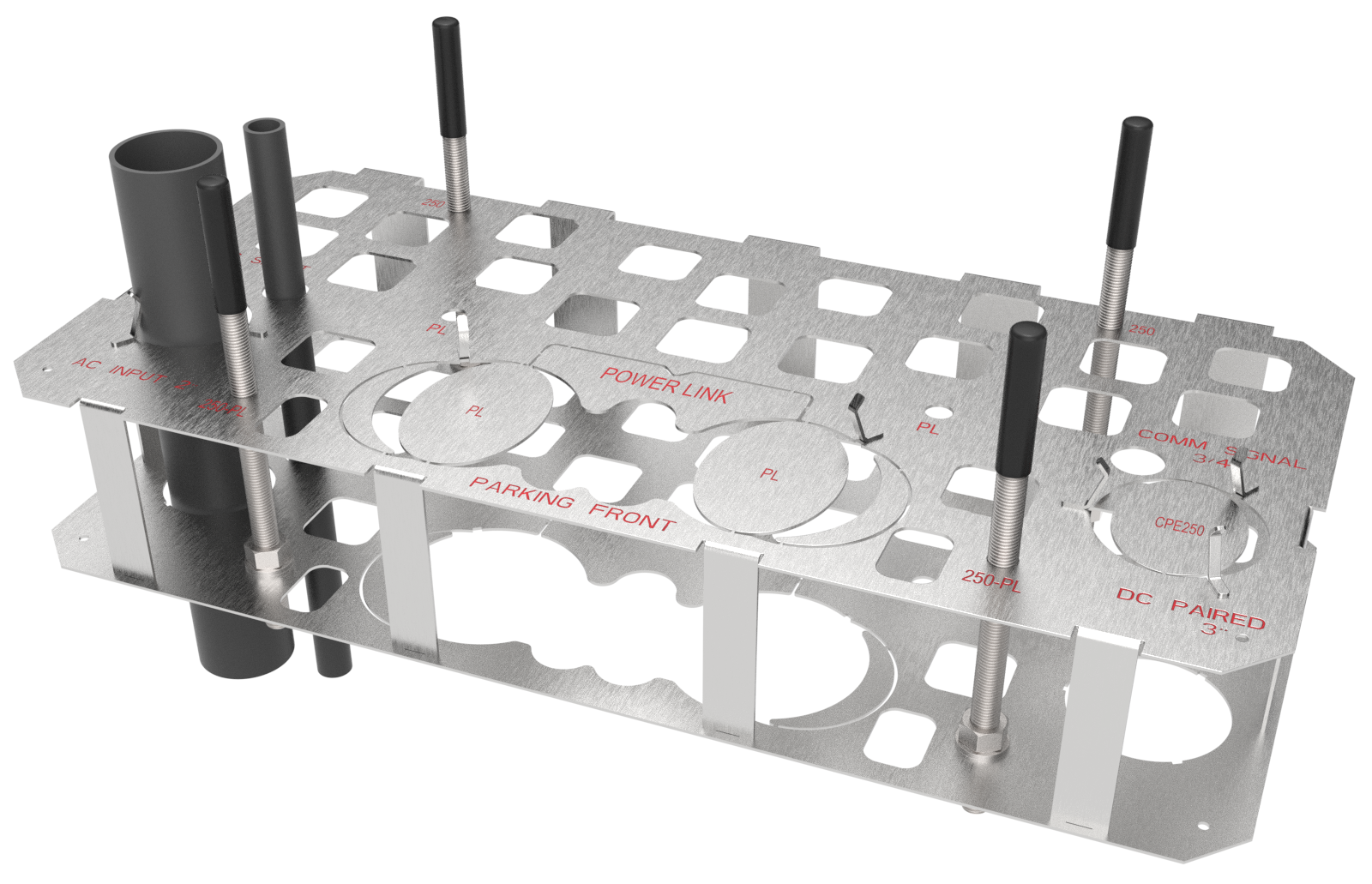
Generic Legend
The generic legend is listed as follows:
| Shape of Opening | Part |
|---|---|
|
Extra small circle |
Anchor bolts (x4)
All stations require four anchor bolts.
|
|
Square |
Concrete embedment and tie-off points (to maintain the position of the template while you pour the concrete and when it is curing) |
|
Small circle |
Conduit for wiring (48 V DC, Ethernet, both of those, or shunt trip) |
|
Medium circle on left side |
Conduit for AC input for Express 250 or Express 280 |
|
Large circle on right side |
Conduit for DC sharing between Paired Express 250 or Paired Express 280 |
|
Extra large circle (front center) |
Conduit for DC input for Power Link |
|
Parking Front |
Marking indicates front edge nearest the parking lot |
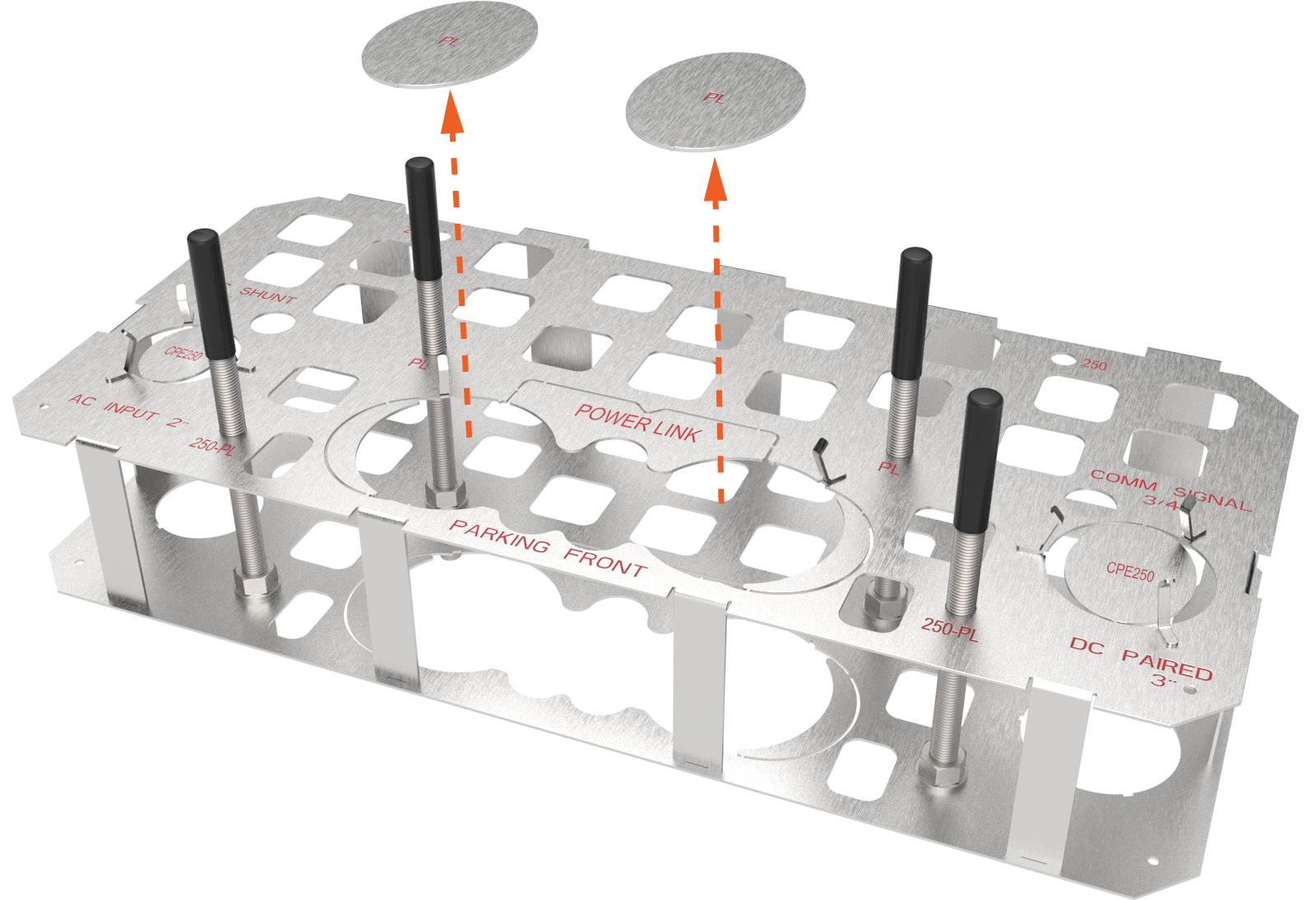
Express Plus Power Link
The Power Link receives DC input from an upstream component called a Power Block or Power Hub that centralizes AC to DC power conversion for multiple stations.
If the quantity listed in the table is a range or option, check the site drawings.
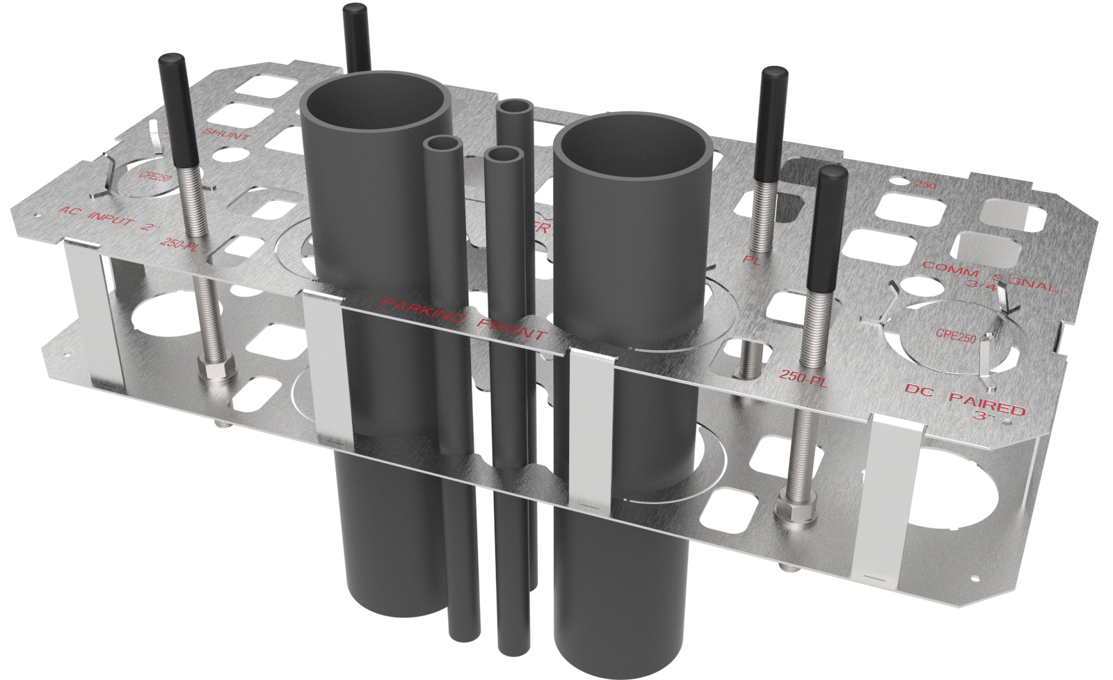
Install four Power Link anchor bolts: two at the front-center edge of the template and two near the middle.

|
Space For |
Max. Size |
Max. Quantity |
|---|---|---|
|
(a) DC input conductors' conduit entry |
Each up to 91 mm (3.5 in) trade size conduit |
2 |
|
(b) 48 V DC wires' and Cat6 Shielded Twisted Pair (STP |
21 mm (3/4 in) trade size conduit NOTE: Check site drawings. |
3 |
|
(c) M16 anchor bolts entry |
76 mm (3 in) above concrete for mounting Power Link |
4 |
|
|
Example only — check site drawings.
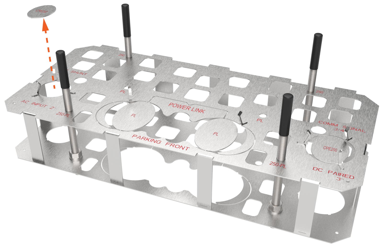
Express 250 and Express 280
Each Express 250 or Express 280 station requires AC power from the site’s electrical panel. That AC conduit includes a ground conductor.
Optional shunt trip wiring can run from the station to the breaker panel. Check the site drawings for this.
Install four anchor bolts, with two at the front (nearest parking lot) and two at the rear of the template.
Standalone or Paired
The standalone configuration uses only the conduit for AC input.
Stations in a paired configuration also run a DC conduit and Ethernet between the paired stations.
|
Standalone |
Paired |
||
|---|---|---|---|
|
AC input conduit |
1 |
AC input conduit |
1 |
|
— |
|
DC shared conduit |
1 |
|
(optional) shunt trip wiring conduit |
1 |
(optional) shunt trip wiring conduit |
1 |
|
Anchor bolts |
4 |
Anchor bolts |
4 |
|
— |
|
Ethernet conduit |
1 |
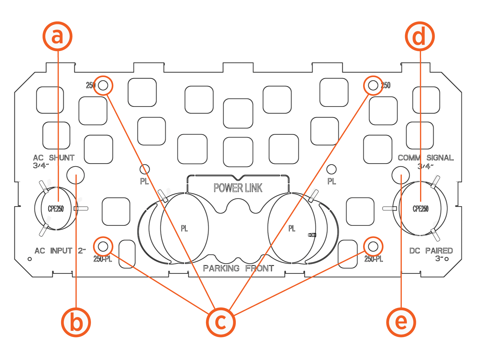
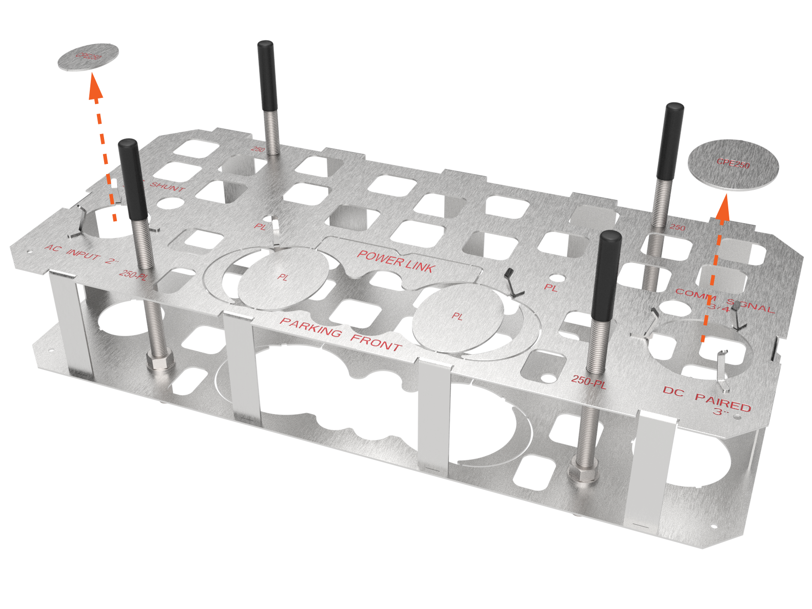
Standalone Express 250 or Express 280 Configuration

|
Route or Break Away for Conduit or Wiring |
Description |
Quantity |
|---|---|---|
|
(a) Breakaway for AC conduit (left side) NOTE: AC conduit may include an AC disconnect switch in the circuit. |
53 mm (2 in) trade size
|
1 |
|
(b) (optional) shunt trip conduit (left side) NOTE: Check site drawings. |
21 mm (3/4 in) trade size
|
|
|
(c) Anchor bolts |
M16 |
4 |
|
|
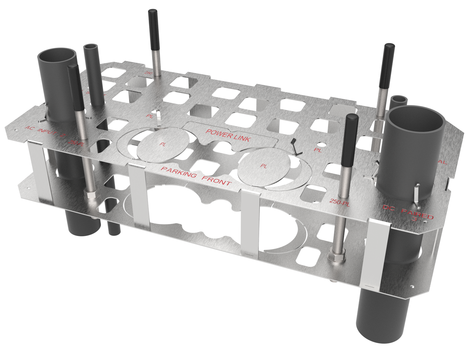
Paired Express 250 or Express 280 Configuration
If two Express 250 or Express 280 charging stations are “paired,” they share DC power to allow faster (higher amperage) charging to a vehicle as needed.
For a paired configuration, follow the diagram. In addition to the Express 250 or Express 280 Standalone Configuration requirements , you must also run two additional conduits between the paired stations: an Ethernet wire for communication and a conduit for DC conductors.
Each Express 250 or Express 280 communicates with ChargePoint via a cellular network. No communication wiring is needed between the station and the building.
|
Conduit or Wiring |
Description |
Quantity |
|---|---|---|
|
(a) Breakaway for AC conduit (left side) NOTE: AC conduit may include an AC disconnect switch in the circuit. |
53 mm (2 in) trade size
|
1 |
|
(b) (optional) shunt trip conduit (left side) NOTE: Check site drawings. |
21 mm (¾ in) trade size
|
1 |
|
(c) Anchor bolts |
M16 |
4 |
|
(d) Breakaway for DC conduit (right side) |
76 mm (3 in) trade size
|
1 |
|
(e) Ethernet conduit (right side) |
21 mm (¾ in) trade size
|
1 |
|
|
