Hang Charging Cable Onto Tool Balancer
Identify if your site plans include a Cable Management Kit (CMK![]() Cable Management Kit) or a tool balancer.
Cable Management Kit) or a tool balancer.
A CMK![]() Cable Management Kit includes swingarms that attach directly to the Power Link 1000 station to manage standard-length (i.e., 4.6 m or 15 ft) charging cables. A tool balancer is attached to a separate structure to manage medium-length (i.e., 7.6 m or 25 ft) charging cables but uses the same ball clamp.
Cable Management Kit includes swingarms that attach directly to the Power Link 1000 station to manage standard-length (i.e., 4.6 m or 15 ft) charging cables. A tool balancer is attached to a separate structure to manage medium-length (i.e., 7.6 m or 25 ft) charging cables but uses the same ball clamp.
Ensure that you implement these requirements. If you fail to do so, the tool balancer may not be properly installed and could cause death, personal injury, or property damage. ChargePoint is not responsible for a design that is not approved by its authorized representatives or that does not conform to these requirements.
Check Post (or Other Approved Structure)
-
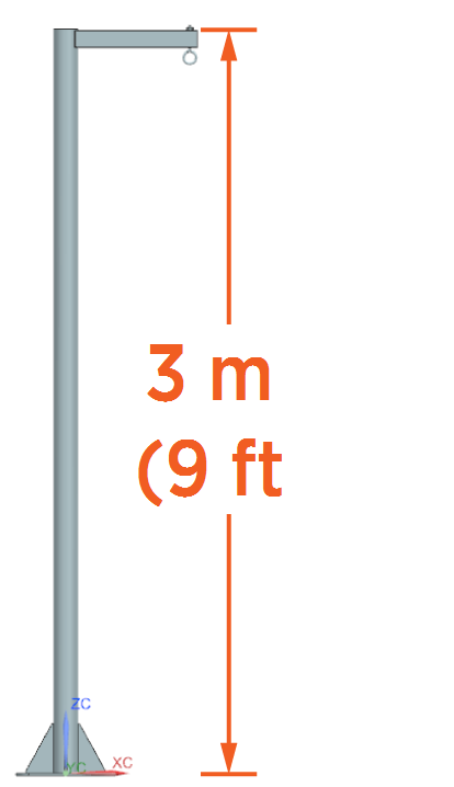
Check that the site meets all requirements of the Site Design Guide and the site drawings, including the following requirements for the post (unless you have another approved structure). If you find any discrepancies, contact your site engineer or construction manager.
-
Post height: 3 m (9 ft 10.5 in)
-
Post and structural arm capacity:
-
Normal capacity: 25 kg (55 lb)
-
Maximum capacity: 200 kg (440 lb) - to prevent deformation of the post in the event the driver drives away with the charging cable plugged in
-
-
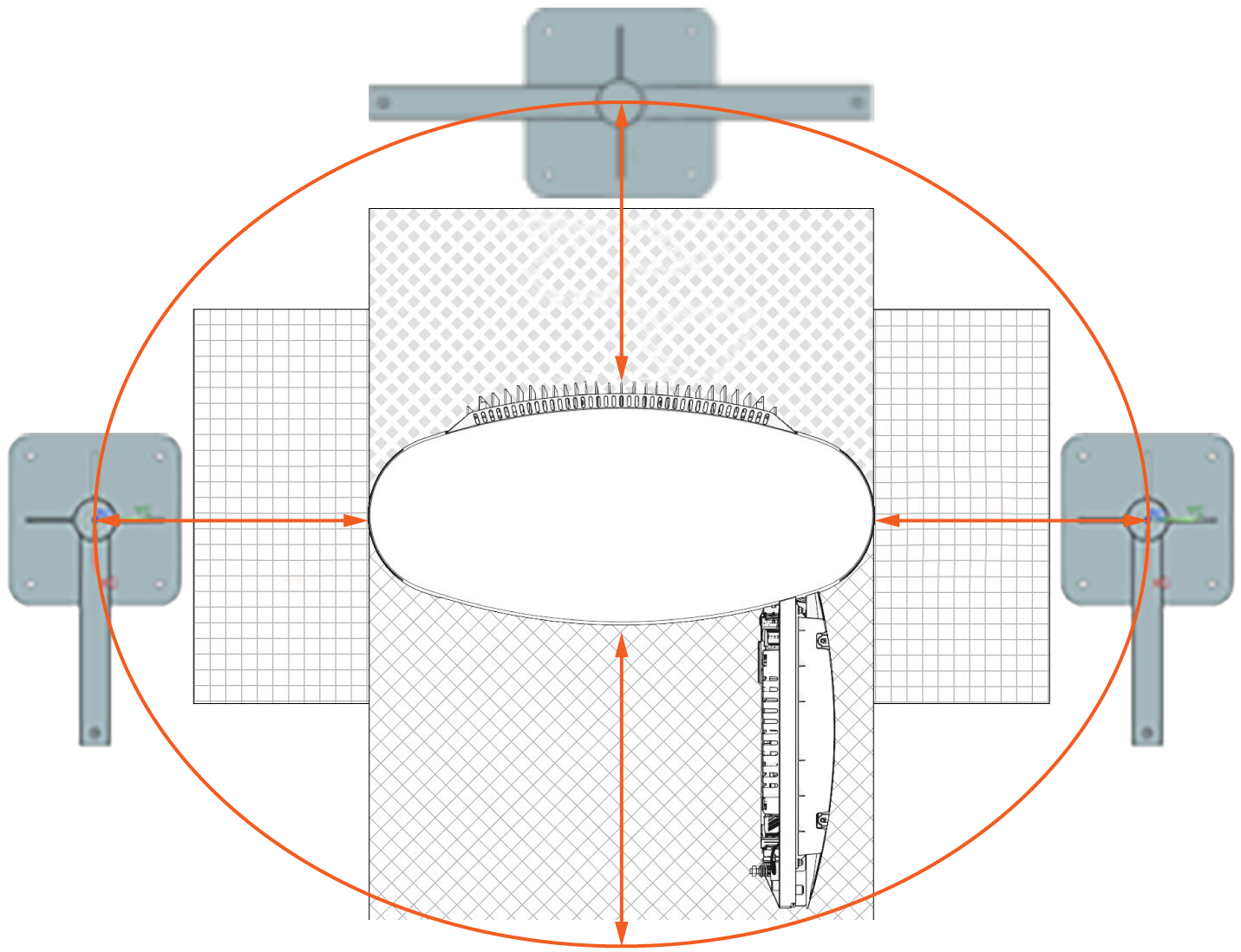
Clearance: Must have enough clearance to open doors or remove covers
-
-
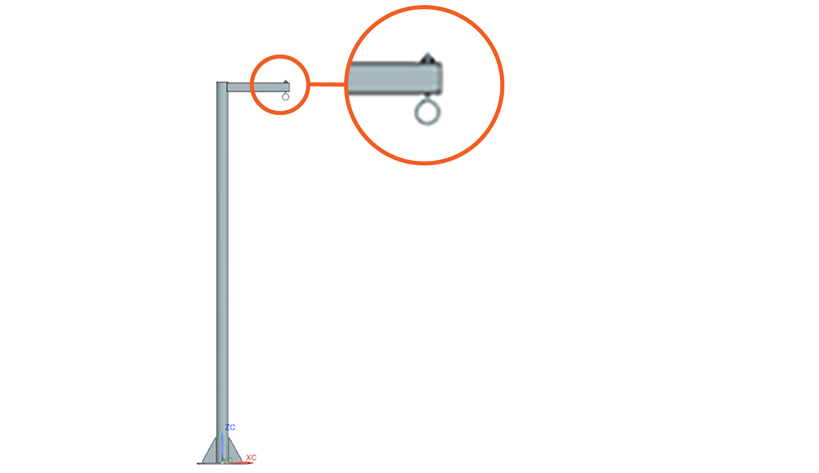
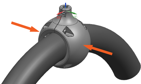
Attach an eye bolt or other appropriate fastener to the structural arm of post at point where you will hang the tool balancer.
Assemble and Hang
Determine the Ball Clamp Type
A. Unassembled Ball Clamp (Tetherball) — Assemble and Position
If the ball clamp is not preassembled and preattached to the charging cable, assemble the ball clamp and eyelet, and position them on the charging cable:
-
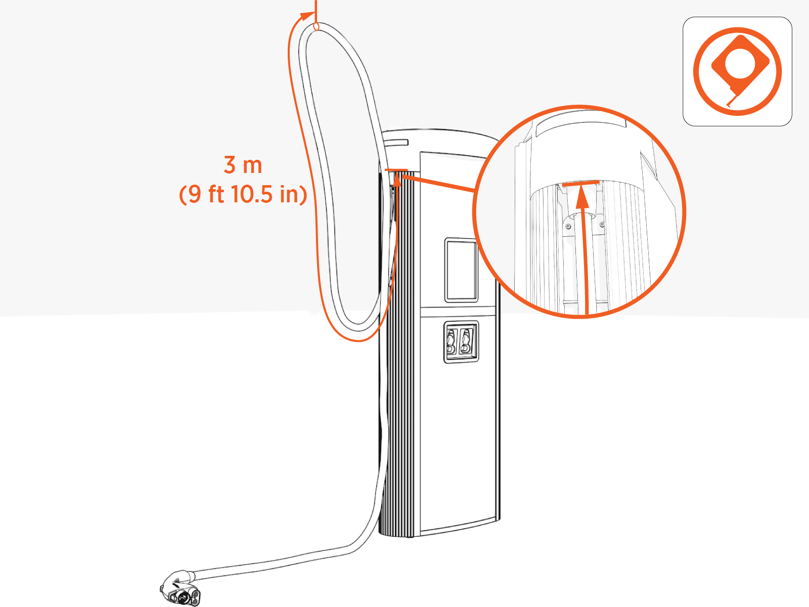
Measure 3 m (9 ft 10.5 in) along the length of charging cable. Start measuring where the charging cable exits the upper side of the Power Link 1000 cable housing exterior.
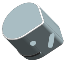
Ball Clamp
-
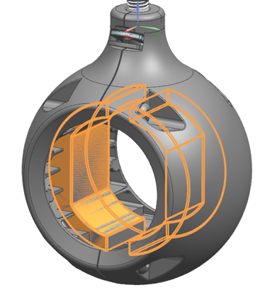
Assemble the ball clamp:
-
Identify the compression pad for the outer diameter of your charging cable. Place compression pad inside half of the ball clamp.
-
Hold spring in position inside half of the ball clamp.
-
Align and position both halves of the ball clamp around the charging cable.
-
Loosely install screws into the ball clamp.
-
Slide the ball clamp to the 3 m (9 ft 10.5 in) point marked on the charging cable (see Step 1).
-
Torque the screws to 2 Nm (1.5 ft-lb).
-
Eyelet
-
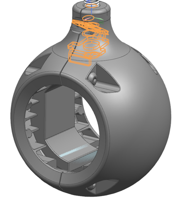
Assemble the eyelet.
-
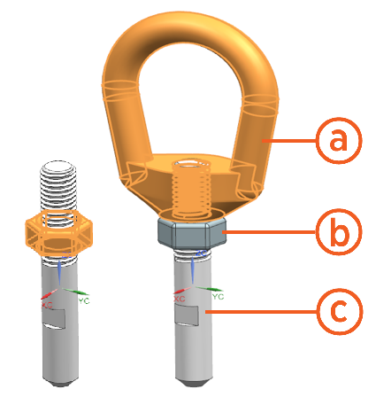
Eye nut
-
M8 nut
-
Pin
-
Install the M8 nut onto the pin.
-
Install the Eye nut onto the pin.
-
Torque the M8 nut to 20 Nm (177 in lb).
-
-
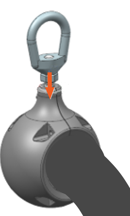
Insert the eyelet into the hole in the ball clamp of the charging cable.
Push-pull to test. The spring in the ball clamp should secure the eyelet. Continue to Set Tension and Attach to Post.
B. Preassembled Ball Clamp — Check Position on Charging Cable
Alternatively, if the ball clamp arrives preassembled and preattached to the charging cable and eyelet, check the position of the ball clamp on the charging cable. Correct if necessary.
-
Measure 3 m (9 ft 10.5 in) along the length of charging cable. Start measuring where the charging cable exits the upper side of the Power Link 1000 cable housing exterior.
-
If necessary, slide the ball clamp to the 3 m (9 ft 10.5 in) point on the charging cable.
Set Tension and Attach to Post
-
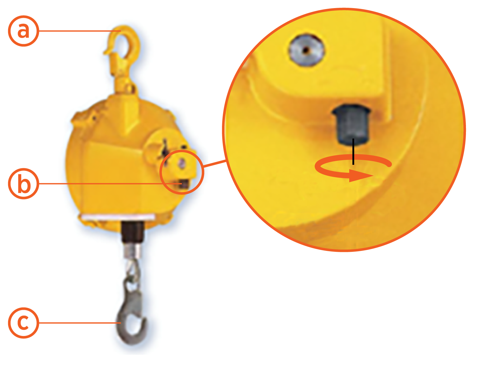
To set tension on the tool balancer, rotate the dial on the tool balancer.
Refer to the table below to see the required tension for a cable rating.
-
Top carabiner hook
-
Dial
-
Bottom carabiner hook
Cable rating 200 A 350 A Required tension 12.5 kg (27.5 lb) 15 kg (33 lb) -
-
Place tool balancer into the rain cover and zip the rain cover.
Make sure to insert the top carabiner hook into the slot in the rain cover and keep the bottom carabiner hook out of the cover.
-
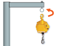
Hang the tool balancer from eye bolt on the post or other approved structure:
-
Hold the top carabiner hook of the tool balancer.
-
Press the top carabiner onto the eye bolt on the post.
-
Ensure the carabiner closes, and the connection is secure.
-
-
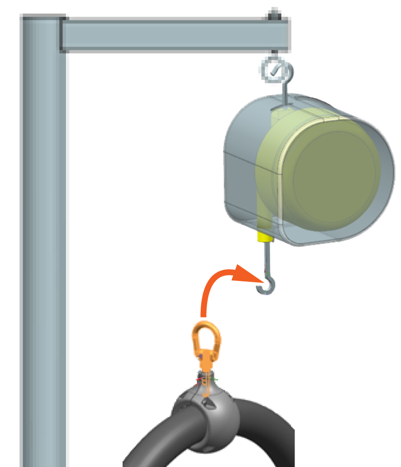
Attach the charging cable ball clamp to the tool balancer:
-
Hold the bottom carabiner hook of the tool balancer.
-
Press the eyelet of the charging cable ball clamp onto the bottom carabiner.
-
Ensure the carabiner closes, and the connection is secure.
-
-
Check that the tension setting on the tool balancer has not changed and is still correct.
CAUTION: The charging cable must be at least 2 cm (0.80 in) above the ground and clear of all nearby obstacles.If the charging cable does not have sufficient ground clearance, incrementally increase the tension setting on the tool balancer.
Contact ChargePoint Support (chargepoint.com/support) if you have questions.
Check Operation
-
Move and extend each charging cable to check that it operates smoothly.
If you find limited motion, contact ChargePoint at chargepoint.com/support.
