Install Swingarms Onto Station and Hang Charging Cable
(Standard Pedestal)
Identify if your site plans include a Cable Management Kit (CMK Cable Management Kit) or a tool balancer.
A CMK Cable Management Kit includes swingarms that attach directly to the Power Link 1000 station to manage standard-length (i.e., 4.6 m or 15 ft) charging cables. A tool balancer is attached to a separate structure to manage medium-length (i.e., 7.6 m or 25 ft) charging cables but uses the same ball clamp.
Install Mast
-
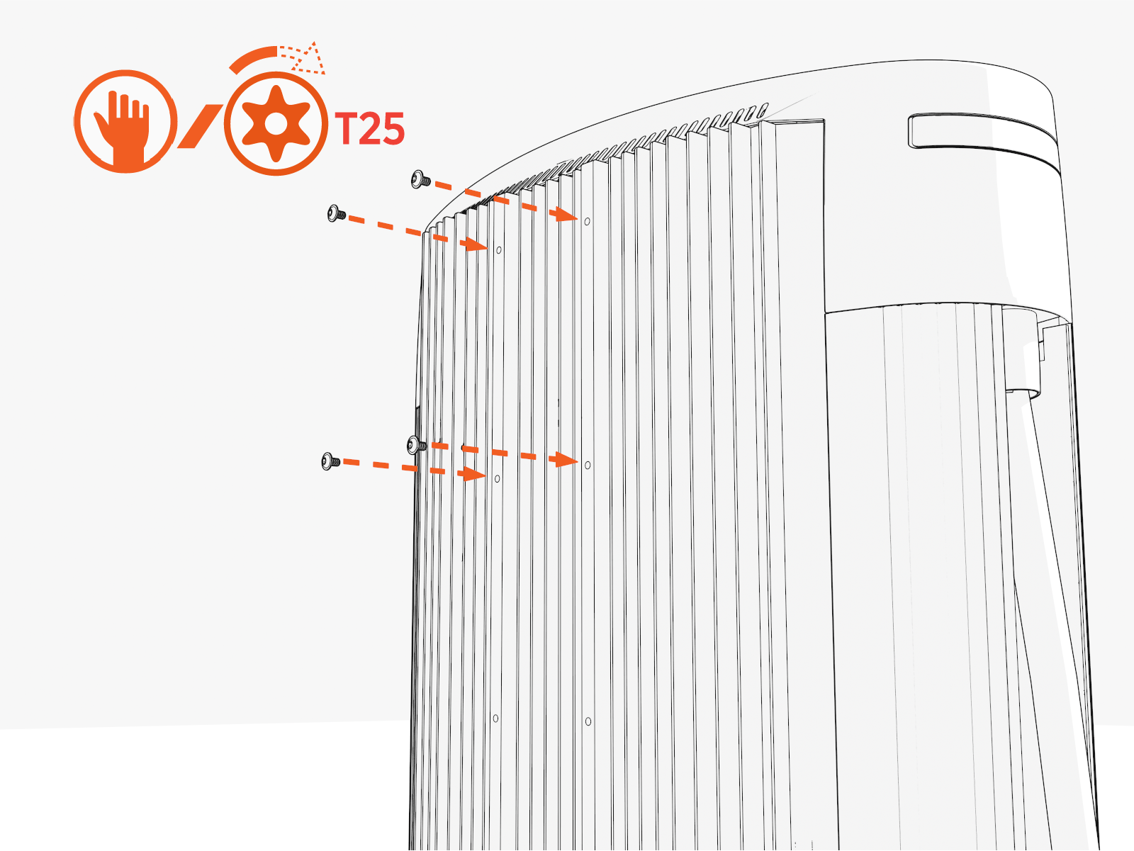
Partially install screws into four upper holes on the rear exterior of Power Link 1000.
-
Hang the mast using the middle and lower keyholes.
Final install height of the CMK
Cable Management Kit should be 2413 mm (7 ft 11 in).The CMK
Cable Management Kit can be lowered 203 mm (8 in) by using the upper and middle keyholes to allow for installations with low overhead clearance.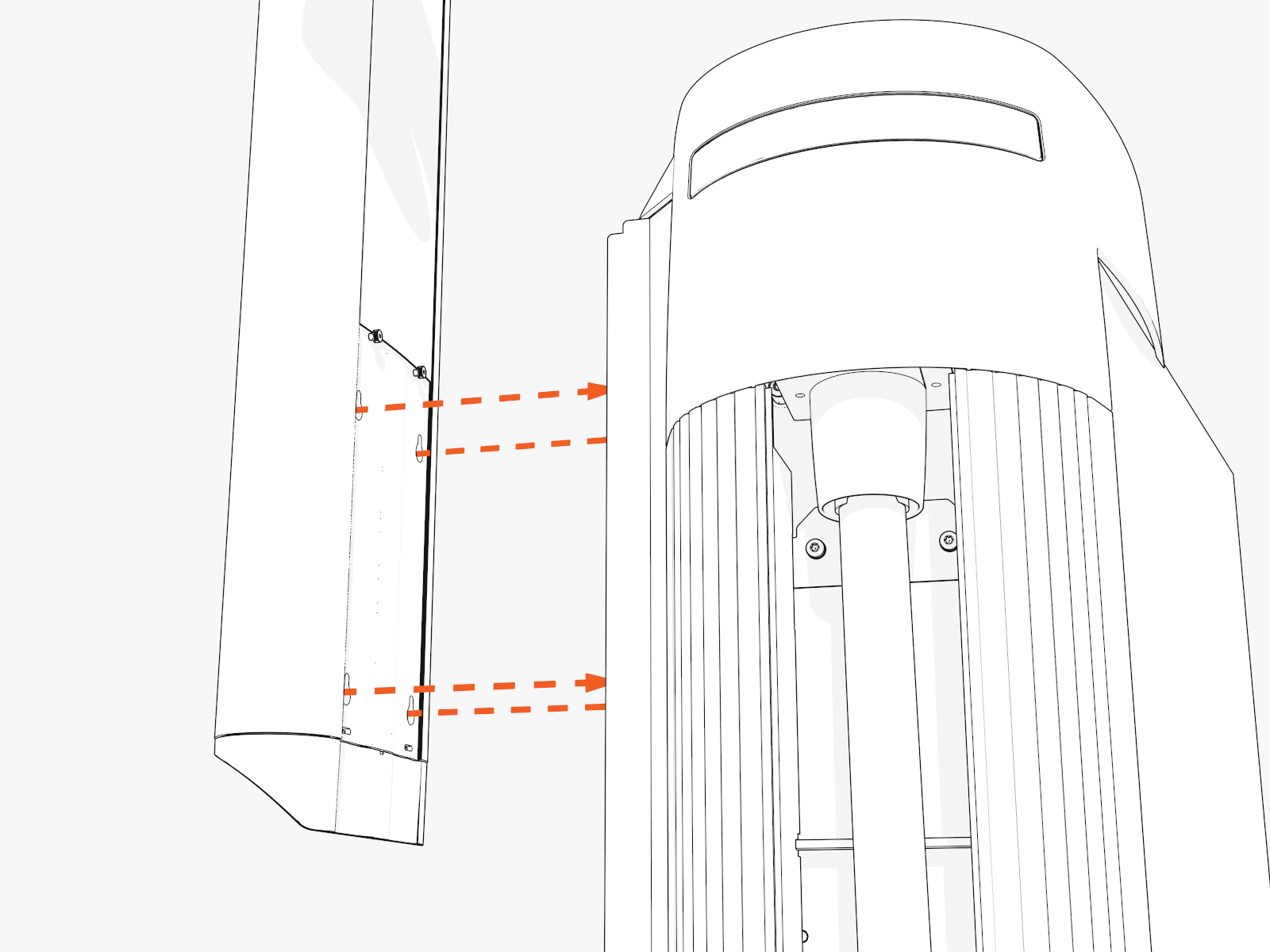
-
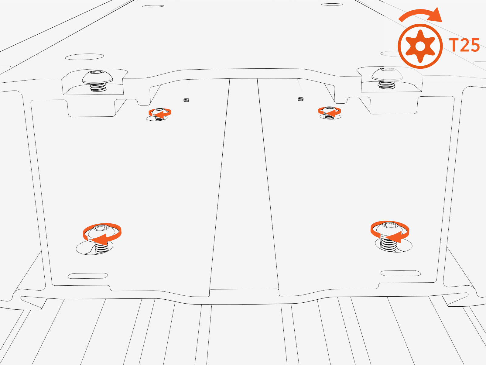
Torque screws (x4) to 5.6 Nm (50 in-lb).
Install Swingarm Assembly
Insert two alignment pins into the bottom center of the swingarm attachment. Position the pins into the top of the mast.
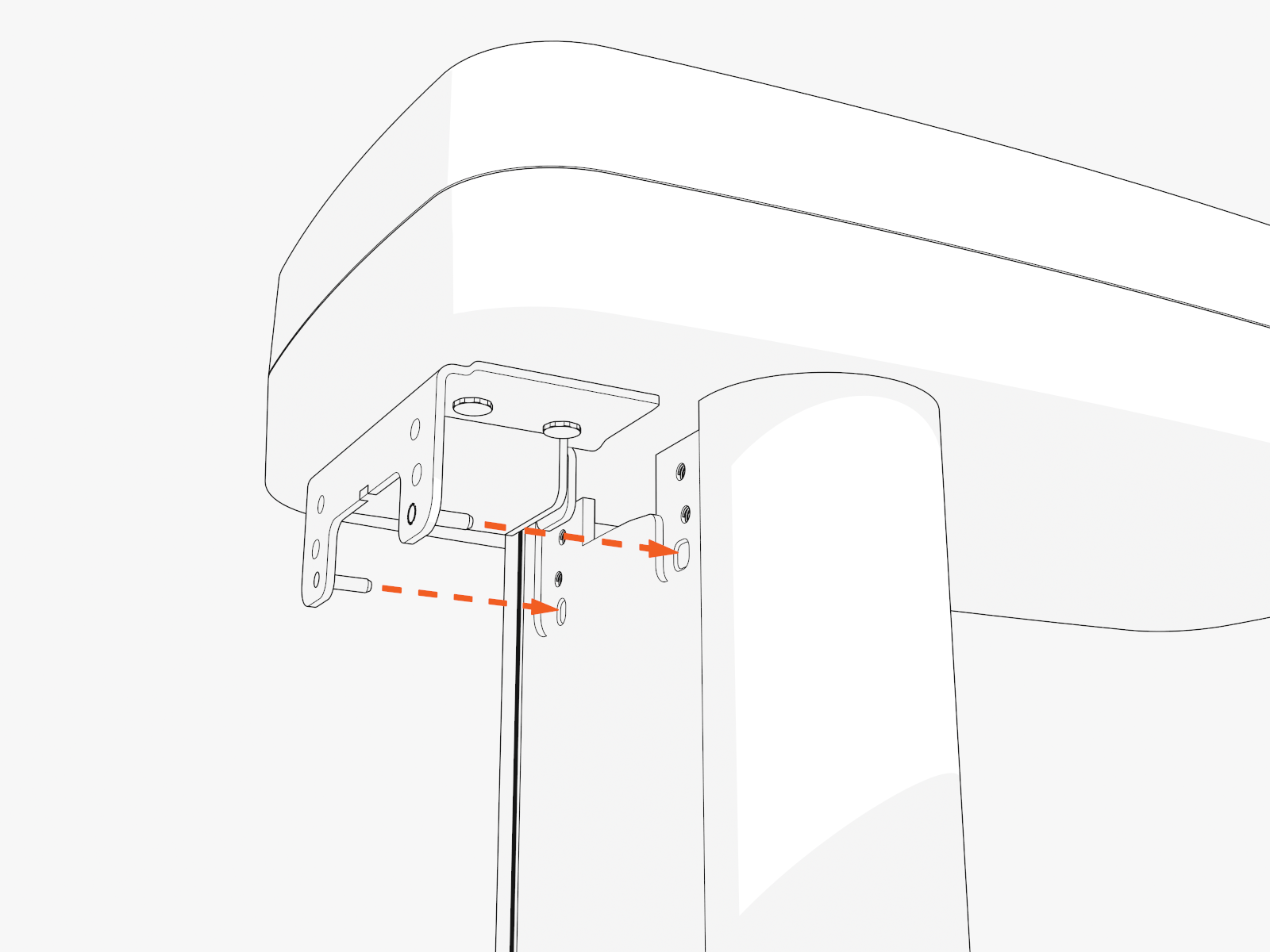
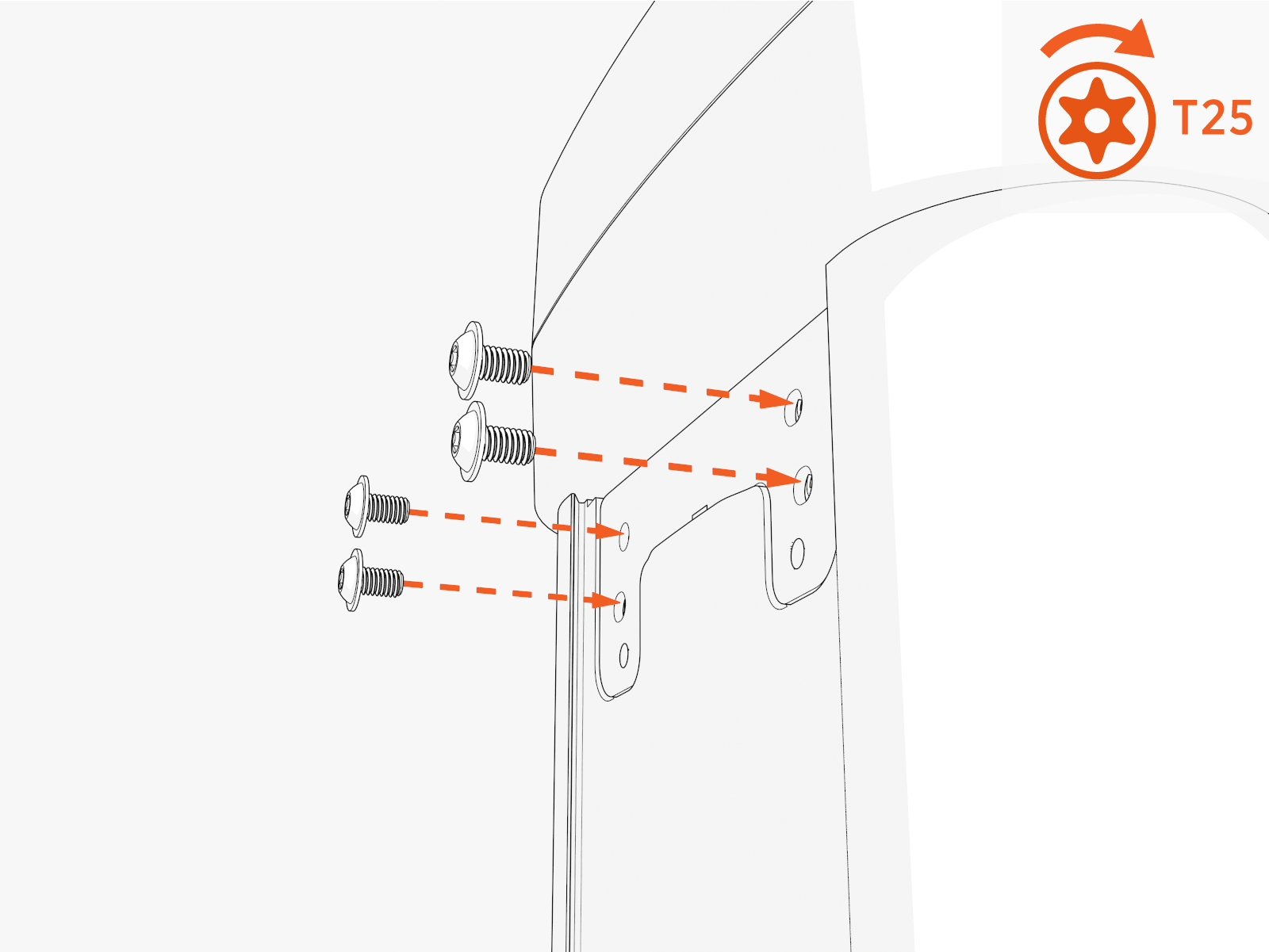
Torque screws (x4 at rear and x1 at front) to 5.6 Nm (50 in-lb) .
Install Covers
-
Install the CMK
Cable Management Kit covers onto the rear of the mast. Bend the cover on the long axis. Slip the edges into the grooves in the mast.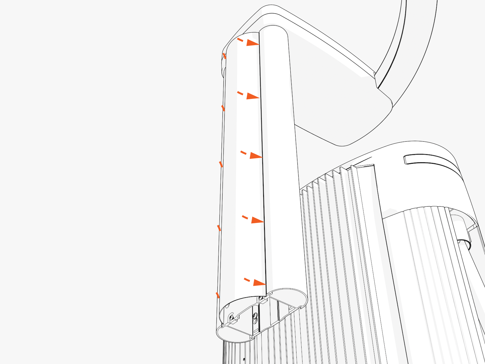
-
Repeat to install covers onto the front of the mast.
Hang the Charging Cable
-
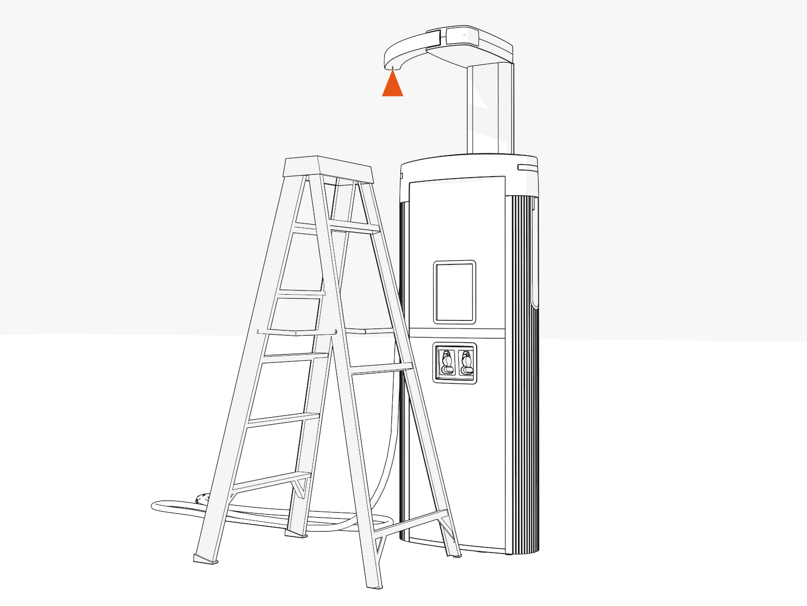
Position the stepladder so that you can reach the hanging point.
-
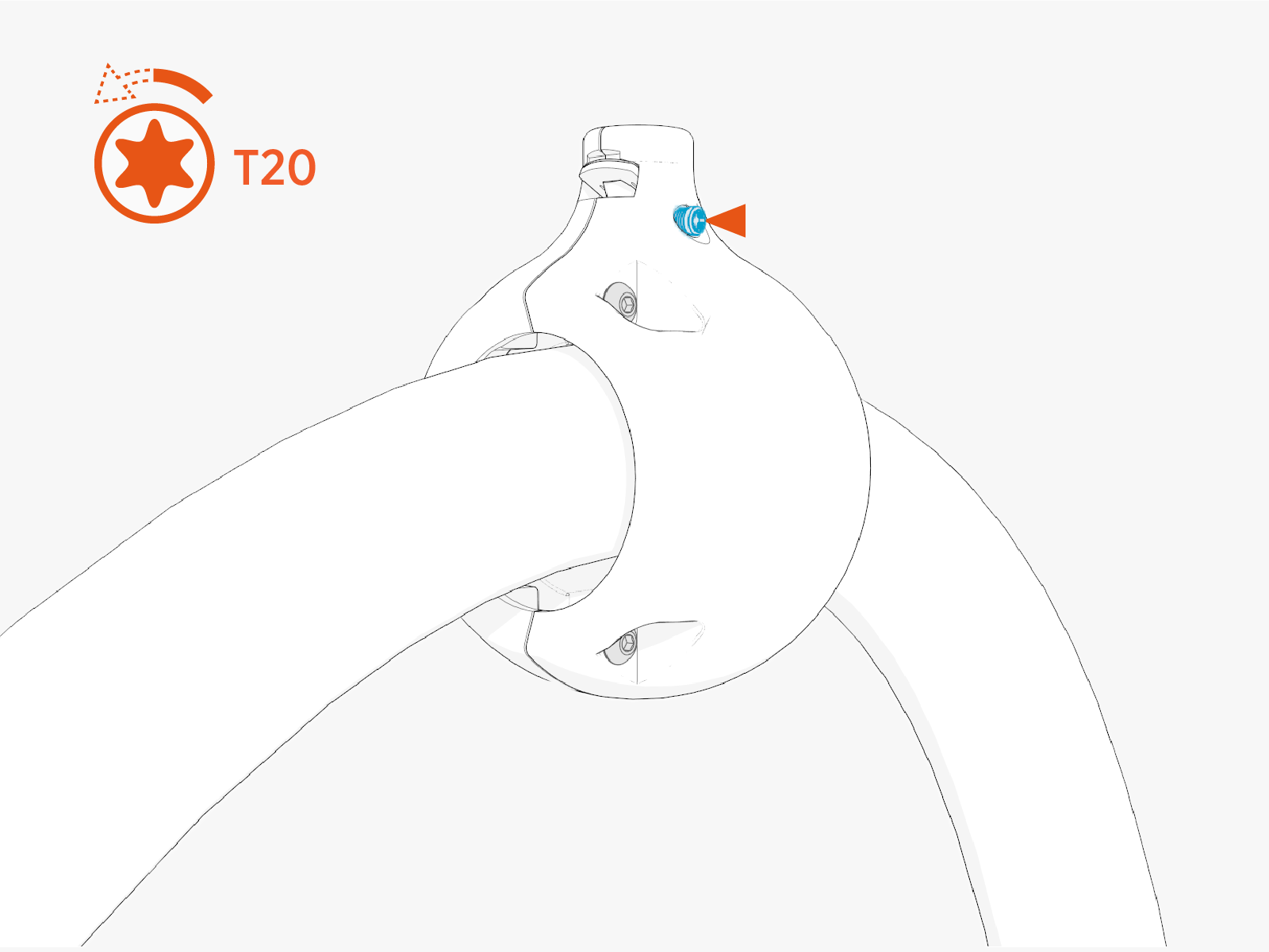
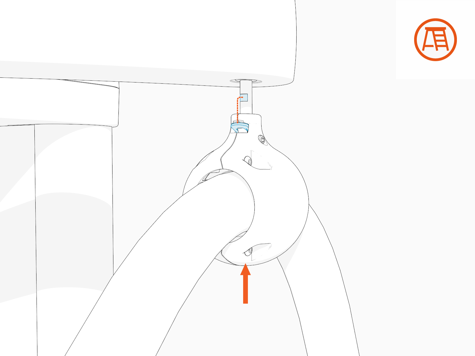
Ensure the screw (if present) on the charging cable tetherball is loose.
-
Align the spring with flat notch on the tether pin and gently push the tetherball onto the pin to hang the cable.
-
If necessary, slide the tetherball to a position on the cable such that the cable doesn't touch the ground when installed onto the CMK
Cable Management Kit tether pin.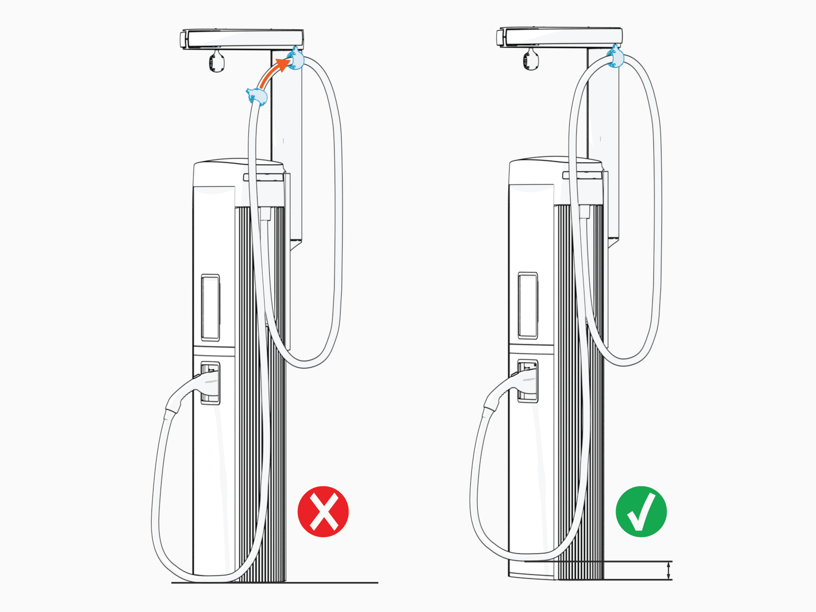
-
Torque the screw to 2.8 Nm (25 in-lb)
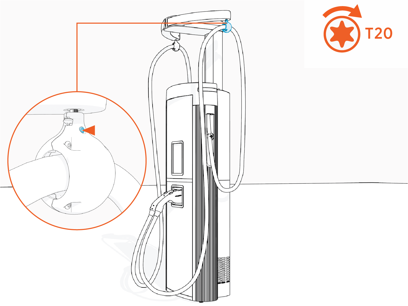
Complete CMK Installation
-
Place each charging cable in the holster.
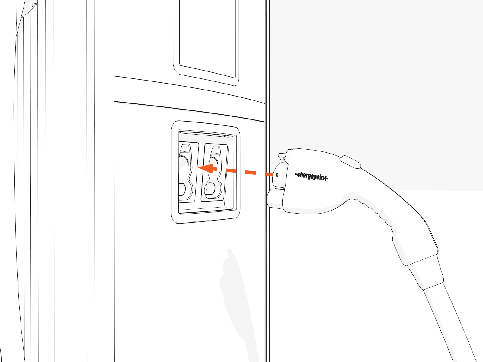
-
Untangle any twists.
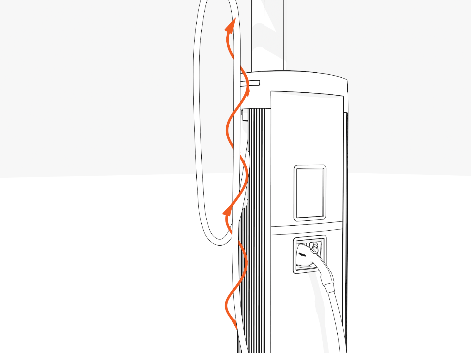
-
Check that the charging cables and swingarms operate smoothly by fully extending and retracting.
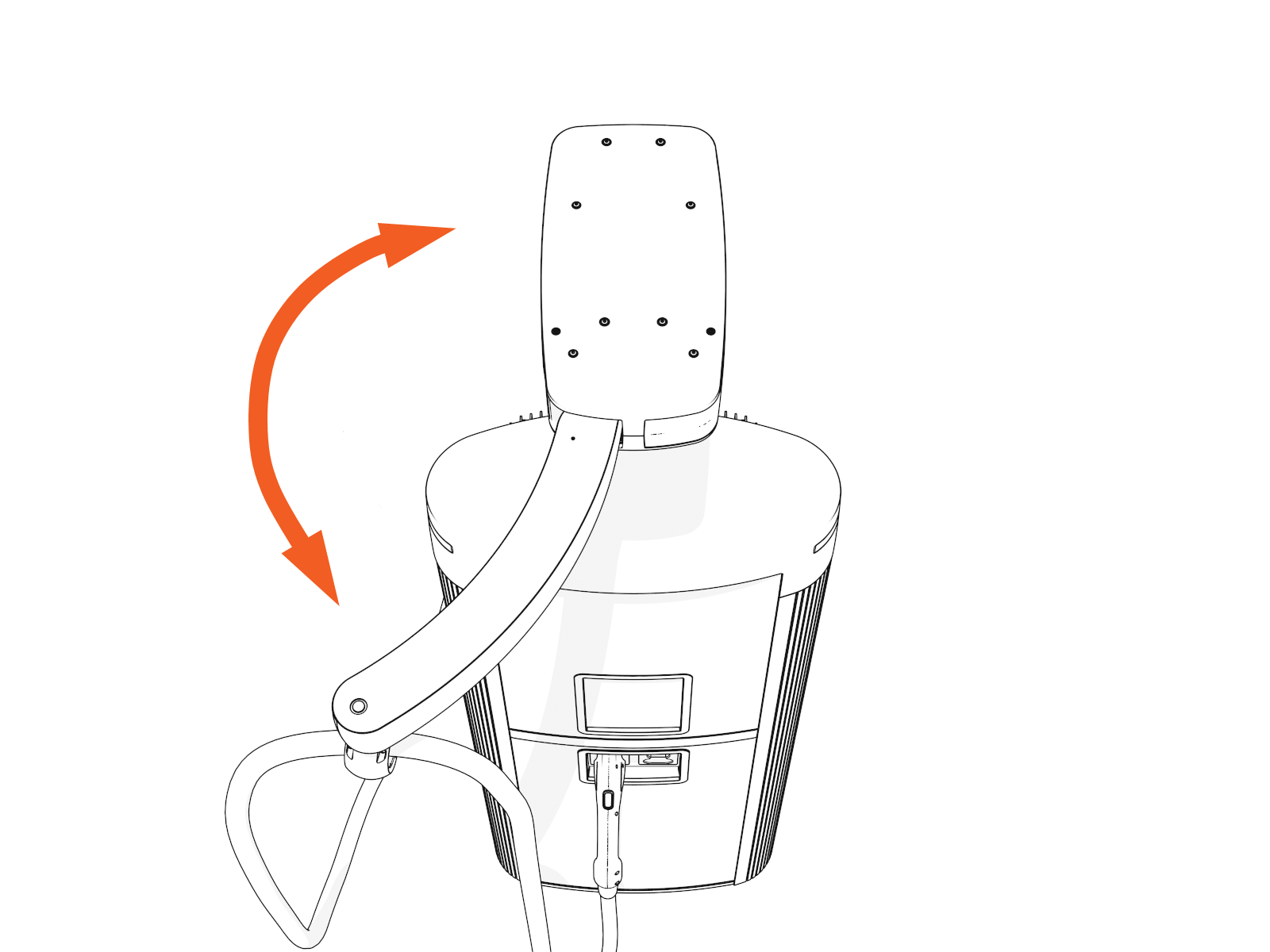
-
If you find limited motion or retraction, contact ChargePoint at chargepoint.com/support.
