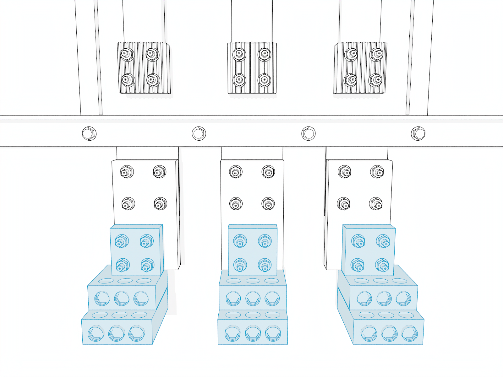
Electrical Design
This section provides electrical design guidelines for Express Solo.
Electrical Supply Requirements
Charging stations are considered continuous load devices (EVs draw maximum load for long durations). Therefore, electrical branch circuits to EV Electric Vehicle chargers must be sized at 125% of the load on each leg of a 3‑phase panel for North American (NA) installations, in accordance with National Electric Code requirements.
When planning multiple EV Electric Vehicle charging stations, it is best practice to segment non-continuous and continuous loads, with all branch circuits for EV Electric Vehicle charging on a dedicated electrical panel assembly with adequate circuit breakers. When sizing new electrical panels dedicated for EV Electric Vehicle charging, all branch circuits must support continuous load.
Express Solo is available in multiple power ratings:
-
In the US: 200 kW, 400 kW, 600 kW
-
In Canada: 225 kW, 450 kW, 625 kW, 675 kW
Each Express Solo requires its own circuit breaker. Recommended breaker sizing is given below. Check with local code for breaker size requirements.
Recommended breaker sizing for the US region (480 V AC):
|
Max. Output Power |
AC Continuous Input Current Rating |
Derating Factor (125% continuous) |
Recommended breaker size |
|---|---|---|---|
|
Max output power 200 kW |
258 A |
323 A |
350 A |
|
Max output power 400 kW |
515 A |
644 A |
700 A |
|
Max output power 600 kW |
769 A |
961 A |
1000 A |
Recommended breaker sizing for the Canada region (600 V AC):
|
Max. Output Power |
AC Continuous Input Current Rating |
Derating Factor (125% continuous) |
Recommended breaker size |
|---|---|---|---|
|
Max output power 225 kW |
232 A |
290 A |
300 A |
|
Max output power 450 kW |
463 A |
579 A |
600 A |
|
Max output power 625 kW |
641 A | 801 A | 850 A |
| Max output power 675 kW |
691 A |
864 A |
900 A |
-
For upstream breakers ≥ 1000 A, provide GFPE in accordance with NEC
National Electric Code and CEC (typically implemented via LSIG breakers). - For breakers < 1000 A, GFPE is generally not required; LSI or thermal-magnetic breakers may be used subject to coordination requirements.
-
Express Solo has a short circuit current rating of 100 kA.
Express Solo is tested to IEC 61000-4-5, Level 5 (6 kV @ 3000 A) standards.
Disconnect and Emergency Shutoff
ChargePoint recommends installing a local AC disconnect switch—separate from the shunt trip wiring—between each cabinet and the electrical panel. A local disconnect is especially important when the main electrical panel or utility room is distant, not within line of sight, or has restricted access.
Express Solo can be ordered with an optional AC disconnect switch. When included, the switch is located on the intake side of the cabinet.
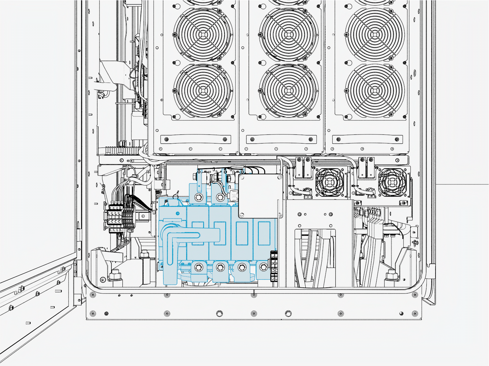
Consult local electrical codes to determine disconnect and emergency shutoff requirements. Recent and upcoming code cycles include significant updates to disconnect and emergency shutoff requirements. Always verify compliance with the latest adopted electrical code.
Transformer Configuration
Refer to the following table for the transformer configuration.
| Transformer Configuration | ||
|---|---|---|
| Parameter | US | Canada |
|
Input rating |
480 V AC, 3-phase, 1000 A, 60 Hz |
600 V AC, 3-phase, 900 A, 60 Hz |
|
Electrical service configuration |
480 V AC 3-phase grounded WYE (Y) configuration
480 V AC 3-phase Delta (D) configuration (corner-grounded Delta transformer) is not acceptable |
600 V AC 3-phase grounded WYE (Y) configuration
600 V AC 3-phase Delta (D) configuration (corner-grounded Delta transformer) is not acceptable |
|
Product connection |
Express Solo must be connected to L1, L2, and L3 (neutral not required) |
|
Shunt Trip Wiring (optional)
Express Solo provides a set of unpowered (dry) contacts to connect to an optional shunt trip device. These contacts are rated to 240 VAC and 6 amps.
Wiring sections to and from Express Solo are deactivated when unsafe conditions are detected, such as unintended cover panel removal. A breaker reset is required any time the shunt trip is activated.
If installed, each Express Solo must be wired to the shunt trip unit of its own upstream circuit breaker. Upstream AC power must be shut off at the panel to remove shock risk inside the Express Solo. All shunt trip behavior is already hard-coded into the Express Solo and has no programmable variables.
Emergency stop devices are governed by local and regional codes and may be required in some sites. If one is required by code or by the site, confirm specifications with your ChargePoint representative.

-
Electrical panel
-
Express Solo
-
Control voltage supply, maximum 240 VAC
-
Shunt trip circuit breaker
-
Shunt trip coil
-
Auxiliary contacts (closed when main contacts are closed)
-
3-phase AC main
-
Express Solo shunt trip contacts, Normally Open (inside the auxiliary power supply, accessible on field wiring terminal block)
-
3-phase Express Solo AC input
Grounding Requirements
-
Express Solo must be connected to a grounded, metal, permanent wiring system.
-
Ensure a grounding conductor that complies with local codes is properly grounded to earth at the service equipment or, when supplied by a separate system, at the supply transformer.
-
When connecting Express Solo to Power Links, charging components must be ground bonded in sequence from Express Solo to Power Link.
-
Some regions also require a grounding rod to be installed adjacent to each component. Check local code to ensure compliance.
The leakage current from Express Solo to protective earth conductor can reach up to 200 mA.
Soft Shutdown
The soft shutdown function is an optional feature that can be installed as a way to stop a charge session on an Express Solo. It is not meant to safely service the Express Solo or take the place of an AC disconnect switch.
To use this feature, the installer must select and mount a physical soft shutdown switch (one per Express Solo) with the following specifications:
-
THHN
Thermoplastic High Heat-Resistant Nylon-Coated insulation building wire rated to 600 V -
Normally Open (NO) configuration
-
Switch current of 2 mA
-
Switch voltage of 48 V
-
Gold contacts suggested
When creating the site drawings, consider where any soft shutdown switches should be positioned. If applicable, consider disability and accessibility regulations for your region when choosing switch locations.
Soft shutdown switch requires a dedicated wire conduit. For more information, refer to Standard Wire Entry Wiring Requirements.
When the switch is closed, the Express Solo software ends the current charging session with a normal stop, then opens DC contactors in the Express Solo. The station stays in this state regardless of station power, not allowing operation. Only a service technician can place the Express Solo back into service after the switch is reset to Open.
WARNING: The external DC output wires from the Express Solo could still be energized with the switch closed.
Hardwire Ethernet
As an option, Express Solo supports hardwire Ethernet connection to an external network server. The connection requires a conduit for the Ethernet cable, which must be run from the customer server or network equipment directly to Express Solo. The connection is installed in only one Express Solo within an Express cluster, providing network connection for every node in the cluster
Safety Hub
Safety Hub is an Express Solo feature that provides continuous electrical-isolation monitoring to enhance system safety. When required, Safety Hub uses a dedicated twisted-pair connection routed from the Express Solo Safety Hub Board to each associated Power Link. These conductors may share the same conduit as the 48 V DC and Ethernet wires serving the Power Links.
Safety Hub wiring requirements vary by Power Link model. Depending on the specific Power Link used in the installation, one of the following configurations will apply:
-
Some Power Link models require a direct Safety Hub twisted-pair connection between the Express Solo Safety Hub Board and the Power Link.
-
Other Power Link models do not require a Safety Hub wire connection. For these models, a jumper wire must be installed on the Express Solo Safety Hub Board instead of running twisted-pair wiring to the Power Link. This jumper is supplied with the Power Link and does not need to be sourced separately. Installation details are provided in the Express Solo Installation Guide.
Refer to the site design guide and installation guide of the Power Link model specific to your project to determine whether Safety Hub twisted wire connection is required.
Wiring and Conduit Requirements
Refer to the Express Solo Datasheet at ChargePoint Product Reference Documentation for full product specifications.
Ensure that the installation location is equipped with service wiring that support the station's power requirements.
Conduit and wire size are determined based on current. Service wiring in conduit or armored cable must be run as required to comply with local electrical codes. Consult national and local codes or a project engineer to determine the grade, quality, and size of the conduit or cable.
-
All wiring and conduit is supplied by the contractor unless otherwise indicated.
-
For V2G and energy storage applications, contact ChargePoint for wire and conduit requirements.
Wire Run Lengths
Wire run length guidelines are given below:
-
The maximum total external DC output wire run length from an Express Solo to a paired EVSE
Electric Vehicle Supply Equipment (such as a Power Link 2000 or another Express Solo) must not exceed 200 m (656 ft). Refer to the cluster configuration provided by ChargePoint for interconnect details. -
48 V DC wire and Ethernet run length between Express Solo and any Power Link must not exceed 200 m (656 ft). At minimum, there must be one 48 V DC wire pair connecting from the Express Solo to each Power Link. If the distance between the Express Solo and a Power Link exceeds 100 m (328 ft), contact ChargePoint to determine if an additional 48 V DC wire pair must be run to compensate for voltage drop.
-
The maximum wire run length between an Express Solo and an external network connection is 200 m (656 ft).
Ethernet Cable Type and Configuration
Specifications for Ethernet cable type and configuration are given below:
-
For Ethernet communications between any two nodes (for example, between an Express Solo and a Power Link) or to an external network connection:
-
For distances up to 100 m (328 ft): use outdoor-rated Cat6 Shielded Twisted Pair (STP
Shielded Twisted Pair) cable. Lesser grades of cable do not provide the required noise immunity. -
For distances between 100 m (328 ft) and 200 m (656 ft): use Paige OSP Shielded GameChanger cable (see paigedatacom.com/gamechanger) or other extended-reach cable rated for 200 m (656 ft).
-
-
An Ethernet cable connecting between an Express Solo and a Power Link must have the shield terminated at the Express Solo end of the cable, not at the Power Link end.
-
For an Ethernet cable connecting between two Express Solos, terminate the shield at only one end of the cable. The Express Solo with the terminated cable end is designated as the main unit within the cluster.
Conduit Requirements
In regions that use conduits, wire conduits may enter Express Solo through a Concrete Mount Template or through a skid via conduit stub-ups. In regions that do not use conduits and/or use armored cables, the cables may be laid per the conduit layout defined by the CMT.
If using conduits:
-
Conduits must be sealed to maintain a Pollution Degree 2 environment.
-
Conduits must not have bell ends. Conduits with bell ends may interfere with tolerances inside the Express Solo.
-
If using conduit stub-ups (ie., not using surface conduit entry), conduits must stub-up 13–25 mm (0.5–1 in) above the mounting surface.
Below is a sample depiction of wire entry via conduit stub-ups.
The size and quantity of conduits and wires shown below are for illustrative purposes only. The actual quantity and size of conduits and wires for your specific site may vary and shall depend on site specific requirements.
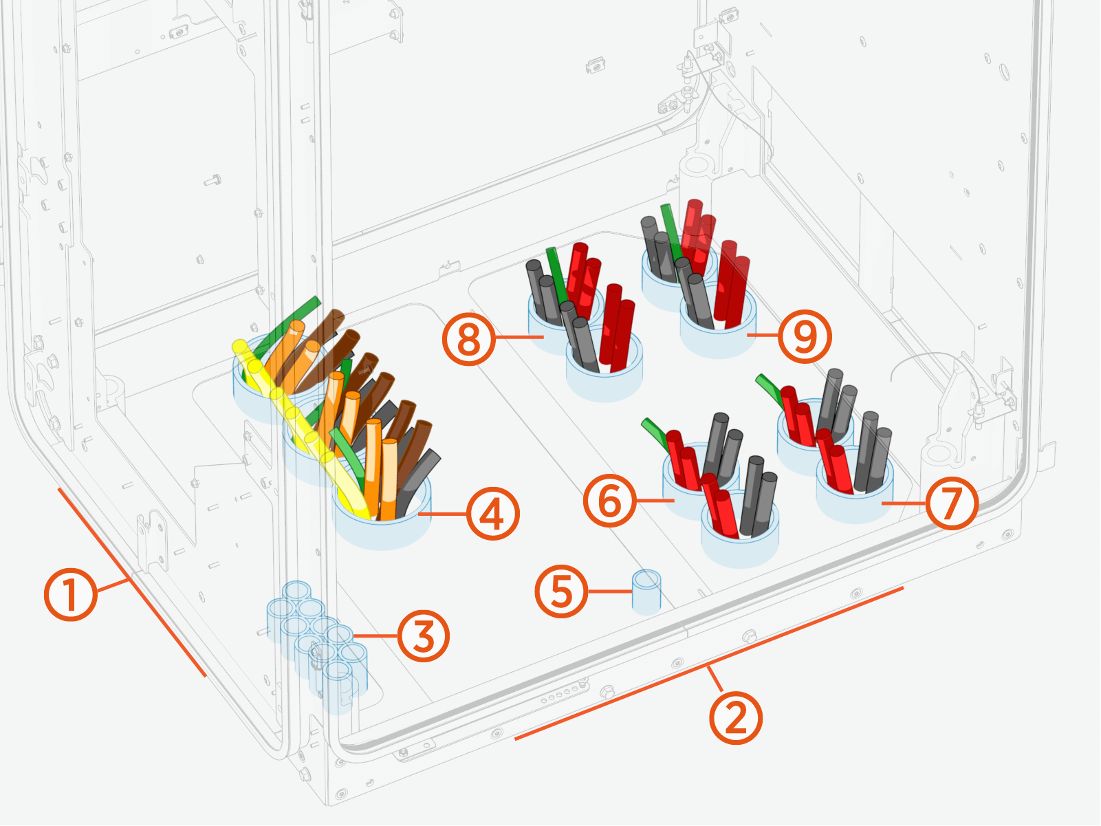
(1) Cabinet front side
(2) Cabinet intake (right) side
(3) 48 V DC, Ethernet, Safety Hub, and door interlock
(4) AC input
(5) Shunt trip
(6) DC BUS (intake side)
(7) EXT B
(8) DC BUS (exhaust side)
(9) EXT D
IMPORTANT: The following table provides the maximum size and quantity of conduits that can be installed on Express Solo configured for standard wire entry. The actual conduit size and quantity must be chosen based on site specific wiring requirements.
|
Conduits For |
Conduit Quantity x Trade Size |
|---|---|
|
AC input |
3 x 4 inch max. or 4 x 2.5 inch max. |
|
DC BUS:
|
1 x 4 inch max. per side or 2 x 3 inch max. per side |
|
External DC output:
|
1 x 4 inch max. per output or 2 x 3 inch max. per output |
|
48 V DC, Ethernet, and Safety Hub (*) |
1 x 1 inch to each Power Link 1 inch size conduit is required. The quantity of conduits will depend on the configuration. |
|
Ethernet and door interlock (**) |
1 x 1 inch |
|
Optional Features (Soft shutdown switch, shunt trip, hardwire Ethernet) |
3 x 4 inch max. |
(*) 48 V DC, Ethernet, and Safety Hub wires travel in the same conduit when connecting Express Solo to a Power Link. Safety Hub wires are required only for certain models of Power Link. Refer to the installation guide of the Power Link model specific to your project to determine if Safety Hub twisted wire connection is required. (**) Ethernet and door interlock sensor wires travel in the same conduit when pairing an Express Solo to another Express Solo.
Wire Terminal and Bus Bar Locations
The following identifies the wire terminals and bus bars accessible from the intake side (right side) of Express Solo. (Safety shields are hidden from view.)

|
Ref |
Part |
|---|---|
| (1) |
Safety Hub ports |
| (2) |
Ethernet ports |
| (3) |
DC terminal block for 48 V DC, soft shutdown switch, door interlock sensor wires |
| (4) |
Shunt trip terminals |
| (5) |
DC BUS (intake side) bus bars |
| (6) |
EXT B bus bars |
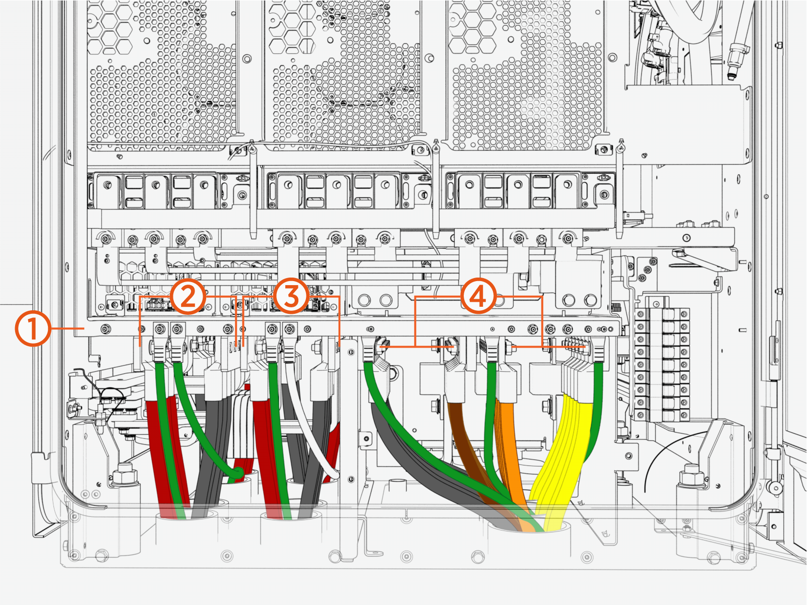
The following identifies the wire terminals and bus bars accessible from the exhaust side (left side) of Express Solo. (Safety shields are hidden from view.)
|
Ref |
Part |
|---|---|
| (1) |
Ground/PE bar (with wire landing studs) |
| (2) |
EXT D bus bars |
| (3) |
DC BUS (exhaust side) bus bars |
| (4) |
AC input (L1, L2, L3) and neutral bus bars |
Wire Specifications
All requirements and specifications given below are critical for proper conductor selection and must be followed for all installations.
The requirements and specifications in this section reflect what is supported by Express Solo. When Express Solo is connected to another ChargePoint product, such as a Power Link charging dispenser, conductor material, insulation rating, wire gauge, quantity, lugs, and other wiring characteristics may be further constrained by the connected product. Refer to the site design guide for each connected product and follow the most restrictive requirements.
Electrical Characteristics
The following table summarizes circuit current, voltage, conductor rating, and configuration for each circuit to support proper conductor selection.
|
Circuit |
Maximum Current |
Circuit Voltage / Conductor Rating |
Number of Poles |
|---|---|---|---|
|
AC input |
Refer to AC Continuous Input Current table |
480 V AC (US); 600 V AC (Canada); 600 V rated conductors |
3 + PE |
|
DC BUS (power sharing) |
750 A |
1000 V rated conductors |
2 + PE |
|
External DC output |
Depends on Power Link model and configuration |
1000 V rated conductors |
2 + PE |
|
48 V DC output |
32 A |
48 V DC; 300 V rated conductors |
2 |
|
Shunt trip, Safety Hub, and door interlock |
- | Same conductor insulation rating as AC input |
2 (twisted pair) |
Conductor Material and Temperature Rating
The following requirements apply to conductor material and temperature ratings:
-
For AC input and external DC output (EXT B, EXT D) and DC BUS conductors, use copper or aluminum conductors rated for 90 °C (194 °F).
-
For 48 V DC, shunt trip, Safety Hub, and door interlock conductors, use copper conductors only.
Insulation Requirements
Select conductor insulation types based on these requirements:
-
For AC input conductors, use THHN
Thermoplastic High Heat-Resistant Nylon-Coated / THHW Thermoplastic High Heat-Tesistant, Water-Resistant / THW Thermoplastic Heat-Resistant, Water-Resistant‑2 / THWN‑2, based on site conditions (e.g., dry, damp, or wet locations). -
For external DC output and DC BUS conductors, use XHHW / XHHW‑2, based on site conditions (e.g., dry, damp, or wet locations).
-
For 48 V DC conductors, use insulation suitable for the installation environment (e.g., dry, damp, or wet locations).
-
For shunt trip, Safety Hub, and door interlock conductors, due to routing proximity to power conductors, use insulation with the same voltage rating as the AC input conductors.
Neutral Configuration
Express Solo is available in two factory configurations: with a Neutral landing or without one. A Neutral connection is not required for standard charging applications. However, some Vehicle‑to‑Grid (V2G) systems rely on phase‑to‑neutral voltage measurements for control functions. When planning a V2G deployment, contact ChargePoint to ensure the correct Express Solo configuration is selected.
Lugs and Terminations
Plan for lugs and terminations using the following requirements:
-
Use copper lugs for copper conductors and aluminum lugs for aluminum conductors. The lugs must be nickel-, tin-, or silver-plated compression lugs (not mechanical lugs). Nickel-plated lugs installed with dielectric grease are recommended.
-
When using aluminum lugs, ChargePoint recommends applying an appropriate antioxidant compound to aluminum conductors when terminating into tin-, nickel-, or silver-plated lugs, where required by code or specified by the lug manufacturer.
Field Verification
After pulling conductors through conduit, all AC input, external DC output, and DC BUS conductors must undergo insulation resistance testing to verify that insulation has not been damaged during the pull.
Wire Quantity, Size, and Termination
IMPORTANT: Following are wire specifications for Express Solo, including the maximum quantity and size that the wire terminals can accommodate. All sizing assumes a maximum ambient temperature of 50 °C (122 °F). Where the maximum wire size is listed, the actual wire quantity and size must be chosen based on site-specific wiring requirements and in accordance with the maximum allowed conduit filling rate per local code.
|
Wire |
Quantity |
Size |
Termination |
|---|---|---|---|
|
AC input |
Max. 18 wires (six per phase) |
Max. 300 MCM |
Lug: Compression lug; short barrel and tongue with single hole sized for M12 (0.5 in) stud Max. tongue width: 36 mm (1.3 in). |
|
AC ground |
Max. 3 wires (1 per AC conduit) |
Refer to local code for size |
Lug: Short barrel and tongue with single hole sized for M6 (0.25 in) stud |
|
DC BUS: DC BUS (intake side) DC BUS (exhaust side) |
Max. 8 wires per side (four per pole) |
Max. 300 MCM (*) |
Lug: Compression lug; short barrel and tongue with single hole sized for M12 (0.5 in) stud. Max. tongue width: 36 mm (1.3 in). |
|
External DC outputs: EXT B EXT D |
Max. 8 wires per output (four per pole) |
Max. 300 MCM (*) |
Lug: Compression lug; short barrel and tongue with single hole sized for M12 (0.5 in) stud. Max. tongue width: 36 mm (1.3 in). |
|
DC grounding |
Max. 2 wires per interface (1 per interface conduit) |
Refer to local code for size |
Lug: Short barrel and tongue with single hole sized for M6 (0.25 in) stud. |
|
48 V DC output |
Max. 4 wires per connected Power Link (2 wire pairs; each pair has one wire per pole) |
Stripped wire end or ferrule |
|
|
Ethernet |
Max. 3 cables 1 per Power Link 1 for hardwire Ethernet (if needed) |
Outdoor-rated Cat6 STP |
RJ45 connector, shielded |
|
Door interlock sensor |
2 wires |
Stripped wire end or ferrule |
|
|
Safety Hub |
2 wires per connected Power Link (***) |
Stripped wire end |
|
|
Soft shutdown switch |
2 wires |
Stripped wire end or ferrule |
|
|
Shunt trip |
2 wires |
Stripped wire end or ferrule |
(*) If Aluminum AA8000 conductors are used, max. 400 MCM can be accommodated. (**) The required Ethernet cable type depends upon the cable run length. See Ethernet Requirements. (***) Safety Hub is not required for all models of Power Link. Refer to the installation guide of the Power Link model specific to your project to determine if Safety Hub twisted wire connection is required.
For AC input, Express Solo allows a maximum of 18 total current carrying conductors. If utilizing this wiring configuration, install spreader bars at the breaker or transformer to split the outputs across the high number of conductors.