Civil and Mechanical Design
This section provides civil and mechanical site design information for Power Link 2000.
Weights
| Component | Weight |
|---|---|
|
Power Link 2000 - overhead-mount (excludes charging cables and CMK |
120 kg |
|
Power Link 2000 - pedestal-mount with LCC (excludes charging cables and CMK |
200 kg |
|
Power Link 2000 - pedestal-mount with non-LCC (excludes charging cables and CMK |
180 kg (400 lbs) |
|
Charging cable |
16 - 37 kg |
|
Standard CMK |
20 kg (44 lbs) |
|
Tall CMK |
38.5 kg (85 lbs) |
|
Overhead CMK |
10 kg (22 lbs) |
|
Packaging excluded from weights listed above |
45 - 90 kg |
Dimensions
This section provides the dimensions of the Power Link 2000 in various configurations.
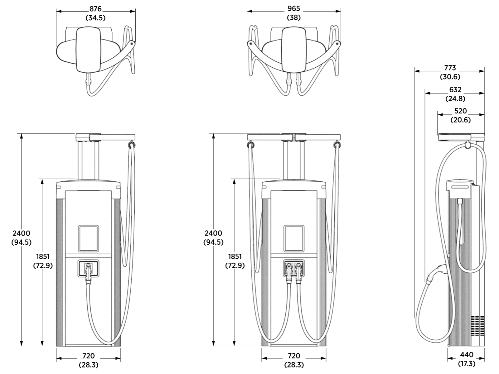
Pedestal-Mount Power Link 2000 With LCC, Single or Dual Cable, and Standard CMK
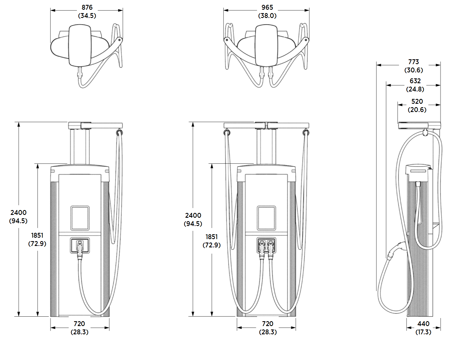
Pedestal-Mount Power Link 2000 With Non-LCC, Single or Dual Cable, and Standard CMK
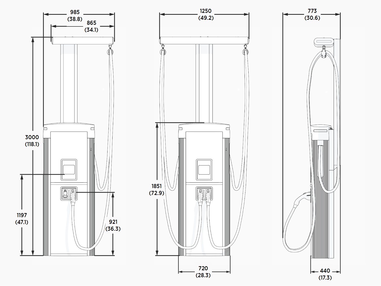
Pedestal-Mount Power Link 2000 With Non-LCC, Single or Dual Cable, and Tall CMK
Pedestal-Mount Power Link 2000 With Non-LCC, Single or Dual Cable, and Overhead CMK
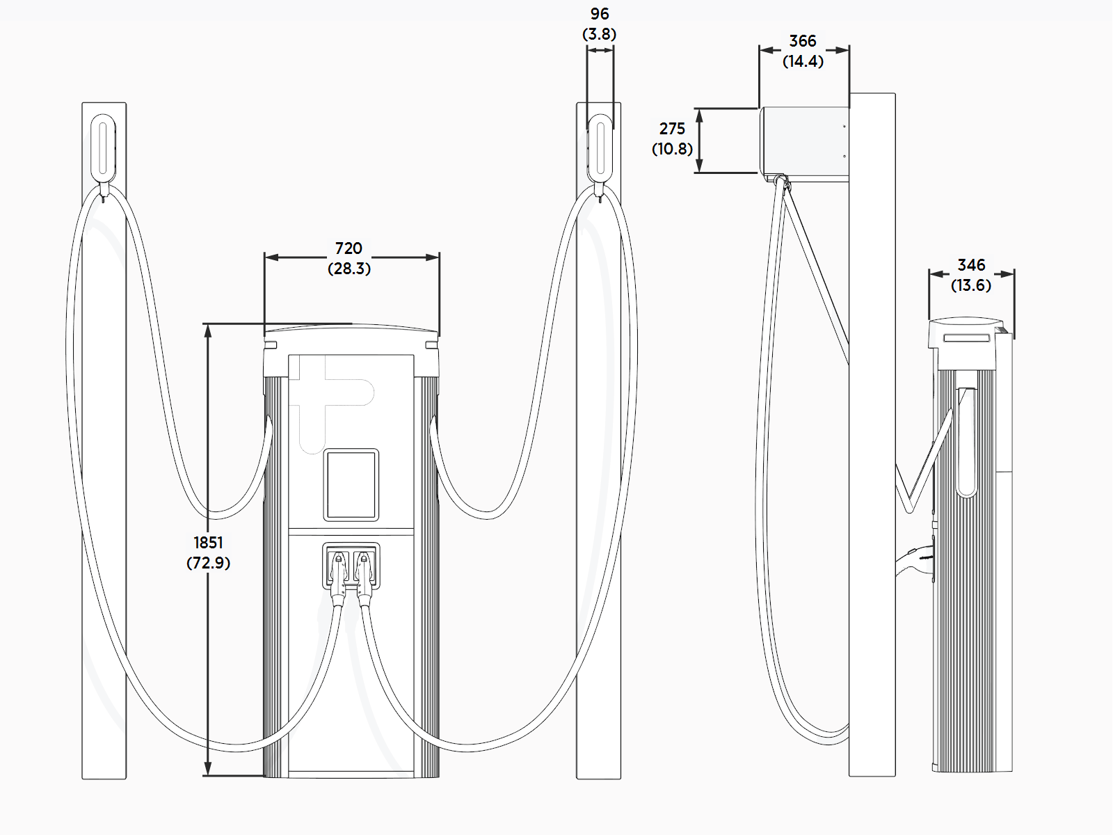
The customer must provide the poles at the site for installing pedestal-mount (single or dual cable) Power Link 2000 enclosures with overhead CMK Cable Management Kit and tether ball extension. These are not provided by ChargePoint.
Overhead-Mount Power Link 2000 With Single or Dual Cable and Overhead CMK
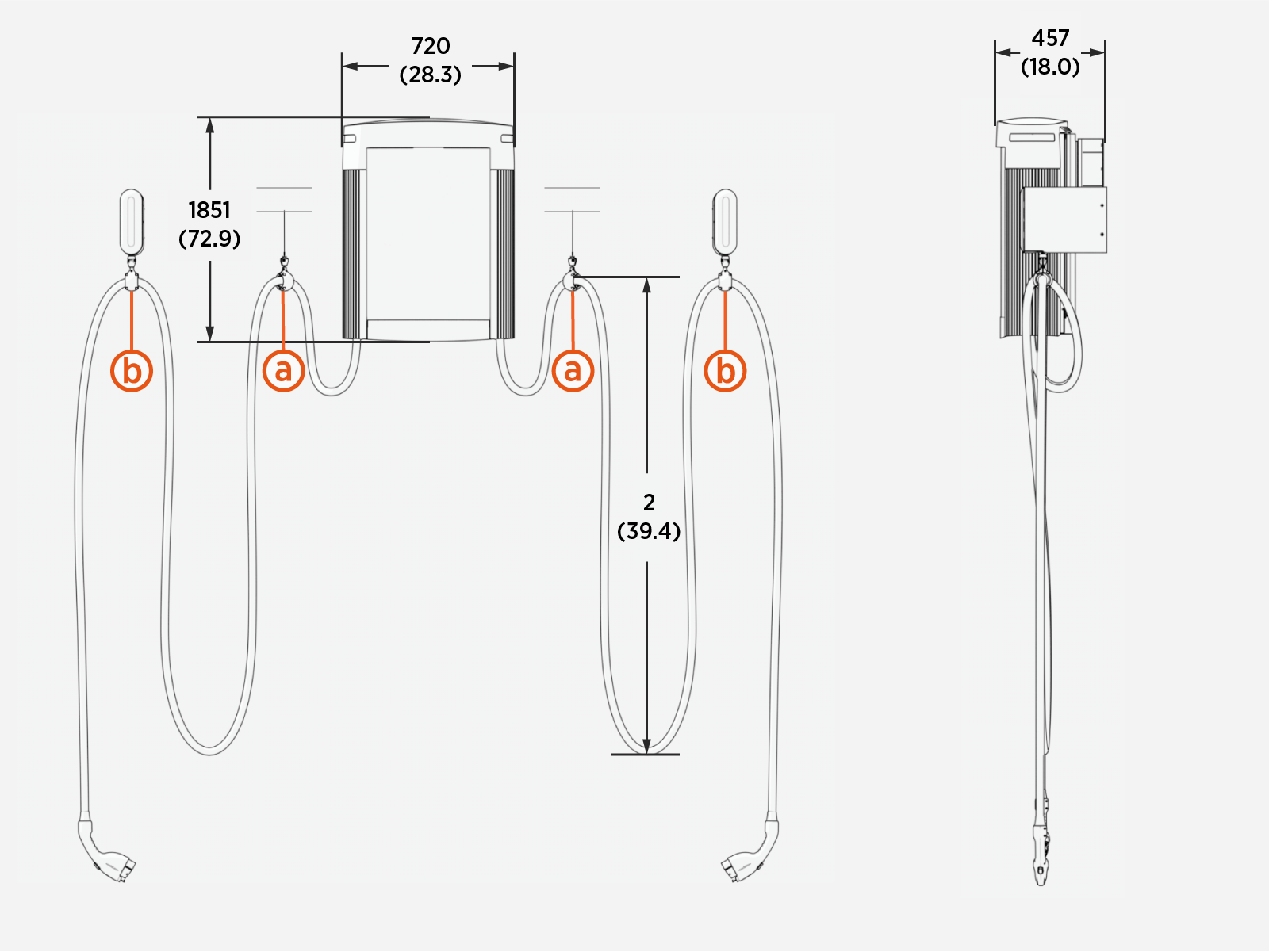
The CMK Cable Management Kit might not fully retract certain charging cables due to their heavier weight. Adding a tether point and a tether hook kit reduces cable weight on the CMK Cable Management Kit, allowing the cable to retract fully.
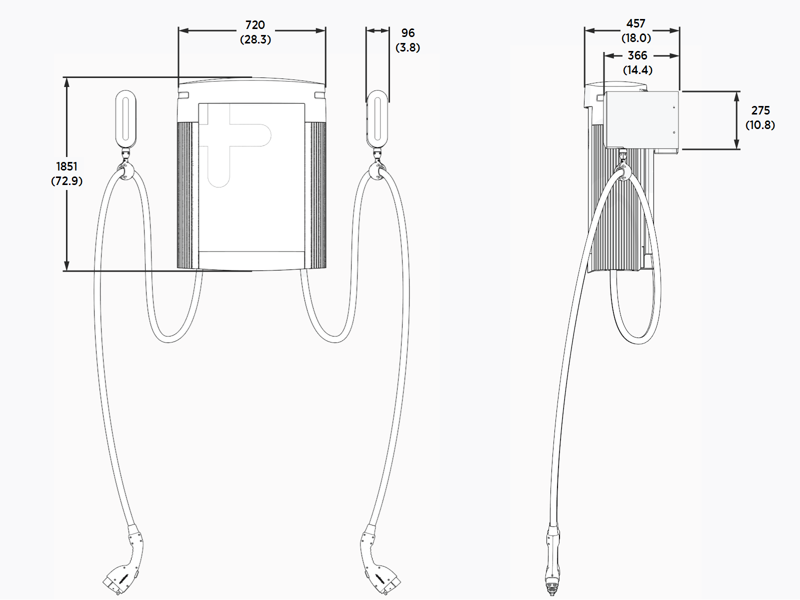
Overhead-Mount Power Link 2000 With Tether Hook
Use tether hooks as additional support for overhead CMKs or to enable the use of third party hoist or cable management solutions.
The tether hook (a) can be attached to either a fixed point or to an alternate cable management mechanism (b) such as a winch.
In the following image, the charge cable is held with a fixed tether hook (a) and a tool balancer (b). Adjust the tether hook or tool balancer location as necessary for site requirements.
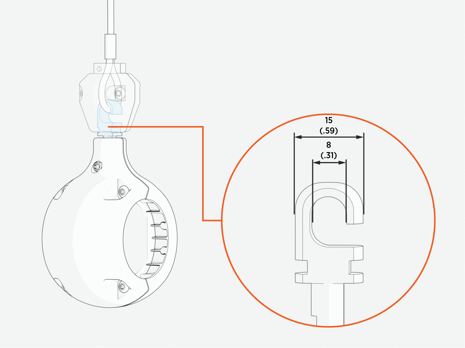
Tether hook dimensions are given in the following image.
Power Link 2000 Pedestal Mounting Specifications
The pedestal-mount Power Link 2000 must be installed on either a newly poured concrete pad embedded with the Concrete Mounting Template (CMT) or on an existing concrete surface using the Surface Conduit Entry (SCE Surface Conduit Entry) kit.
Another option available through a third party is precast concrete blocks. For more details, contact ChargePoint.
Surface Conduit Entry) kit, which includes the hardware needed to install on an existing concrete surface.Concrete Pad Specifications
The pedestal-mount Power Link 2000 must be installed on a concrete pad or engineered foundation. The concrete pad may be either newly poured or an existing concrete surface, provided it meets the requirements below.
Surface requirements
The concrete surface must be smooth and may not exceed a slope of 10 mm per meter (0.12 in per ft).
If an existing surface does not meet this requirement, a localized leveling pad must be poured to achieve the required slope tolerance.
Adhering to the slope requirement is critical for cabinet stability, proper alignment, and long-term structural performance.
New concrete pad requirements
A new concrete pad may be:
-
Site‑specific, designed by a licensed structural engineer, or
-
Selected from the standard pad specifications provided in this section.
Conservative stability specifications for the Power Link 2000 are listed in the table below for the following design scenarios:
-
170 mph wind, high seismic, Class 3 Soil
-
170 mph wind, high seismic, Class 4 Soil
-
170 mph wind, high seismic, Class 5 Soil
-
140 mph wind, lower seismic, Class 3 Soil
-
140 mph wind, lower seismic, Class 4 Soil
-
140 mph wind, lower seismic, Class 5 Soil
All scenarios assume:
-
Minimum concrete rating of 2500 PSI.
-
All-threaded M16 anchor bolts are embedded 229 mm (9 in) into the concrete pad and are made of ASTM F1554 Grade 55 carbon steel and hot dip galvanized (HDG
Hot Dipped Galvanized). -
The anchor bolts placement is centered within the designed stability area.
|
Design Scenarios |
Pad Width |
Pad |
#N1 @ S1” O.C. Top Rebar |
#N2 @ S2” O.C. Bottom Rebar |
|
|---|---|---|---|---|---|
|
1 |
1499 mm (59 in) |
1499 mm (59 in) |
432 mm (17 in) |
#4 @ 305 mm (12 in) O.C. |
#4 @ 305 mm (12 in) O.C. |
|
2 |
1499 mm (59 in) |
1499 mm (59 in) |
610 mm (24 in) |
#5 @ 305 mm (12 in) O.C. |
#5 @305 mm (12 in) O.C. |
|
3 |
1499 mm (59 in) |
1499 mm (59 in) |
610 mm (24 in) |
#5 @ 305 mm (12 in) O.C. |
#5 @ 305 mm (12 in) O.C. |
|
4 |
1219 mm (48 in) |
1219 mm (48 in) |
330 mm (13 in) |
#4 @ 305 mm (12 in) O.C. |
#4 @ 305 mm (12 in) O.C. |
|
5 |
1219 mm (48 in) |
1219 mm (48 in) |
483 mm (19 in) |
#5 @ 305 mm (12 in) O.C. |
#5 @ 305 mm (12 in) O.C. |
|
6 |
1219 mm (48 in) |
1219 mm (48 in) |
483 mm (19 in) |
#5 @ 305 mm (12 in) O.C. |
#5 @ 305 mm (12 in) O.C. |
In extreme environmental conditions, a larger pad may be required. Conversely, sites with less stringent wind, seismic, or soil conditions may allow for a smaller pad, subject to engineering approval.
Existing pad requirements
An existing concrete pad may be used if it meets one of the conservative stability specifications listed above, or if it is evaluated and approved by a structural engineer using the parameters below.
|
Parameter |
Value |
|---|---|
|
Weight |
See Weights |
|
Height x width |
See Dimensions |
|
Frontal area |
Height * width |
|
CG height |
1524 mm (60 in) |
|
Anchor bolts size and quantity |
M16 (x4) |
|
Anchor bolts embedment |
229 mm (9 in) |
|
Anchor bolts placement |
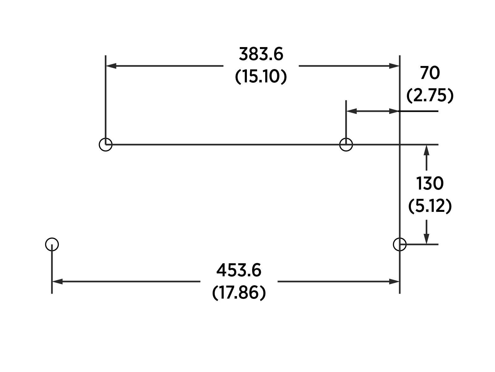
Anchor Bolts Placement
The Power Link 2000 pedestal mounts over four anchor bolts embedded in the concrete pad. The anchor bolt pattern is given below.
Standard Mount with Concrete Mount Template
The most common mounting method for the pedestal-mount Power Link 2000 is new pad installation using a Concrete Mounting Template (CMT) with conduit stub-up wire entry.
-
The Power Link 2000 pedestal mounts onto four M16 anchor bolts exposed 76 mm (3 in) above the concrete pad.
-
The CMT is embedded in a newly poured concrete pad to align anchor bolts and underground run stub-up wiring conduits or armored cables.
The Power Link 2000 CMT positions the anchor bolts and conduits stub-ups as shown below.
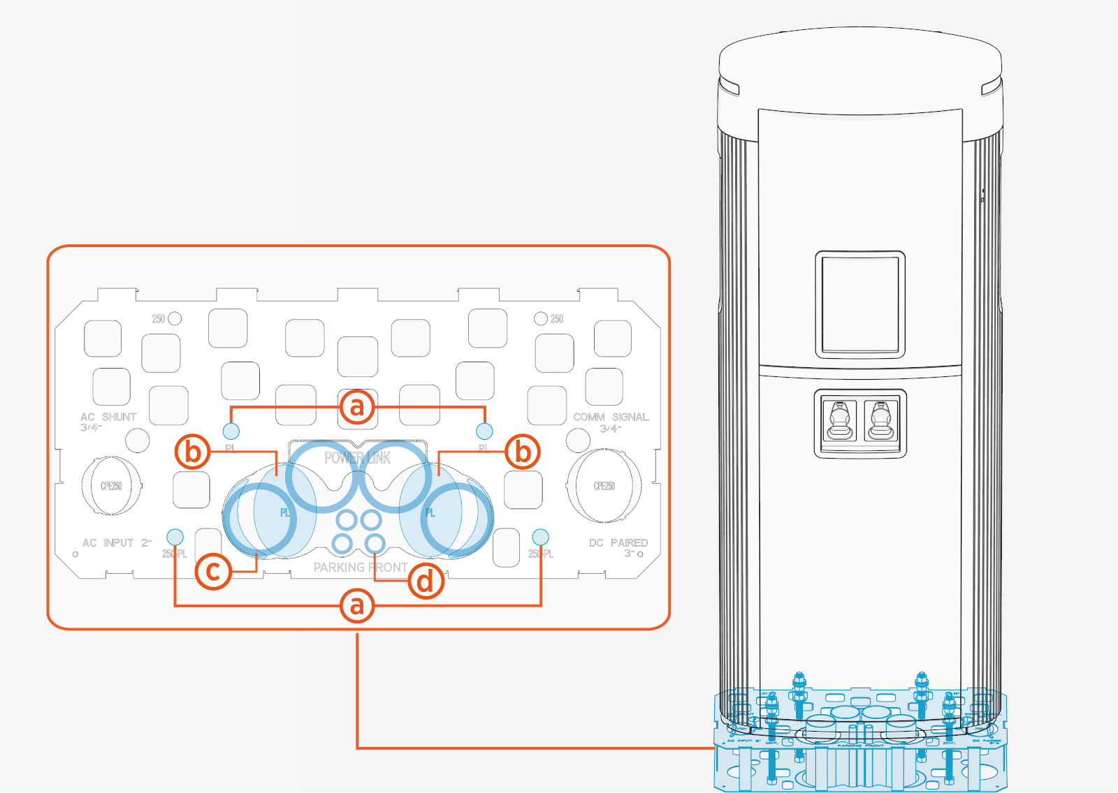
-
M16 anchor bolt (x4) locations (see Anchor Bolts Placement).
-
Breakaway tabs for conduits or armored cables.
-
Conduits for DC power path input wires (sample conduit configuration shown).
-
Conduits for 48 V DC and Ethernet wires (sample conduit configuration shown).
In regions that do not use conduits and/or use armored cables, the cables may be laid per the conduit layout defined by the CMT.
The Power Link 2000 CMT is shipped separately and must be assembled onsite before pouring the concrete pad. The CMT must be embedded with its top panel positioned 51 mm (2 in) below the concrete surface. Refer to the Concrete Mounting Template Guide for further details.
For standard mount conduit quantity and size requirements, refer to Conduit Requirements.
Surface Mount
The pedestal-mount Power Link 2000 may be installed on an existing concrete surface in accordance with the following guidelines:
-
The concrete surface must be inspected and approved by a structural engineer as described in Concrete Pad Specifications.
-
The anchor bolts must be installed in the concrete surface as follows:
-
Anchor holes are drilled into the concrete using the anchor bolt pattern given in Anchor Bolts Placement. The holes are drilled to a depth so that 76 mm (3 in) of each anchor bolt remains exposed above the concrete pad.
-
Anchor bolts are epoxied into the holes. Use an epoxy with a minimum bonding strength of 11.7 MPa, compressive strength of 82.7 MPa minimum, and tensile strength of 49.3 MPa minimum. For example, Hilti HIT-RE 500 V3 (normal cure) or Hilti HIT-HY 200-A (fast cure).
Different epoxy types have different cure times at various temperatures. Check local temperatures for the site in advance to help choose an appropriate epoxy.
-
-
Use the provided hot-dip galvanized M16 anchor bolts.
-
Wires must enter the enclosures using Surface Wire Entry.
Surface Wire Entry
The pedestal-mount Power Link 2000 support wiring that is run above ground in protected wireways for locations where no underground wiring access exists (parking garages, etc.) or where underground junction boxes are not permitted.
If wires or cables are run above ground:
-
They must be housed in wireways that conform to local code.
-
Ensure the plans for the concrete pad and access area allow full service access to all components. Surface wires entry might require larger clearance areas than embedded installations. A minimum of 610 mm (2 ft) clearance at rear side is required.
-
Use flexible wires and conduits, or armored cables.
-
Use LB conduit bodies to route wires into Power Link 2000 from rear left or rear right, and they must fit within the rear clearance of 610 mm or 2 ft.
-
Use suitable conduit fittings to secure and seal the conduits and/or conduit bodies.
-
Prepare the concrete surface where the components will be anchored so that the concrete surface is solid, smooth, and level with no old hardware or stub-ups extending above ground.
Surface wires must enter the pedestal-mount Power Link 2000 using a Surface Conduit Entry (SCE Surface Conduit Entry) Kit. The SCE Surface Conduit Entry Kit offers the following benefits:
-
Support of the weight of conduits or armored cables without compromising cover panel integrity
-
Ensure all terminations meet ingress requirements where they meet the component
-
Ensure no obstructions to ventilation, which is required during operation
The SCE Surface Conduit Entry Kit provides a sturdy pedestal cover panel onto which surface conduits or armored cables may be fastened at the rear side of the Power Link 2000.
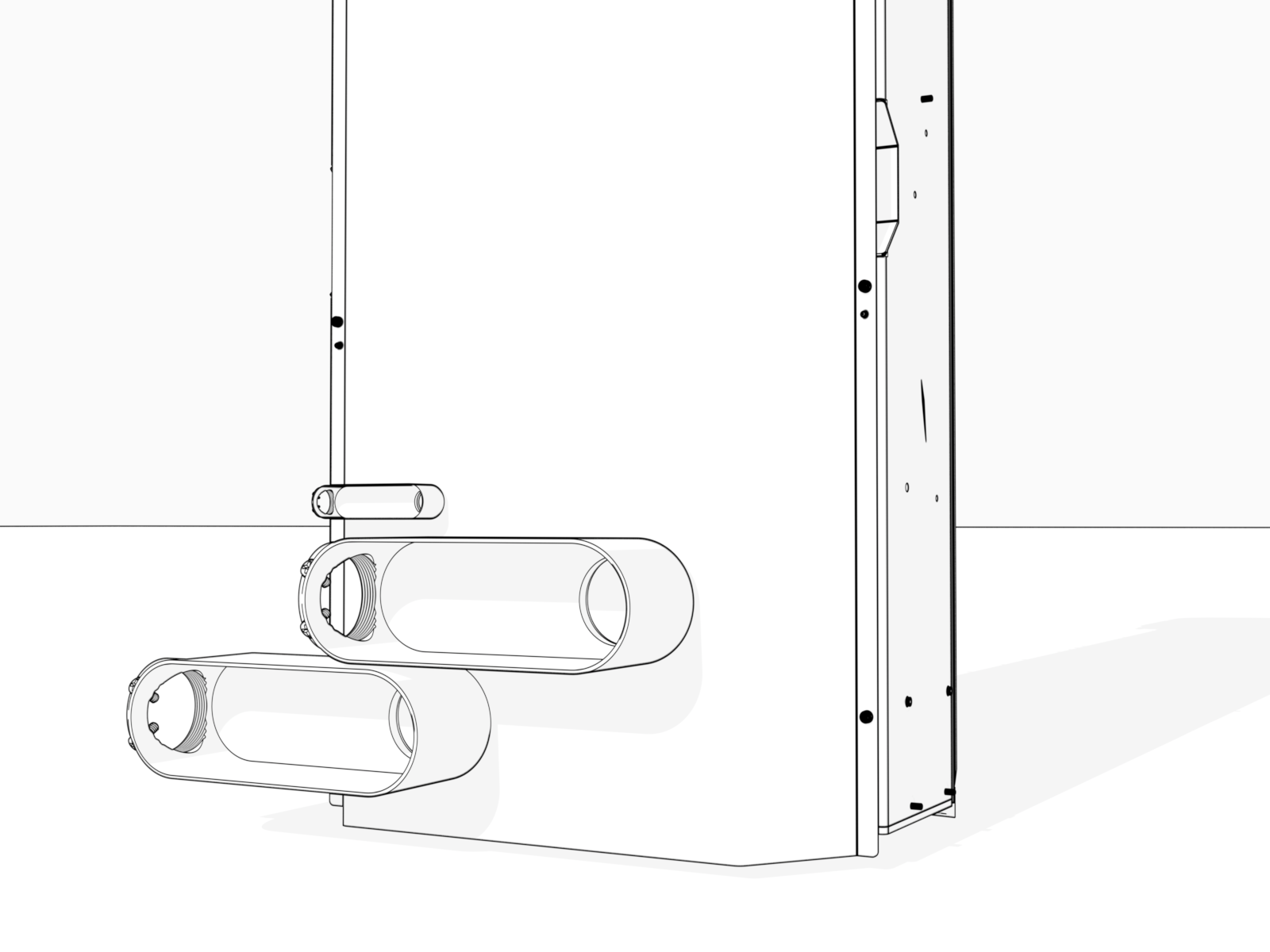
For further information on the SCE Surface Conduit Entry Kit, refer to the Power Link 2000 Installation Guide. For conduit quantity and size requirements when utilizing the SCE Surface Conduit Entry Kit, refer to Conduit Requirements.
The SCE Surface Conduit Entry kit is used for surface wire entry for only the pedestal-mount Power Link 2000. It can not be used with a overhead-mount Power Link 2000.
Cable Management Kit Mount Specifications
Standard and Tall CMK
For pedestal-mount Power Link 2000, the standard and tall CMKs mount to the back of Power Link 2000. Refer to Dimensions for overall mounting dimensions of Power Link 2000 with standard or tall CMK Cable Management Kit. The standard CMK Cable Management Kit can be adjusted to a lower height for parking garages. Refer to the Express Distro Power Link 2000 Installation Guide for details.
Overhead CMK
If you want to use an overhead CMK Cable Management Kit with a pedestal-mount Power Link 2000, you must install a pole to mount the overhead CMK Cable Management Kit next to the Power Link 2000 charging cables.
To mount the overhead CMK Cable Management Kit for a pedestal-mount Power Link 2000:
-
You must design and/or purchase the pole. ChargePoint does not sell and/or supply the pole.
-
The pole must have a structural capacity of 1780 N (400 lbf), and it must be designed or verified by a structural engineer per local codes. In the event of a vehicle driveaway incident, this structural strength is required to withstand the pull-out force of the vehicle.
-
Unless the pole needs to be at a certain location for a specific vehicle inlet, the overhead CMK
Cable Management Kit when mounted onto the pole must have an optimum height of 3 m (10 ft) for maximum cable reach, come at the center of the parking space, and be as far forward as possible aligned with the front of the bollards (see Bollards for the bollards placement and Dimensions for the overhead CMK Cable Management Kit's depth).Images are not to scale. Measurements appear in metric units (m) followed by imperial equivalents (ft).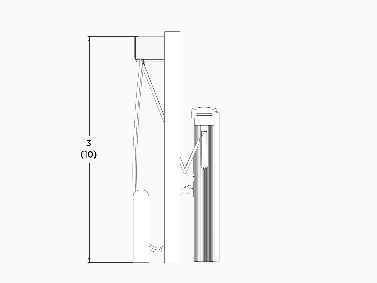
-
The overhead CMK
Cable Management Kit must be mounted using its bracket (supplied by ChargePoint) that attaches to its back. The bracket has four holes sized for M8 bolts to mount the overhead CMK Cable Management Kit onto the pole.The installer must provide the M8 bolts. These are not provided by ChargePoint.
Images are not to scale. Measurements appear in metric units (mm) followed by imperial equivalents (inches).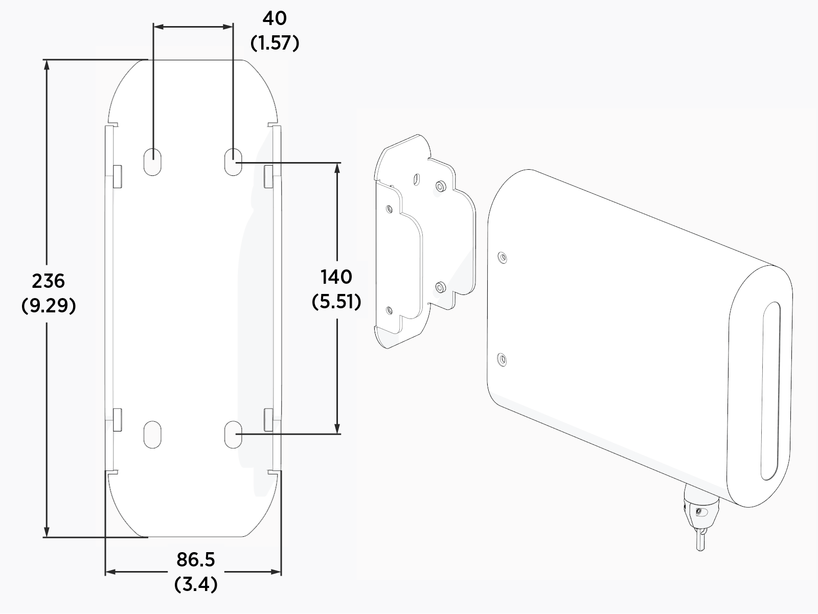
Power Link 2000 Overhead Mounting Specifications
The overhead-mount Power Link 2000 mounts onto a wall or an overhead structure (such as a gantry) using a bracket that attaches to its back. The bracket has six mounting holes sized for M8 bolts.


For overhead-mount stations:
-
The Power Link 2000 must be mounted upright. Do not mount it in any other orientation.
-
The wall must be smooth and plumb.
-
The wall or overhead structure must have a structural capacity of 1780 N (400 lbf) in addition to the Power Link 2000 weight. The structure must also be designed or verified by a structural engineer per local codes. In the event of a vehicle drive away incident, this structural strength is required to withstand the pull-out force of the vehicle.
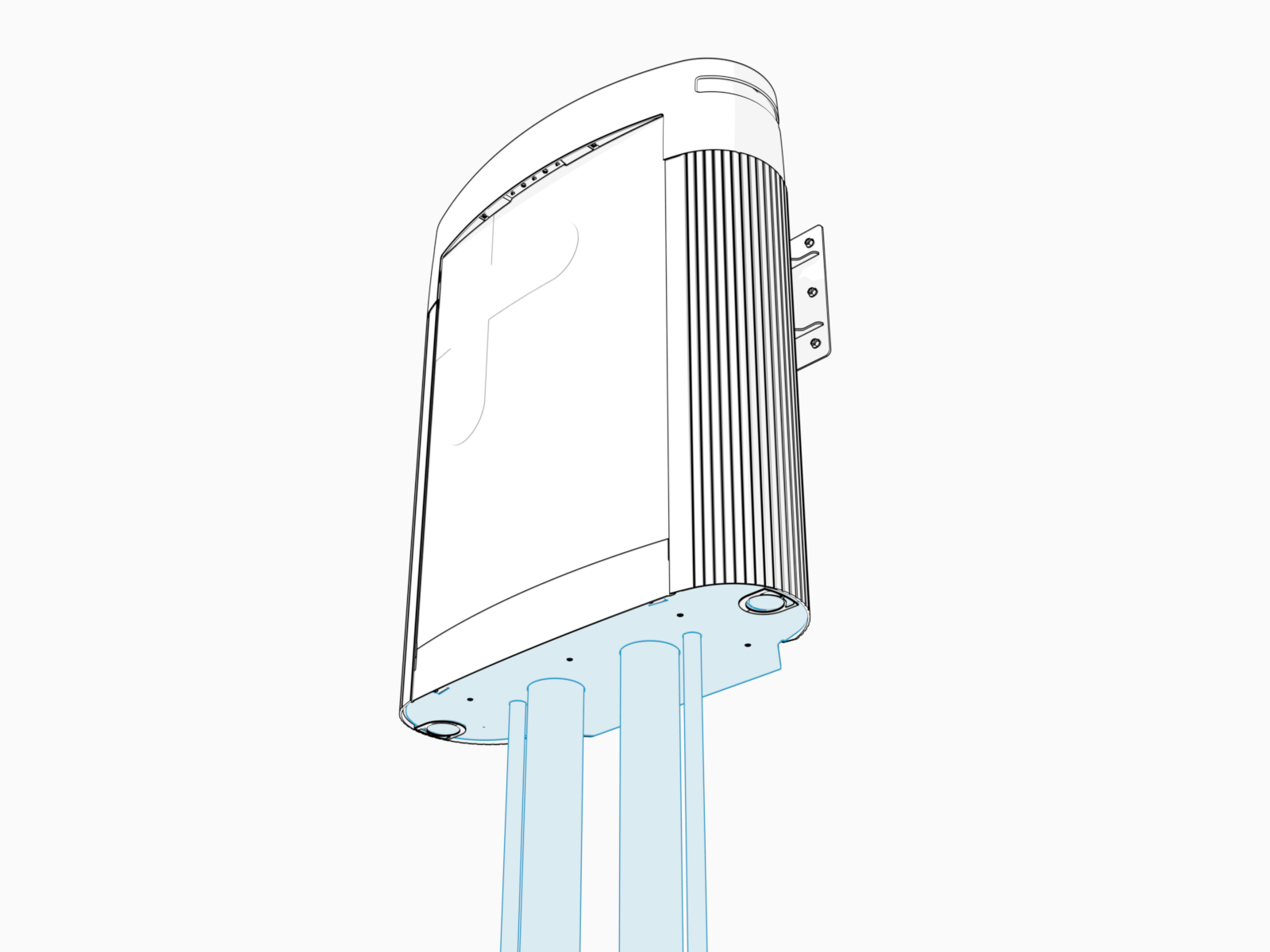
Wires and cables enter overhead-mount Power Link 2000 through its bottom gland plate by conduit or as armored cable. The DC power path input conduits should attach to the gland plate at locations that align the wires to their intended power path landings. See Wire Terminal and Bus Bar Locations
For surface run wiring to the overhead-mount Power Link 2000:
-
All wires must be housed in wireways that conform to local code.
-
Use flexible wires.
-
Use suitable conduit fittings to secure and seal the conduits to the enclosure.
For overhead-mount conduit quantity and size requirements, refer to Conduit Requirements.
Mounting height specifications and guidelines are given below:
The height for overhead mount must be calculated based on site specific requirements. For assistance, contact ChargePoint.
-
For maximum cable reach :
-
Mount the Power Link 2000 at a height of 6096 mm (240 in) above the finished floor.
-
Mount the overhead CMK
Cable Management Kit bracket in-line and 203 mm (8 in) away from the Power Link 2000 bracket.
The mounting height can be adjusted based on site needs.
Images are not to scale. Measurements appear in metric units (mm) followed by imperial equivalents (inches).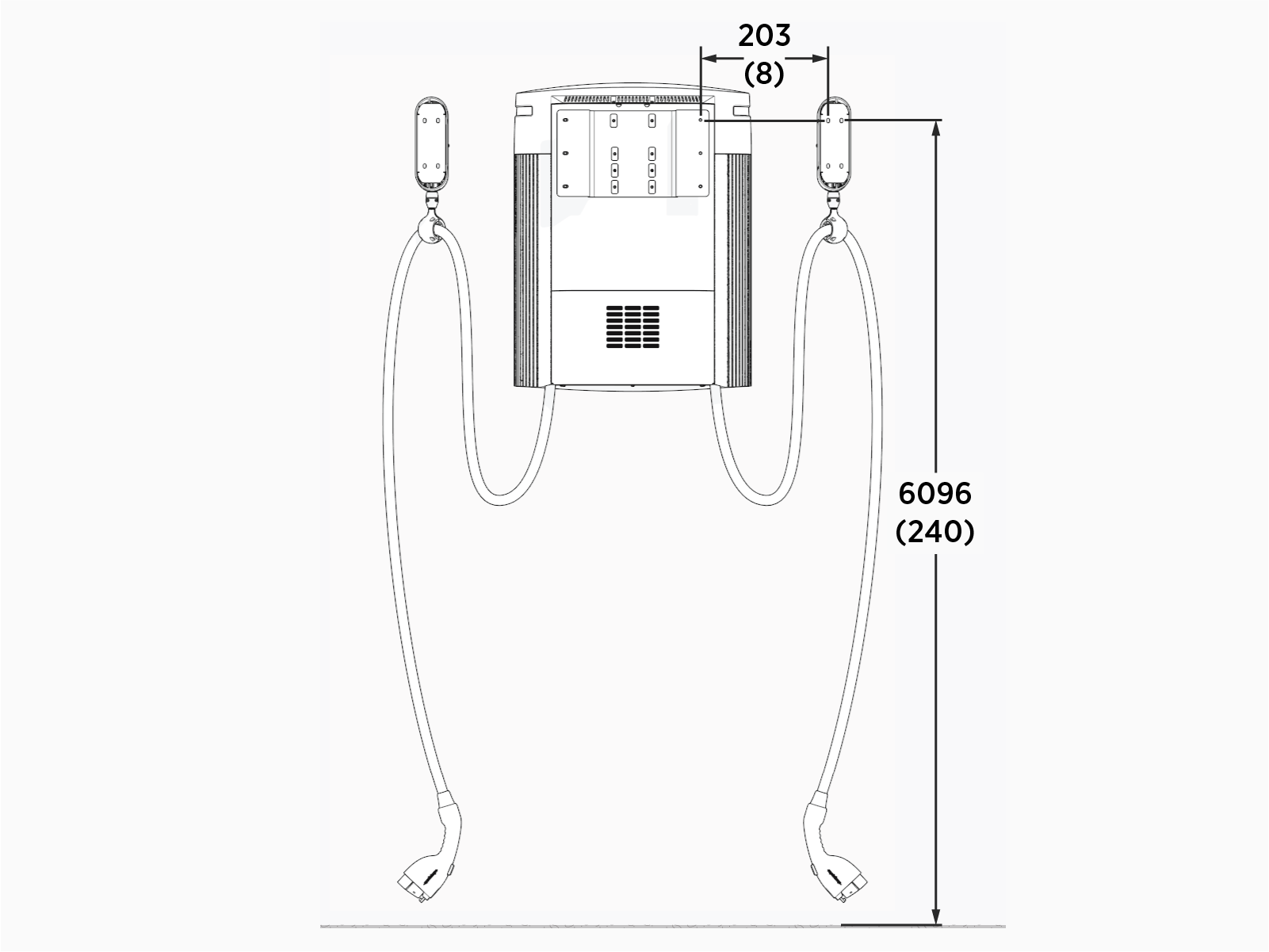
-
-
The overhead CMK
Cable Management Kit bracket must be mounted a minimum of 203 mm (8 in) away from the outer sides of the Power Link 2000 mounting bracket.
-
The overhead CMK
Cable Management Kit cable measures 3 m (118 in) when fully extended.Images are not to scale. Measurements appear in metric units (m) followed by imperial equivalents (inches).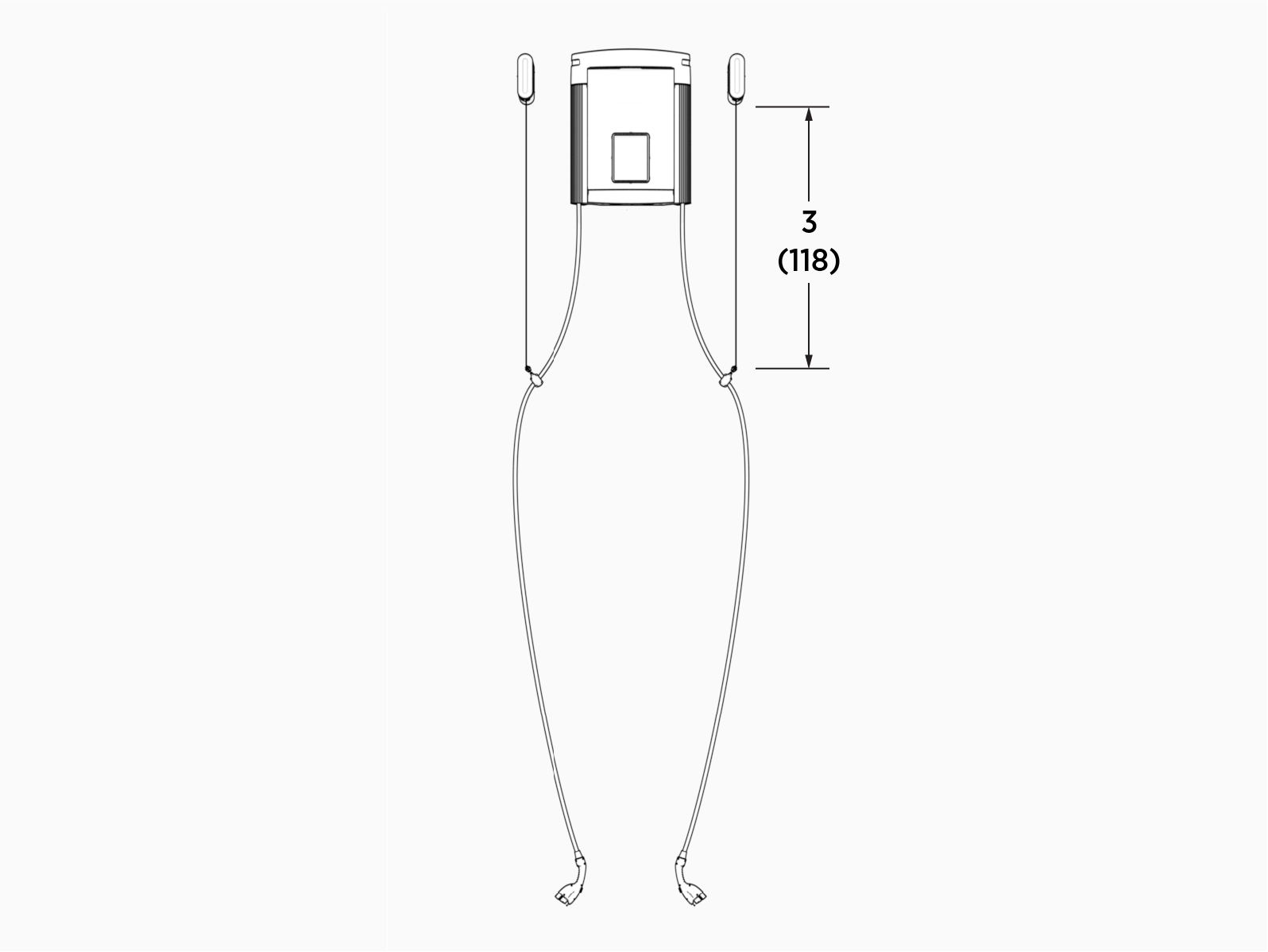
Drainage
Ensure any site slopes, walls, or fencing do not trap water around the installation site.
Clearances
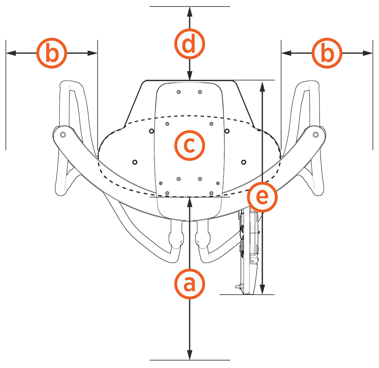
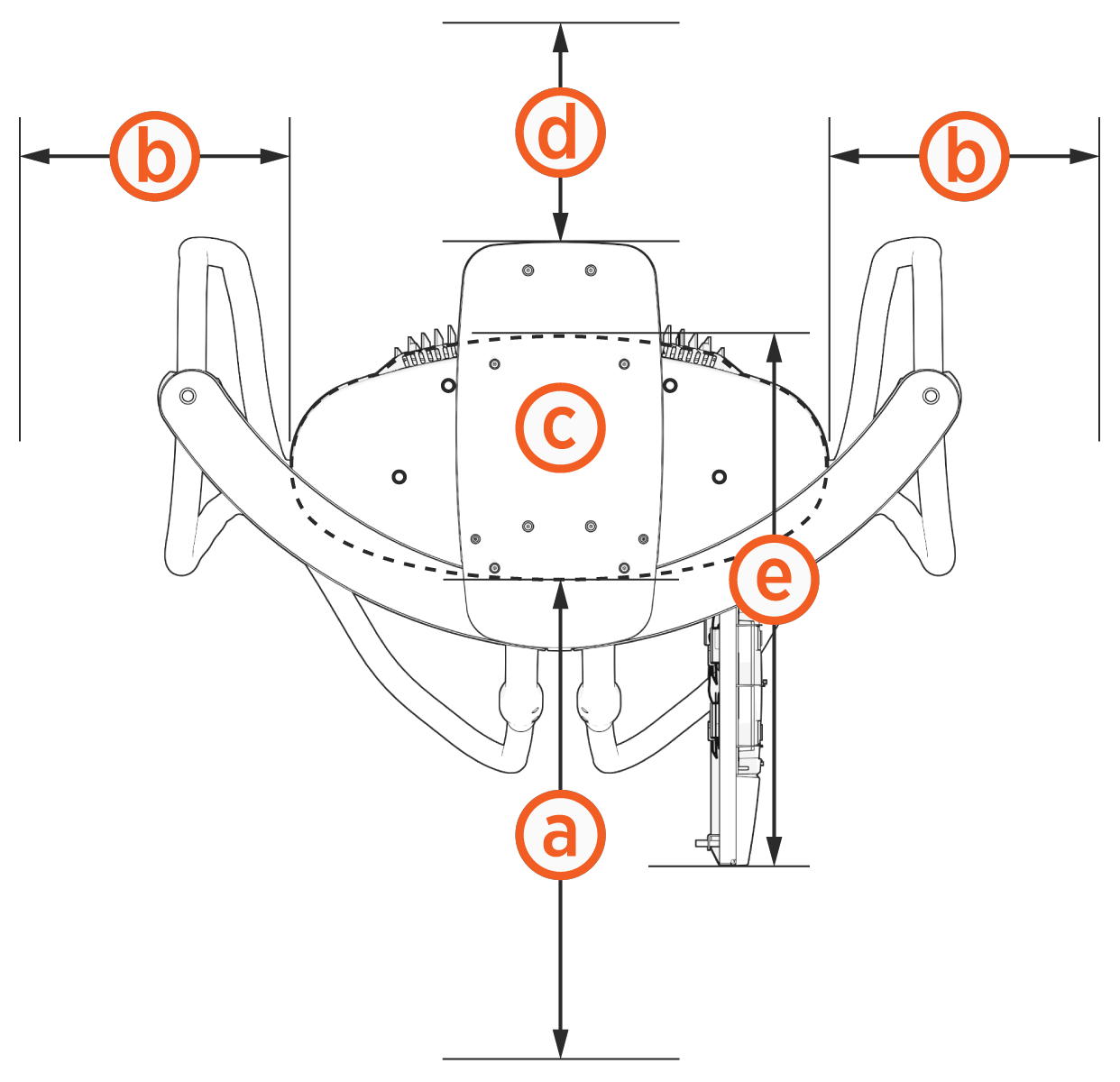
The Power Link 2000 requires minimum site and service clearances listed below.
| LCC Liquid Cooled Cable
|
Non-LCC Liquid Cooled Cable
|
|
|
|
|
Power Link 2000 |
Clearance |
|
|---|---|---|
|
Minimum open space |
610 mm (2 ft) |
|
305 mm (12 in) at grade, minimum
NOTE: 610 mm (24 in) recommended for user service and this 610 mm (24 in) can be shared between Power Link 2000s |
|
|
Pedestal or wall-mount |
26 mm (1 in) from top of CMK |
|
Overhead-mount |
305 mm (12 in) from top of Power Link 2000 |
|
|
Pedestal-mount |
203 mm (8 in) for non-LCC This provides service clearance for CMK
NOTE: At least 610 mm (2 ft) of clearance is required for surface conduit entry. In the case of back-to-back Power Link 2000s, each with surface conduit entry, the clearance can be shared. |
|
730 mm (28.75 in) |
|
Wheel Stops and Bollards
Bollards and wheel stops are not explicitly required by ChargePoint. However, ChargePoint recommends these best practices and considerations when designing the site:
-
Permanent bollards or wheel stops must not encroach upon the clearances listed in the clearance diagrams in this section. Removable bollards are allowed if service personnel have the ability to move them as needed.
-
Where permitted by code, wheel stops are preferred over bollards for head-in or back-in spaces.
Wheel Stops
-
When using wheel stops, consider the average vehicle overhang distance for the largest type of vehicle (passenger, bus, etc.), as well as leaving space for the driver to walk up and access the station.
-
Position wheel stops to actively block at least one wheel, without presenting a trip hazard to pedestrians walking between vehicles.
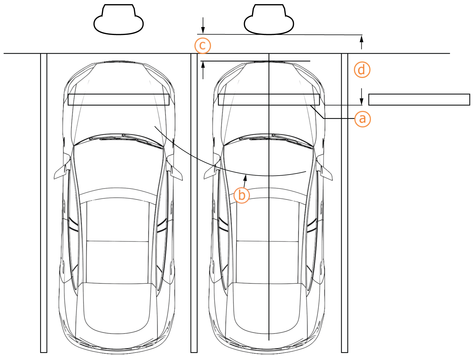
(a) Wheel stop, positioned to actively block at least one wheel
(b) Cable reach radius: 3.76 m (148 in)
(c) Recommended distance for walk-up access: 609 mm (24 in)
(d) Recommended distance between wheel stop and station: 1371 mm (54 in) for passenger vehicles
Bollards
-
When bollards are required by code, needed for snowy areas, or needed for curbside spaces, ensure bollard placement does not interfere with removing and replacing charge cables in the station’s holsters.
-
Try to minimize bollard interference with the movement of charge cables between the station and the vehicle. Bollard height is recommended to be no higher than 914 mm (36 in) where needed.
-
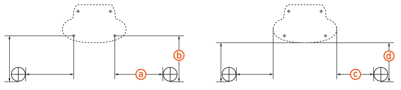
Follow the measurements listed for bollards placement:
-
Anchor bolt to bollard inside edge: 254 mm (10 in)
-
Anchor bolt to bollard front edge: 424 mm (16.7 in)
-
Power Link 2000 side to bollard inside edge: 122 mm (4.8 in)
-
Power Link 2000 front to bollard front edge: 305 mm (12 in)
-
Ventilation
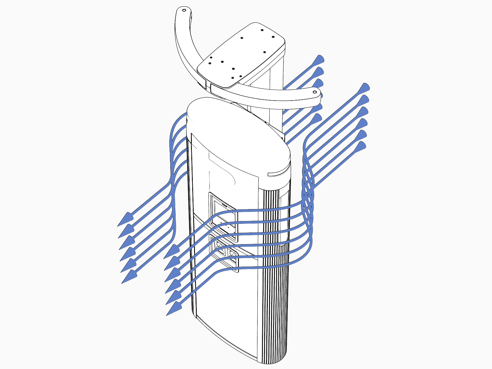
Ensure that any installation, especially an indoor installation, has adequate airflow to dissipate heat at maximum operation. The station location must allow fresh ambient airflow and must be free of any objects that might restrict airflow to the station. A station experiencing temperatures in excess of the maximum allowed operating temperature may deliver reduced maximum performance.
Power Link 2000s without liquid cooled cables require 500 W (1,700 BTU/hr) of heat rejection. Power Link 2000s with liquid cooled cables require 5.3 kW (18,000 BTU/hr).
Accessibility
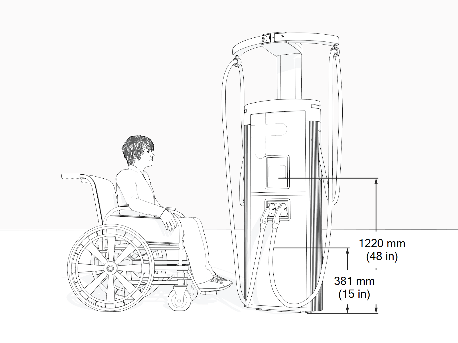
Comply with regional accessibility laws, regulations, and ordinances. The Power Link 2000 charging station must not block ramps or pathways and the height of the interactive display cannot exceed the maximum height as dictated by local laws.
Do not install Power Link 2000 on a raised concrete pad for parking spaces reserved for people with limited mobility. Power Link 2000 meets ADA height requirements when measured from a finished floor or ground plane (i.e., Power Link 2000's all operable parts, such as cable connectors and display, are no higher than 1220 mm or 48 in and no lower than 381 mm or 15 in from a finished floor or ground plane).
Signage
Refer to local and regional code to design the following elements for the site:
-
Any required re-striping of parking spaces
-
EV
Electric Vehicle or Accessible EV Electric Vehicle signs -
EV
Electric Vehicle or Accessible EV Electric Vehicle paint markings on and around the parking spaces
