Electrical Design
This section provides electrical site design specifications for Power Link 2000.
Conduit and wire size are determined based on current. Service wiring in conduit or armored cable must be run as required to comply with local electrical codes. Consult national and local codes or a project engineer to determine the grade, quality, and size of the conduit or cable.
If a site requires surface conduit entry installation, contact ChargePoint before beginning work to obtain an approved installation method. If the station is being fed power by more than two Power Blocks, surface conduit entry installation is not permitted.
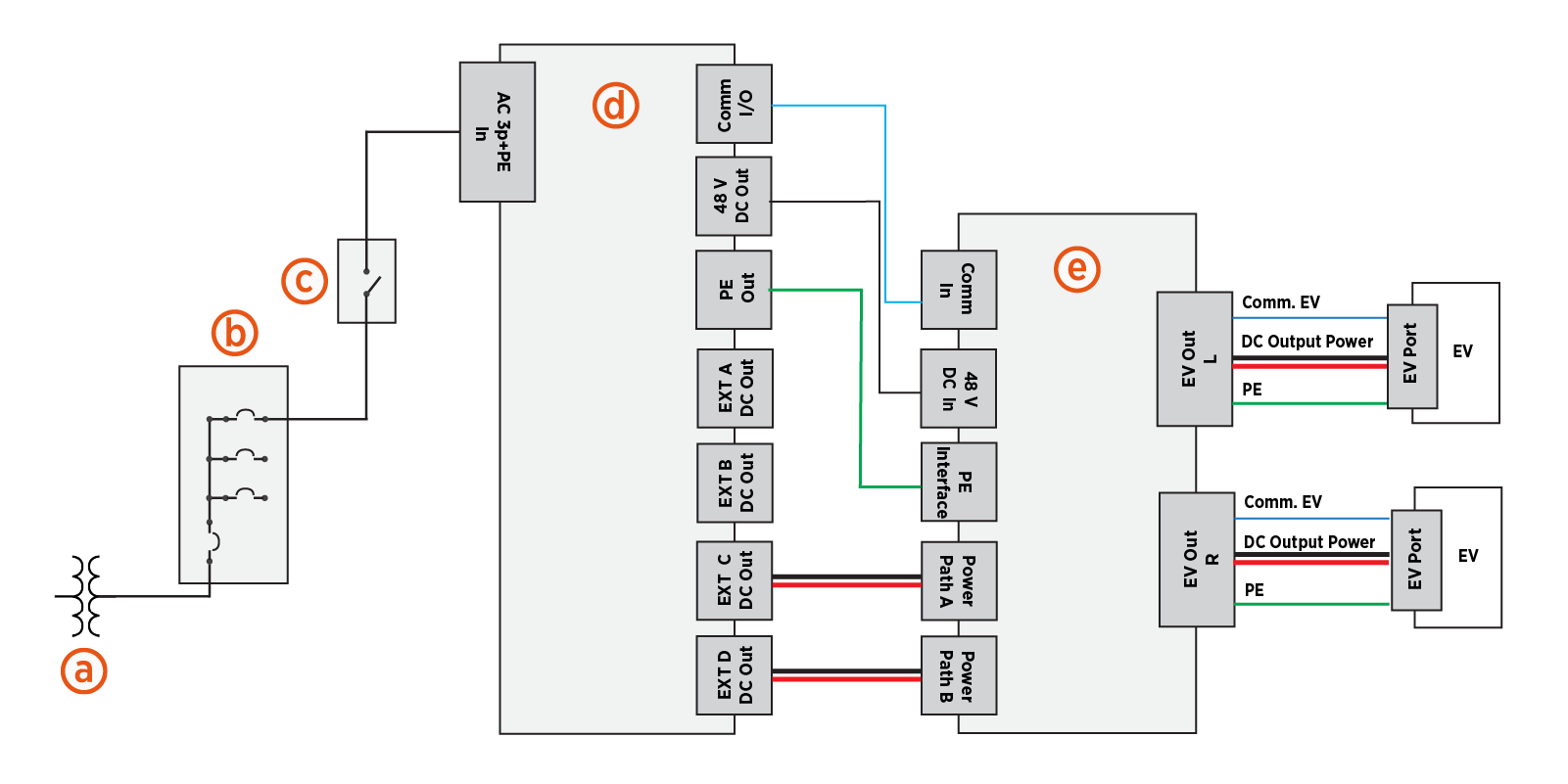
The following illustration shows a sample electrical circuit, including an optional component, for an Express cluster consisting of one Power Block 2000 feeding one Power Link 2000.
-
Transformer
-
Electrical panel with circuit breakers
-
AC disconnect switch (optional)
-
Power Block 2000 (sample power cabinet)
-
Power Link 2000
Grounding Requirements
All stations within the Express platform have metallic accessible enclosures and rely on protective earth or ground connection for protection against electrical shock.
A Power Link 2000 must be connected to a grounded, metal, permanent wiring system. The equipment‑grounding conductor shall be routed with the circuit conductors and terminated at the equipment‑grounding terminal inside the Power Link 2000.
The equipment‑grounding conductor must remain continuous and bonded in sequence from the upstream power source to the Power Link 2000. This includes installations where the upstream source is a power cabinet such as an Express Solo or Power Block 2000. Bonding must ensure that all stations in the circuit share a common protective earth path.
All grounding and bonding practices must comply with applicable local electrical codes and with the grounding requirements specified in the site design guide for the upstream power cabinet. For detailed power cabinet grounding requirements, refer to the site design guide for the upstream power cabinet.
Power Link 2000 Soft Shutdown
The soft shutdown function is an optional feature that can be installed as a way to stop a charge session on that Power Link 2000. It is not meant to safely service the Power Link 2000 or take the place of a DC maintenance switch.
To use this feature, the installer must select and mount a physical soft shutdown switch (one per Power Link 2000) with the following specifications:
-
Building wire rated to 600 V and suitable for the installation environment (e.g., dry, damp, or wet locations)
-
Normally Open (NO) configuration
-
Switch current of 2 ma
-
Switch voltage of 48 V
-
Gold contacts suggested
When creating the site drawings, consider where any soft shutdown switches should be positioned. If applicable, consider disability and accessibility regulations for your region when choosing switch locations.
Soft shutdown switch requires a dedicated conduit. For more information, refer to Conduit Requirements.
When the switch is closed, the Power Link 2000 software ends the current charging session with a normal stop, then opens DC contactors in the Power Link 2000. The station stays in this state regardless of station power, not allowing operation. Only a service technician can place the Power Link 2000 back into service after the switch is reset to Open.
WARNING: The DC power path input wires could still be energized by the power cabinet with the switch closed.
DC Maintenance Switch
If an external DC disconnect switch is used, then the switch must be configured with Normally Closed (NC) contact feedback wired into each Power Link 2000. The DC Maintenance Switch is an optional part available for the pedestal-mount Power Link 2000. It is ordered and shipped separately and is field installed.
Sequential Charging Kit
Dual output Power Link 2000s may be configured for sequential charging by field installing a Sequential Charging Kit. This kit allows Power Link 2000 to take a single power input and feed the power to either output in a sequential manner. The Sequential Charging Kit is ordered separately and is field installed.
Ethernet to USB Kit
Ethernet to USB Universal Serial Bus is an optional kit that allows an Express cluster (interconnected power cabinets and Power Link 2000s) to have a hardwired Ethernet connection with an external network server.
The Ethernet to USB Universal Serial Bus kit is installed within a single Power Link 2000, providing network connection for every node in the Express cluster. The installation requires a conduit for the Ethernet cable, which must be run from the customer server or network equipment directly to the Power Link 2000.
This kit must be ordered separately and installed in the field.
Wiring and Conduit Requirements
Refer to the Express Power Link 2000 Datasheet at ChargePoint Product Reference Documentation for full product specifications.
Ensure that the installation location is equipped with service wiring that support the station's power requirements.
Conduit and wire size are determined based on current. Service wiring in conduit or armored cable must be run as required to comply with local electrical codes. Consult national and local codes or a project engineer to determine the grade, quality, and size of the conduit or cable.
Wire Run Lengths
-
The maximum total wire run length from a power cabinet to the Power Link 2000 must not exceed 200 m (656 ft). Refer to the cluster configuration provided by ChargePoint for interconnect details.
-
For 48 V DC wire and Ethernet runs between nodes (i.e., power cabinet and Power Link 2000):
-
For non-LCC
Liquid Cooled Cable cables:-
Without power pass-through (daisy chaining), the 48 V and Ethernet wire run length between the power cabinet and Power Link 2000 can be up to 200 m (656 ft).
-
With power pass-through, the maximum total wire run length from the power cabinet to the furthest Power Link 2000 is 160 m (525 ft). Contact ChargePoint for options if greater lengths are needed.
-
-
For LCC
Liquid Cooled Cable cables:-
The 48 V and Ethernet wire run length between power cabinet and Power Link 2000 can be up to 100 m (328 ft). Contact ChargePoint for options if greater lengths are needed.
-
-
- The maximum wire run length between a Power Link 2000 and an external network connection is 200 m (656 ft). Refer to the cluster configuration provided by ChargePoint for interconnect details.
Ethernet Cable Type and Configuration
-
For Ethernet communications between any two nodes (for example, between a Power Link 2000 and an upstream power cabinet, or between a Power Link 2000 and an external network connection):
-
Distances up to 100 m (328 ft) must use outdoor-rated Cat6 Shielded Twisted Pair (STP
Shielded Twisted Pair) cable. Lesser grades of cable do not provide the required noise immunity. -
Distances between 100 m (328 ft) and 200 m (656 ft) must use an extended reach cable rated for 200 m (656 ft).
-
-
An Ethernet cable connecting a power cabinet and a Power Link 2000 must have the shield terminated at the power cabinet end.
-
An Ethernet cable connecting two daisy-chained Power Link 2000s must have the shield terminated at the end nearer to the power cabinet.
Conduit Requirements
To ensure proper fit, environmental protection, and compliance with enclosure tolerances, the following requirements apply when conduits are used:
-
The conduits must be sealed to maintain a Pollution Degree 2 environment.
-
The conduits must not have bell ends. Conduits with bell ends may interfere with tolerances inside the Power Link 2000.
-
If using conduit stub-ups in a pedestal-mount Power Link 2000, conduits must stub up between 13 and 25 mm (0.5 and 1 inch) above the mounting surface.
Conduit quantity and size - Pedestal-mount with stub-up wire entry
IMPORTANT: The following table provides the maximum size and quantity of conduits that can be installed for a pedestal-mount Power Link 2000 configured for wire entry via conduit stub-ups. The actual conduit size and quantity must be chosen based on site specific wiring requirements.
| Conduits For | Conduit Quantity x Size (O.D.) |
|---|---|
|
DC power path input wires
|
2 x 103 mm max. or 4 x 78 mm max. or 6 x 53 mm max. |
|
48 DC wires and Ethernet cable |
2 x 27 mm (*) |
|
Optional features (Ethernet to USB |
2 x 21 mm max. |
(*) 48 V DC and Ethernet wires travel in the same conduit. 27 mm conduit size is required. The quantity of conduit will depend on configuration.
Conduit quantity and size - Pedestal-mount with surface wire entry
IMPORTANT: The following table provides the maximum size and quantity of conduits that can be installed for a pedestal-mount Power Link 2000 configured for wire entry via the Surface Conduit Entry (SCE Surface Conduit Entry) kit. The actual conduit size and quantity must be chosen based on site specific wiring requirements.
| Conduits For | Conduit Quantity x Size (O.D.) |
|---|---|
|
DC power path input wires
|
2 x 78 mm max. |
|
48 DC wires and Ethernet cable |
2 x 27 mm (*) |
|
Optional features (Ethernet to USB |
2 x 21 mm max. |
(*) 48 V DC and Ethernet wires travel in the same conduit. 27 mm conduit size is required. The quantity of conduit will depend on configuration.
Conduit quantity and size - Overhead-mount with surface wire entry
IMPORTANT: The following table provides the maximum size and quantity of conduits that can be installed for an overhead-mount Power Link 2000. The actual conduit size and quantity must be chosen based on site specific wiring requirements.
|
Conduits For |
Conduit Quantity x Size (O.D.) |
|---|---|
|
DC power path input wires
|
2 x 103 mm max. or 4 x 78 mm max. |
|
48 DC wires and Ethernet cable |
2 x 27 mm (*) |
|
Optional features (Ethernet to USB |
2 x 21 mm max. |
(*) 48 V DC and Ethernet wires travel in the same conduit. 27 mm conduit size is required. The quantity of conduit will depend on configuration.
Wire Terminal and Bus Bar Locations
This section illustrates the wire terminal and bus bar locations within the Power Link 2000.
Pedestal-Mount Power Link 2000
Depending on configuration, the pedestal-mount Power Link 2000 has one or two DC power paths, named A and B. Each power path has two wire landings, an upper landing and a lower landing. Power Link 2000s with a single charging cable are configured with Power Path B landings only.
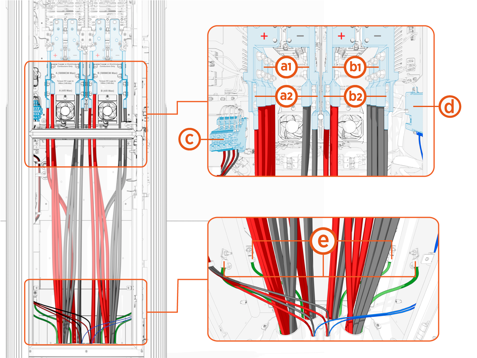
(a1) DC Power Path A, upper landing
(a2) DC Power Path A, lower landing
(b1) DC Power Path B, upper landing
(b2) DC Power Path B, lower landing
(c) 48 V DC and soft shutdown
(d) Ethernet
(e) Protective Earth
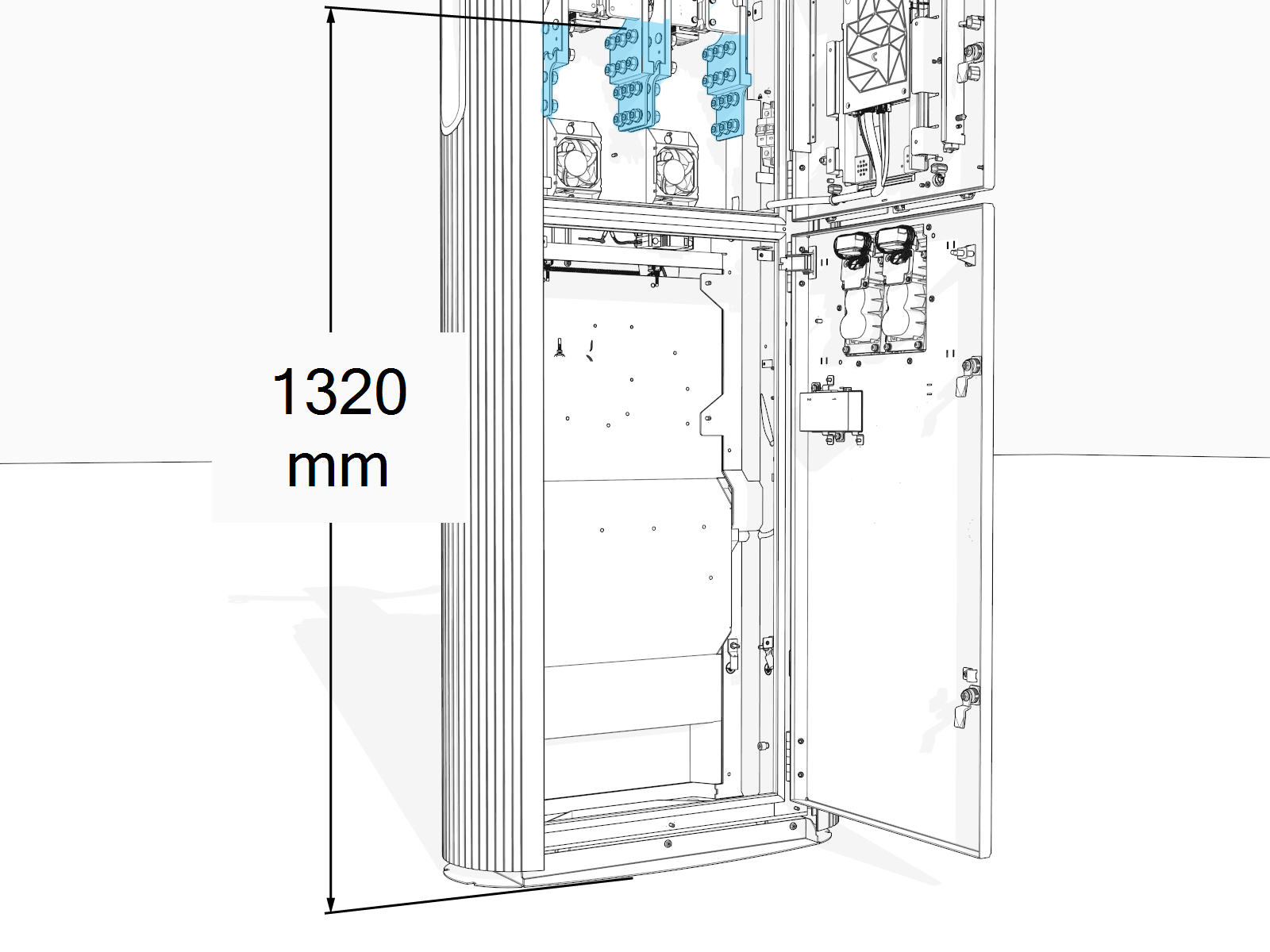
Consider the height of the DC power path bus bars above the concrete pad when determining the wire length required.
Overhead-Mount Power Link 2000
Depending on configuration, overhead-mount Power Link 2000s have one or two DC power paths, named A and B. Each Power Path has two wire landings, an upper landing and a lower landing. Single-output Power Link 2000s are configured with only a right-side charging cable and Power Path B landings only.
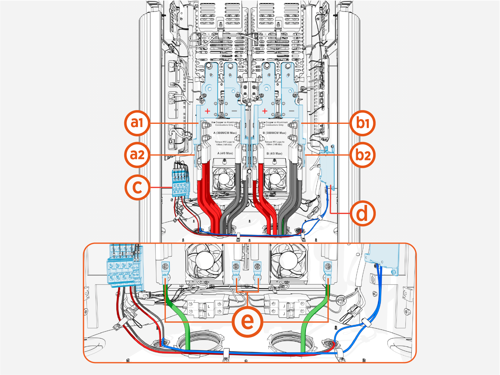
(a1) DC Power Path A, upper landing
(a2) DC Power Path A, lower landing
(b1) DC Power Path B, upper landing
(b2) DC Power Path B, lower landing
(c) 48 V DC and soft shutdown
(d) Ethernet
(e) Protective Earth
Wire Specifications
-
For DC power path high-current wiring:
-
Use copper or aluminum wires rated for 90 °C (194 °F).
-
Wires must use insulation suitable for at least 1000 V.
-
-
For 48 V DC and soft shutdown wiring, use copper wiring only. Select wire types suitable for the installation environment (e.g. dry, damp, or wet locations), and rated for 1000 V and at least 75 °C (167 °F).
-
All landing bus bars are nickel-plated. Use the proper type of lug based on the conductor and bus bar material.
-
When using aluminum lugs, ChargePoint recommends using an appropriate antioxidant compound on aluminum conductors when terminating into tin-, nickel-, or silver-plated lugs, where required by code or specified by the lug manufacturer.
|
Wire |
Quantity |
Size |
Termination |
|---|---|---|---|
|
DC Power Paths A and B (max. 500 A per landing) |
Max. 12 wires per Power Path (three wires per pole on each landing) |
Upper landings: Max. 150 mm2 (*) |
Lug: Long barrel and tongue with two holes spaced 44.5 mm (1.75 in) apart and sized for M12 studs. Max. lug tongue width: 31 mm (1.25 in) for upper landings, 25.9 mm (1 in) for lower landings. Aluminum lug max. tongue thickness: 10 mm (0.4 in) for upper landings, 5 mm (0.2 in) for lower landing. |
|
Lower landings: Max. 120 mm2 |
|||
|
Protective Earth |
Max. 6 wires (one per Power Block) |
Refer to the local code for size; max. 50 mm2 |
Lug: Short barrel and tongue with single hole, sized for M6 stud. |
|
48 V DC |
Max. 8 wires (four wire pairs; each pair has one wire per pole) |
16 mm2 |
Stripped wire end or ferrule |
|
Ethernet |
Max. 4 cables |
Outdoor-rated Cat6 STP |
RJ45 connector |
|
Soft shutdown switch(***) |
2 wires |
2.5 mm2 |
Stripped wire end or ferrule |
(*) If utilizing both upper and lower landings, the maximum DC input power path wire size is 120 mm2. (**) The required Ethernet cable type depends upon the cable run length. Refer to Ethernet Requirements for details. (***) Soft shutdown switch is an optional feature.
