Civil and Mechanical Design
This section describes civil and mechanical site design guidelines for Power Block 2000.
Dimensions
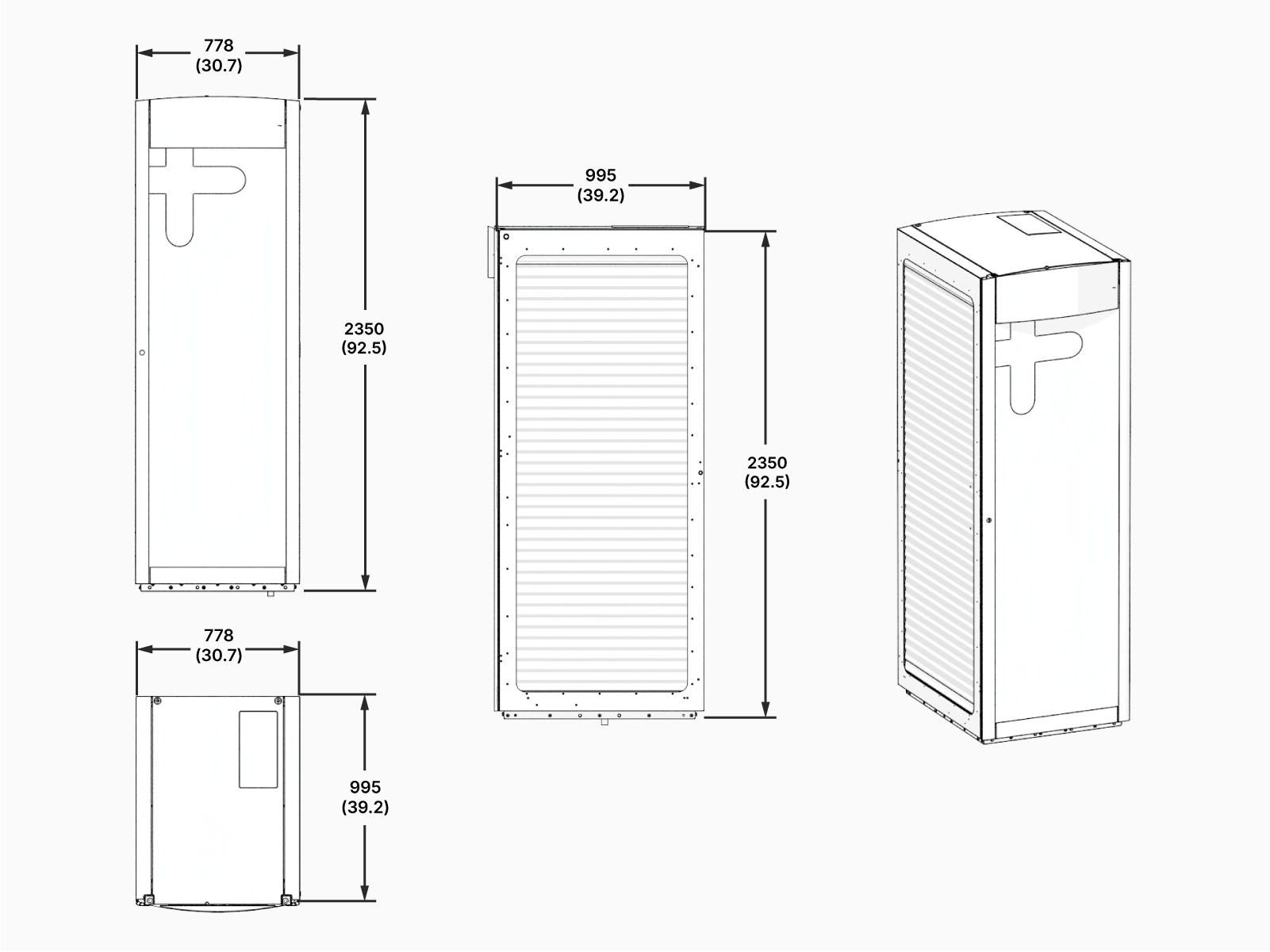
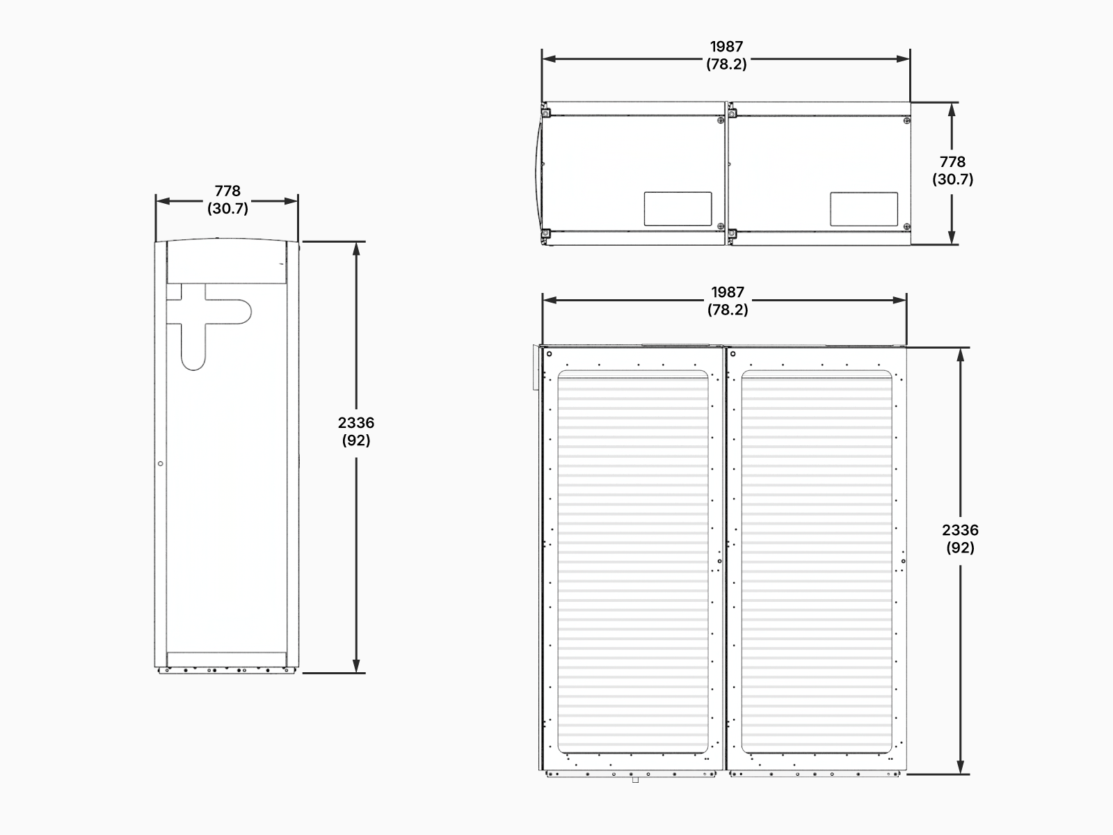
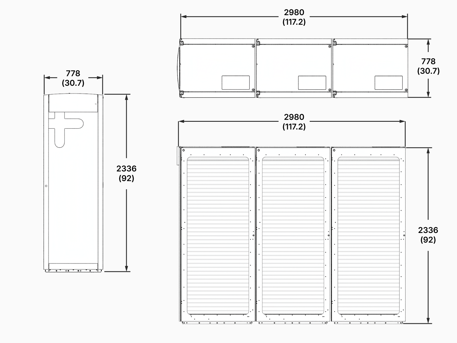
Images given in this section are not to scale. Measurements appear in metric units (mm), followed by imperial equivalents (inches).
Single-Cabinet
Double-Cabinet
Triple-Cabinet
Weights
The following enables calculation of the Power Block 2000 weight, depending on its configuration:
| Component | Weight |
|---|---|
|
Power Block 2000 – Single-cabinet (fully loaded) |
1300 kg (2866 lb) |
| Power Block 2000 – Double-cabinet (fully loaded) |
2600 kg (5732 lb) |
| Power Block 2000 – Triple-cabinet (fully loaded) |
3900 kg (8598 lb) |
|
AC power module (single module) |
93 kg (205 lb) |
|
DC power module (single module) |
68.5 kg (151 lb) |
Mount Specifications
Concrete Pad Specifications
The Power Block 2000 must be installed on a concrete pad or engineered foundation. The concrete pad may be either newly poured or an existing concrete surface, provided it meets the requirements below.
Surface requirements
The concrete surface must be smooth and level. If an existing surface does not meet this requirement, a localized leveling pad must be poured.
Adhering to the level surface requirement is critical for cabinet stability, proper alignment, and long-term structural performance.
New concrete pad requirements
A new concrete pad may be:
-
Site‑specific, designed by a licensed structural engineer, or
-
Selected from the standard pad specifications provided in this section.
Conservative concrete stability specifications for Power Block 2000 are listed below for the following design scenarios:
-
170 mph wind, high seismic, Class 3 Soil
-
170 mph wind, high seismic, Class 4 Soil
-
170 mph wind, high seismic, Class 5 Soil
-
140 mph wind, lower seismic, Class 3 Soil
-
140 mph wind, lower seismic, Class 4 Soil
-
140 mph wind, lower seismic, Class 5 Soil
All scenarios assume the following baseline requirements:
-
Concrete Strength: Minimum design compressive strength of 2500 PSI.
-
Anchor bolts: M20 threaded, ASTM F1554 Grade 55, hot-dip galvanized. Bolts shall be embedded to the depth specified in the table below.
-
The anchor bolt pattern shall be centered within the designed stability area of the concrete pad.
Single-Cabinet Concrete Stability Specifications:
|
Design Scenario # |
Pad Width |
Pad Length |
Pad Thickness |
#N1 @ S1 O.C. |
#N2 @ S2 O.C. |
Anchor Embedment |
|---|---|---|---|---|---|---|
|
1 |
1997 mm (79 in) |
2214 mm (87 in) |
457 mm (18 in) |
#5 @ 304 mm (12 in) O.C. |
#5 @ 304 mm (12 in) O.C. |
305 mm (12 in) |
|
2 |
1997 mm (79 in) |
2214 mm (87 in) |
610 mm (24 in) |
305 mm (12 in) |
||
|
3 |
1997 mm (79 in) |
2214 mm (87 in) |
457 mm (18 in) |
305 mm (12 in) |
||
|
4 |
1540 mm (61 in) |
1757 mm (69 in) |
457 mm (18 in) |
203 mm (8 in) |
||
|
5 |
1692 mm (67 in) |
1909 mm (75 in) |
457 mm (18 in) |
203 mm (8 in) |
||
|
6 |
1540 mm (61 in) |
1757 mm (69 in) |
457 mm (18 in) |
203 mm (8 in) |
Double-Cabinet Concrete Stability Specifications:
For details, contact ChargePoint at chargepoint.com/support.
Triple-Cabinet Concrete Stability Specifications:
For details, contact ChargePoint at chargepoint.com/support.
In extreme environmental conditions, a larger pad may be required. Conversely, sites with less stringent wind, seismic, or soil conditions may allow for a smaller pad, subject to engineering approval.
Existing pad requirements
An existing concrete pad may be used if it meets one of the conservative stability specifications listed above, or if it is evaluated and approved by a structural engineer using the parameters below.
The table below consolidates all required inputs—whether provided directly here or defined elsewhere in the guide—so the stuctural engineer receives a complete and consistent set of values.
| Parameter | Value |
|---|---|
|
Weight |
See Weights |
|
Height x width |
See Dimensions |
|
Frontal area |
Height x Width as given in Dimensions |
|
Center of gravity height |
1349 mm (53.1 in) |
|
Anchor bolts size and quantity |
M20 (x4 per cabinet) |
|
Anchor bolts embedment depth |
Minimum 203 mm (8 in) |
|
Anchor bolts pattern |
Anchor Bolt Pattern
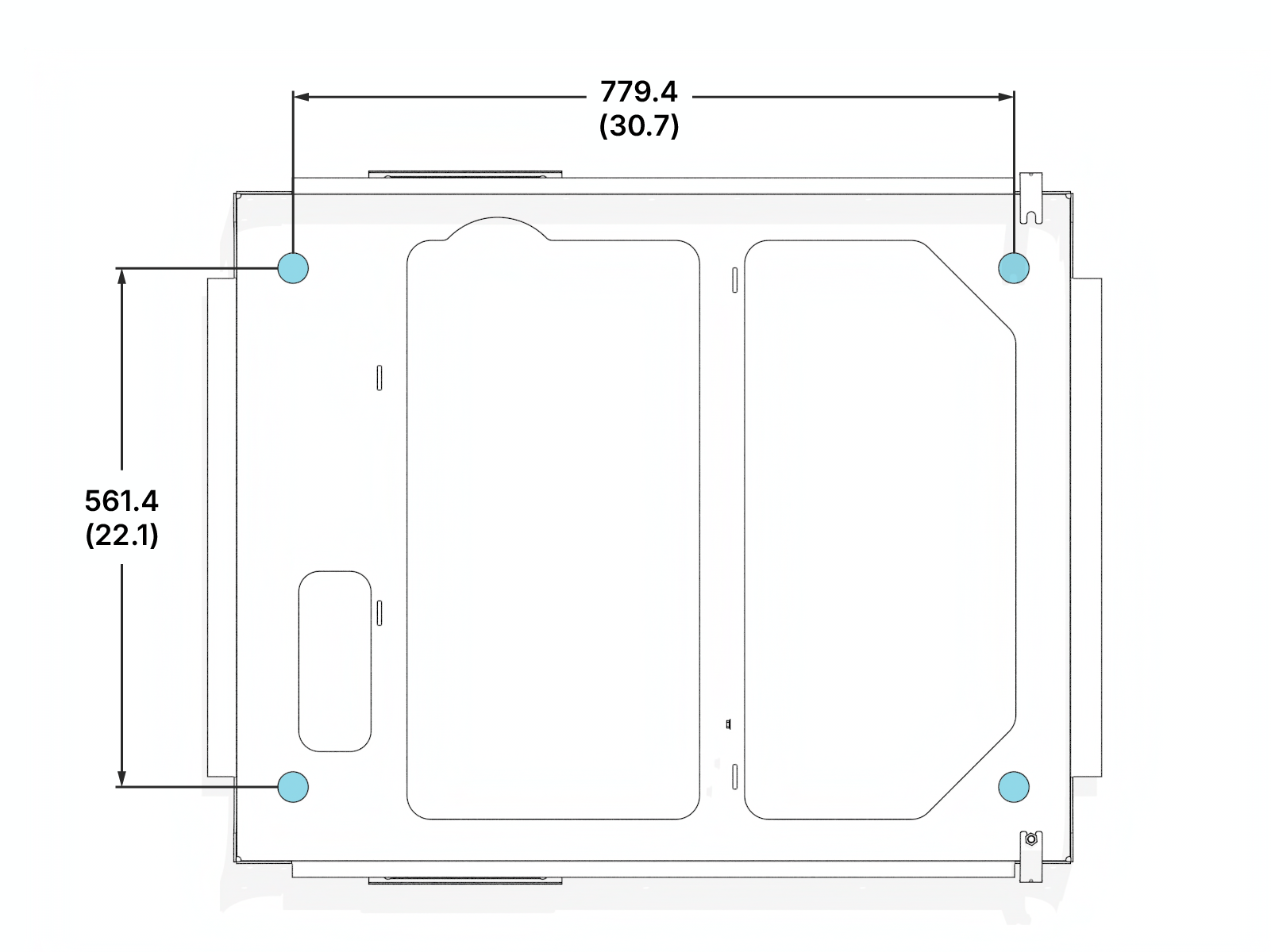
Images given in this section are not to scale. Measurements appear in metric units (mm), followed by imperial equivalents (inches).
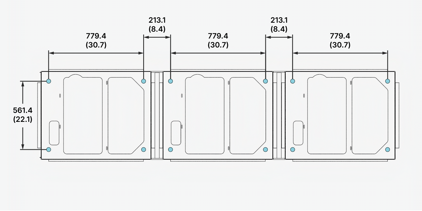
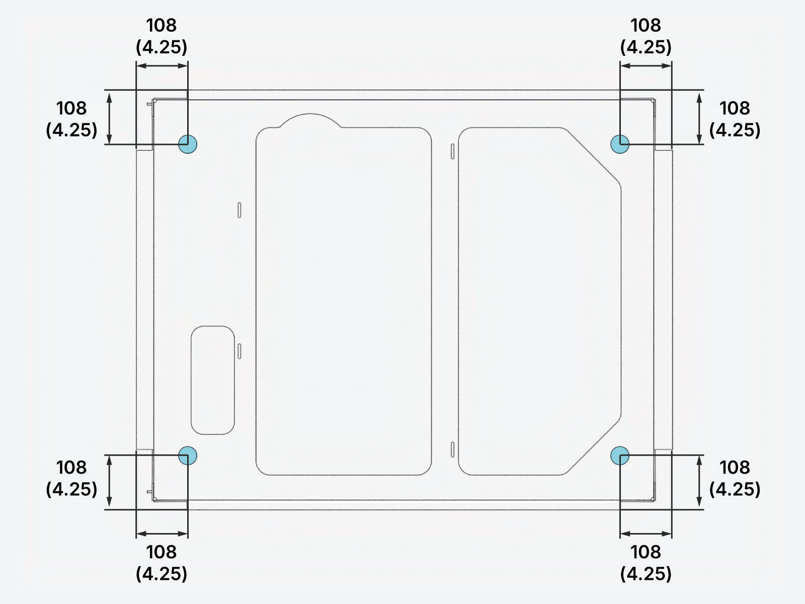
Power Block 2000 mounts over anchor bolts embedded in a concrete pad with the anchor bolt pattern shown below. The image perspective is looking from the ground up at the bottom plate of the cabinets.
Single cabinet anchor bolt pattern:
Multi-cabinet anchor bolt pattern:
The distance from the center of each anchor bolt to its adjacent enclosure walls is 108 mm (4.25 in).
Standard Mount
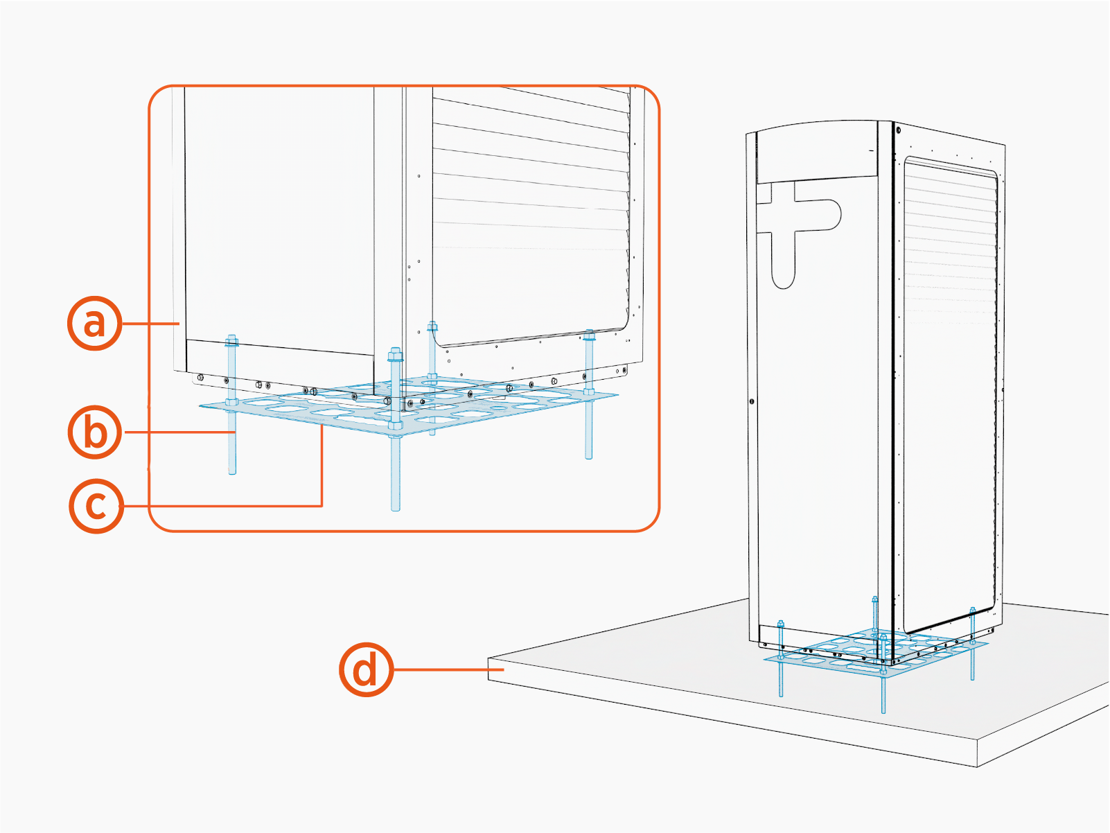
The most common mounting method for Power Block 2000 is a new pad installation using a Concrete Mounting Template (CMT) and conduit stub-up wire entry.
-
The Power Block 2000 (a) mounts onto four M20 anchor bolts (b) exposed 127 mm (5 in) above the concrete pad.
-
The CMT (c) is embedded into a newly poured concrete pad (d) to align anchor bolts and underground stub-up wiring conduits. (Conduits are not shown in illustration.)
-
The CMT is shipped separately and must be assembled onsite before pouring the concrete pad.
- One CMT is required beneath each Power Block 2000 cabinet.
-
The CMT must be embedded with its top panel positioned 51 mm (2 in) below the concrete surface.
Concrete Mount Template
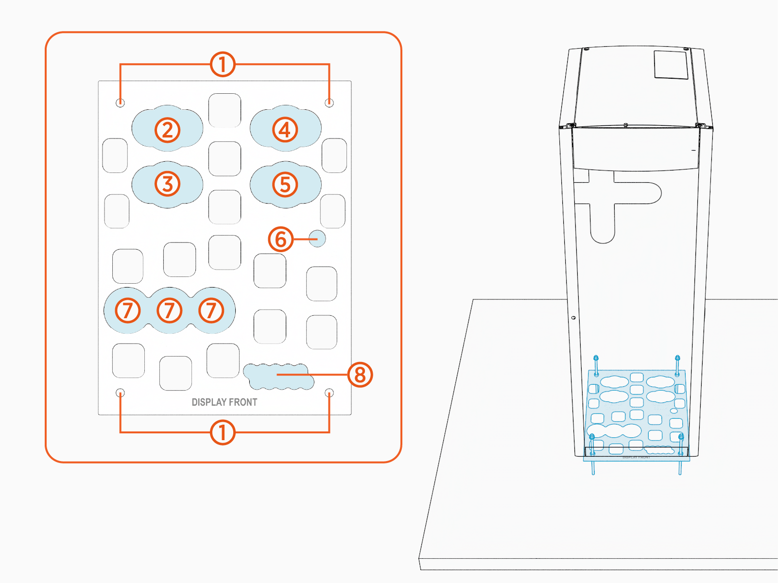
The concrete mount template (CMT) positions the anchor bolts and wire entry points as shown below.
|
Ref |
4 DC Output |
8 DC Output |
|---|---|---|
| (1) |
M20 anchor bolts |
|
| (2) |
EXT D wires |
EXT G and EXT H wires |
| (3) |
EXT C wires |
EXT E and EXT F wires |
| (4) |
EXT B wires |
EXT C and EXT D wires |
| (5) |
EXT A wires |
EXT A and EXT B wires |
| (6) |
Shunt trip wires |
|
| (7) |
AC input wires |
|
| (8) |
48 V DC output, Ethernet, and Safety Hub wires |
|
For conduit quantity and size requirements, refer to Conduit Requirements.
Surface Mount
Power Block 2000 may be installed on an existing concrete surface in accordance with the following guidelines:
-
The concrete surface must be inspected and approved by a structural engineer using the structural parameters given in Existing Pad Structural Analysis Parameters.
Verify the anchor bolt embedment for structural strength.
-
The anchor bolts must be installed in the concrete surface as follows:
-
Anchor holes are drilled into the concrete using the anchor bolt pattern given in Anchor Bolt Pattern. The holes are drilled to a depth so that 127 mm (5 in) of each anchor bolt is exposed above the concrete pad.
-
Anchor bolts are epoxied into the holes. Use an epoxy with a minimum bonding strength of 11.7 MPa, compressive strength of 82.7 MPa minimum, and tensile strength of 49.3 MPa minimum. Examples include Hilti HIT-RE 500 V3 (normal cure) or Hilti HIT-HY 200-A (fast cure).
-
Epoxy is required only if embedding anchor bolts into an existing concrete pad. It is not applicable for a new concrete pour with CMT.
-
Different epoxy types have different cure times at various temperatures. Check local temperatures for the site in advance to help choose an appropriate epoxy.
-
-
-
The anchor bolts must be hot dip galvanized. In coastal or other high‑corrosion environments, consult a corrosion specialist to determine an appropriate bolt material and coating system.
-
Surface mounted Power Block 2000 must utilize surface conduit entry.
Surface Conduit Entry
Power Block 2000 can be installed on a platform for surface conduit entry. Contact ChargePoint for more information.
Drainage
Ensure any site slopes, walls, or fencing do not trap water around the installation site.
Flood Plane
Power Block 2000 is designed for a 61 mm (2.4 in) flood plane. If the site has a flood plane greater than 61 mm (2.4 in) for a 100-year flood event, consider installing Power Block 2000 on a raised concrete pad.
WARNING: Exposing Power Block 2000 to over 61 mm (2.4 in) of standing water could create an electrocution, shock, or fire hazard.
If a Power Block 2000 has been exposed to standing water, cut power to the component and contact ChargePoint before the component is powered on.
Clearances
Power Block 2000 has clearance requirements on its intake (right) and exhaust (left) sides for installation, service, maintenance, and ventilation.
The side doors can be swung open on their hinges, allowing for convenient access for service and maintenance. If needed, the doors may be removed from the cabinet for service access.
In some installation scenarios, an opened side door may obstruct access to the cabinet, such as shown below (Option 1). Installing the cabinet rotated 180 degrees (Option 2) allows full service access without door removal.
| Option 1 | Option 2 | |
| Service Access: Blocked (door removal required) |
Service Access: Clear |
|
|
|
|
|
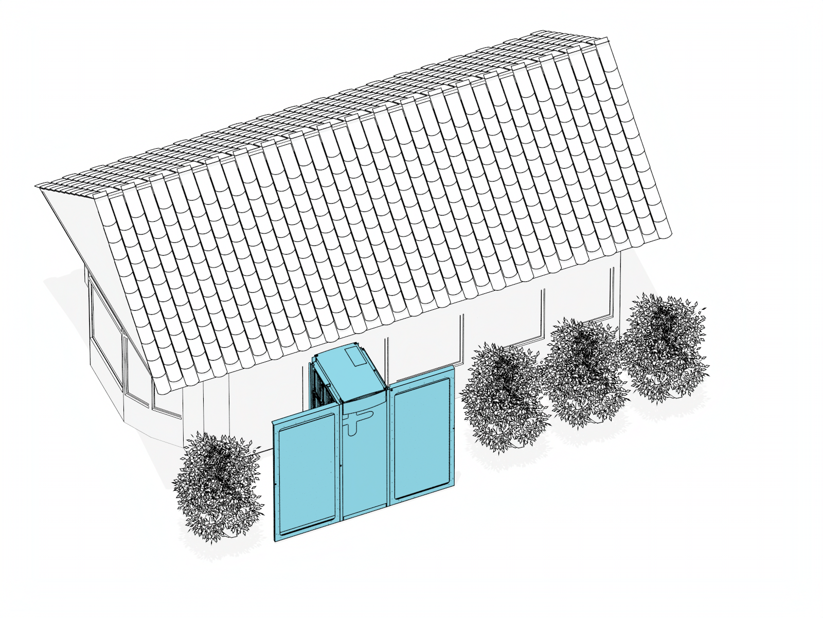
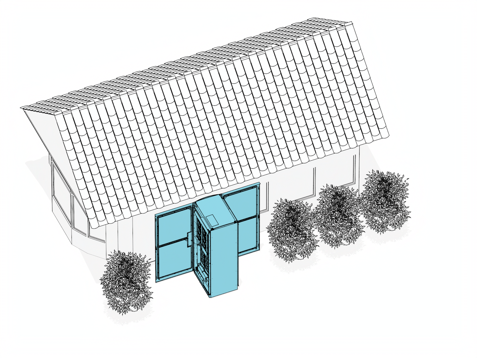
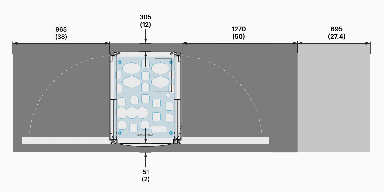
Mandatory and recommended clearance requirements for the single-cabinet Power Block 2000 are given below. The figure shows a top-down view of the Power Block 2000 cabinet overlaid on the CMT.
Images given in this section are not to scale.
Measurements appear in metric units (mm), followed by imperial equivalents (inches).
|
|
Mandatory clearance area | |
|
|
Recommended additional clearance area |


The recommended additional clearance improves serviceability. If this clearance is not available, the door may need to be removed during service.
The ground within the defined mandatory clearance areas must be firm, stable, at grade (+/- 13 mm or 0.5 in), and free of any elevation changes. The same is required if the recommended clearance area is maintained. This ensures safe access when working with tools such a module lifter, ladders, or similar equipment. Failure to maintain the required clearances or to ensure proper ground conditions may obstruct or prevent essential service operations or result in damage to the product.
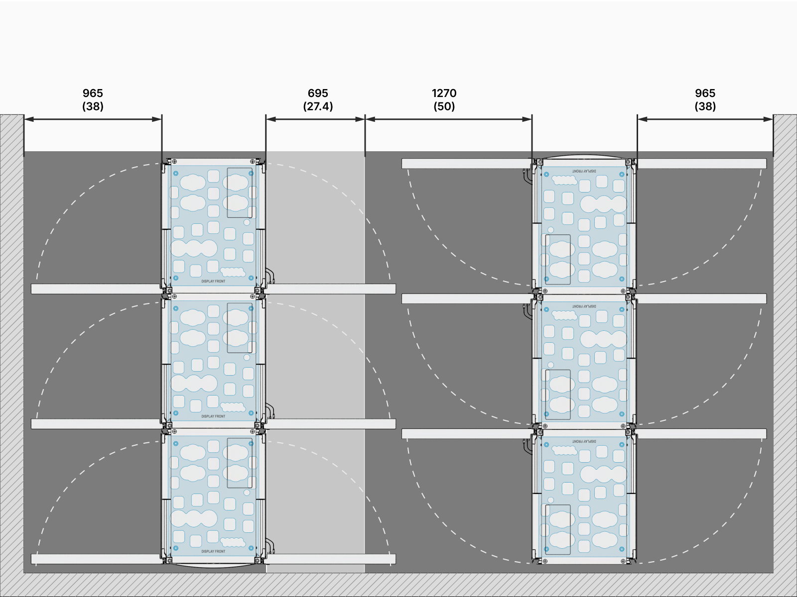
Power Block 2000s installed side by side may share clearance areas, as shown below. When installing multiple rows of cabinets, orient the rows so that the air intakes face each other to ensure proper thermal management.
|
|
Mandatory clearance area | |
|
|
Recommended additional clearance area | |
|
|
Wall, fence, or other obstruction |

When sharing side clearances, the recommended additional clearance area is highly advised.
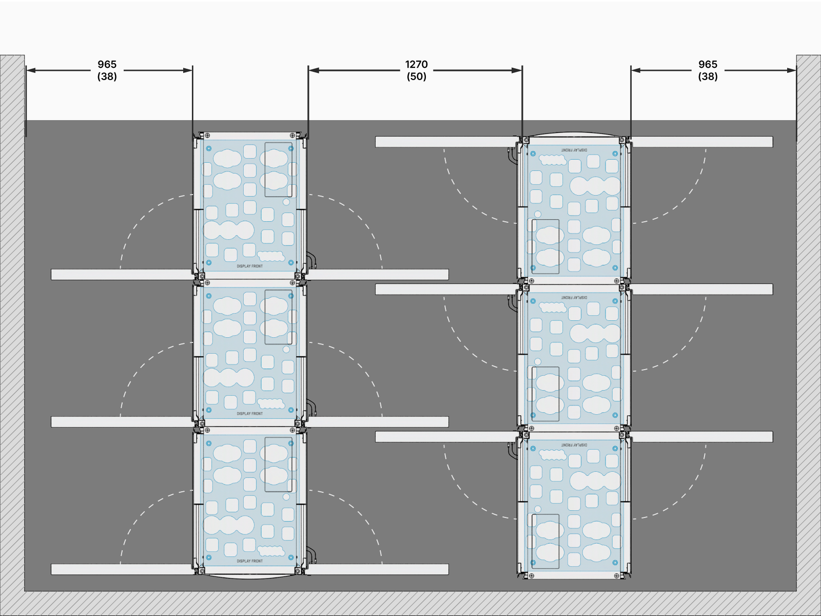
The figure below shows the minimum footprint for two triple‑cabinet Power Block 2000s installed side by side.
|
|
Mandatory clearance area | |
|
|
Wall, fence, or other obstruction |
In the minimum footprint layout shown above, the surrounding wall limits access, so the doors must be removed for service at two of the aisles.
Additionally, follow the clearance guidelines below:
-
The status LEDs must not be obstructed from view. See Exterior Parts for the location of the status LEDs.
-
After site make-ready, the only way to confirm that clearance requirements have been met is to inspect the position of the anchor bolts. See Anchor Bolt Pattern for the distance between the anchor bolts and the cabinet walls.
-
Check local and regional codes for any additional clearance requirements regarding safety, high voltage equipment, and accessibility requirements.
-
For any questions about allowable layouts, contact ChargePoint.
Bollards
Bollards are not explicitly required by ChargePoint. If applicable, ChargePoint recommends these best practices and considerations when designing bollards for the site:
-
Permanent bollards must not encroach upon the clearance areas described in Clearances.
-
Removable bollards are allowed if service personnel have the ability to move them as needed.
Bollards and wheel stops each has advantages and disadvantages. Factors to consider include: cosmetics, usability, accessibility and vehicle types.
Wheels stops offer the following advantages:
-
Clean look
-
Less chance of cables getting tangled with bollards
Bollards offer the following advantages:
-
Larger vehicles and sites with mixed vehicle sizes that have different overhangs (trucks vs. light duty vehicles)
-
More visibility while backing up
Ventilation
Intake vents are located on the right side of the Power Block 2000, and exhaust vents are on the left side when facing the front of the cabinet. When positioning multiple Power Block 2000s, position intake and exhaust sides of the cabinet to avoid recirculation.
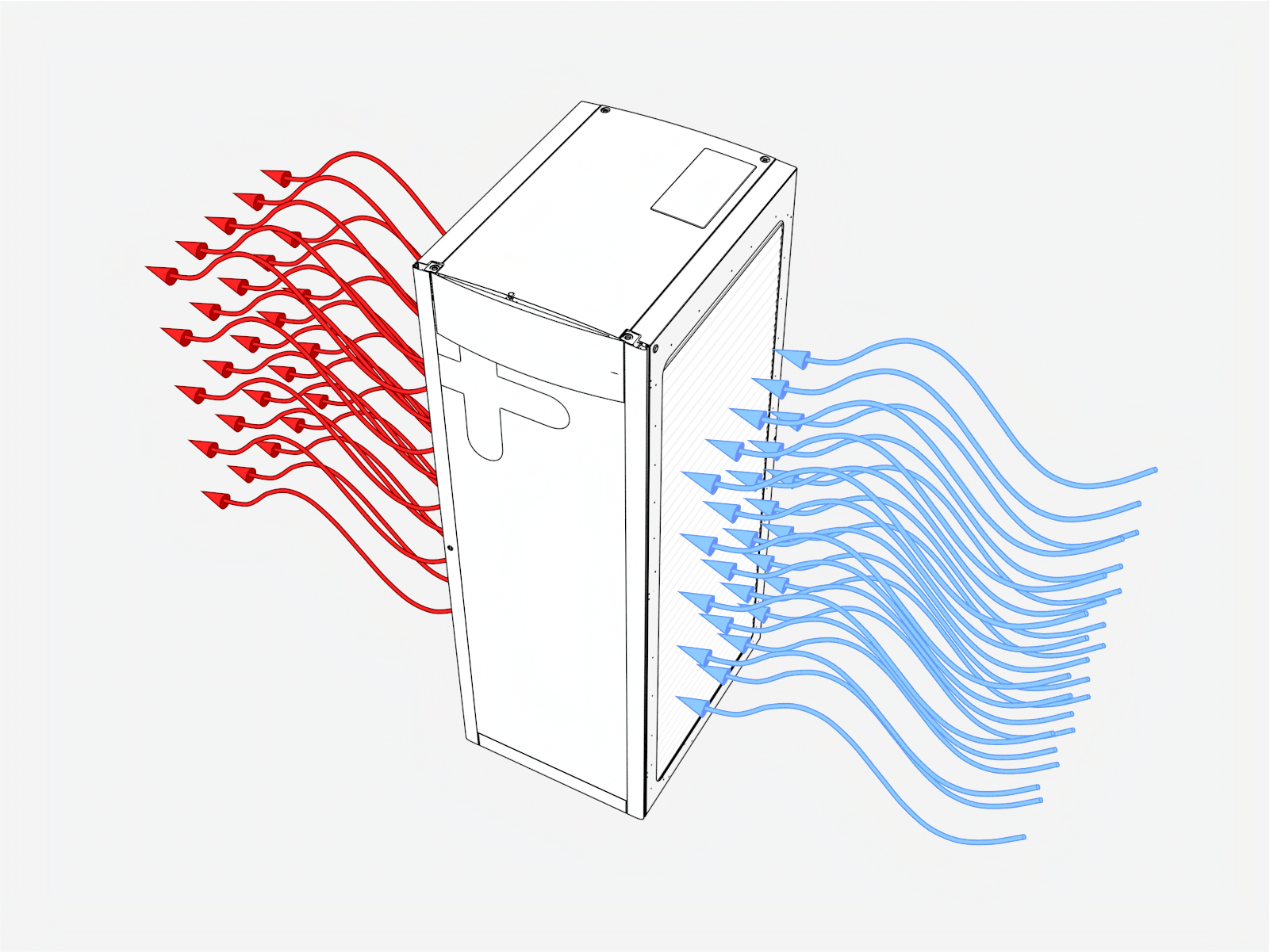
Power Block 2000 requires 33 kW (112,600 BTU/hr)) of heat rejection.
Signage
Refer to local and regional code to design the following elements for the site:
-
Any required re-striping of parking spaces
-
EV
 Electric Vehicle or Accessible EV Electric Vehicle signs
 -
EV
Electric Vehicle or Accessible EV Electric Vehicle paint markings on and around the parking spaces
