Electrical Design
At a minimum, each AC charging station requires the following:
-
A dedicated single phase or three phase electrical circuit from 10 A to 40 A
-
Conductor wiring and circuit protection sized in accordance with all applicable codes
The Flex Plus charging stations support the following maximum output configurations:
-
Single-phase: up to 7.4 kW (32 A)
-
Three-phase: up to 22 kW (32 A)
Some jurisdictions may restrict the maximum output of the charging station. Check with your local authority for any applicable requirements before finalizing the electrical configuration.
Refer the Flex Plus datasheet at ChargePoint Product Reference Documentation for information about the following:
-
Electrical input
-
Electrical output
-
Mounting and functional interfaces
-
Safety and connectivity features
-
Safety and operational ratings
General Wiring Considerations
Ensure that the installation location is equipped with service wiring that supports the charging station’s power requirements.
Conduit and wire size are determined based on the length of runs from the electrical panel to the station location. Service wiring must be run through conduit to comply with local electrical codes. Consult national and local codes or a project engineer to determine the grade, quality, and size of the conduit or cable.
Attach the conduit with a listed adapter. Use a sealing method that meets all applicable code requirements.
For full product specifications, refer to the Flex Plus Datasheet.
Wall Mount Considerations
-
Flex Plus wall mounted charging stations use surface mount wiring.
-
When pulling electrical wiring for wall mount stations, the conduit and wire must be brought to the location where the stations will be mounted. Flex conduit is typically used to bring the wire to the station. Wiring is brought in through knock outs in the back and the bottom of the charging station.
Pedestal Mount Considerations
-
To mount a Flex Plus charging station on a pedestal, you need to order the pedestal separately from ChargePoint.
-
Flex Plus pedestal mounted charging stations typically require service wiring installed underground to enter through the bottom of the station.
-
When pulling electrical wiring for Flex Plus pedestal mount, ensure at least 1.3 m (51 in) of wire remains above grade.
Conduit
The outside diameter of conduit must not exceed 42 mm (1.65 in). Conduit stub-ups measured from the base of the pedestal or the ground must be at least 457 mm (18 in).
Electrical Supply Requirements
Wiring must be sized in accordance with all applicable codes for continuous load devices. The main standard for cable size is based on IEC 60364-5-52:2009 and IEC 60364-5-54:2011. The AC terminal accepts stranded or solid conductors up to 16 mm2. The appropriate size depends upon the distance between the electrical panel and the charging station installation site and the maximum current in the circuit.
To ensure reasonable efficiency of operation, ChargePoint recommends that branch circuit conductors be sized to limit voltage drop to no more than 3%, and that the combined voltage drop for feeder and branch circuits not exceed 5%.
When planning multiple EV Electric Vehicle charging stations, it is best practice to separate non-continuous from continuous loads, with all branch circuits for EV Electric Vehicle charging on a dedicated electrical panel assembly with adequate circuit breakers. When sizing new electrical panels dedicated for EV Electric Vehicle charging, all branch circuits must support continuous load.
Flex Plus stations are designed for connection and operation on rated voltages of 230 V +/- 10% (line to neutral) or 400 V +/- 10% (line to line) at 50 Hz.
Ensure that the following are addressed before you proceed:
Use copper conductors only.
Use circuit breaker at the electrical panel with the recommended capacity.
All power and ground connections (especially those at the breaker) are clean, tight, and torqued to specification. Remove all oxide from all conductors and terminals before connecting wiring.
The following table lists the required breaker ratings. Select the appropriate breaker rating based on the maximum current.
|
Maximum Current Output |
Required Breaker Rating |
|---|---|
|
32 A |
40 A |
|
25 A |
32 A |
|
20 A |
25 A |
|
16 A |
20 A |
|
12 A |
16 A |
|
8 A |
10 A |
This table provides the required breaker ratings per circuit. Multiple stations can be installed on a single circuit using power management.
Be aware of these requirements before installing the charging station:
-
Flex Plus is Class I equipment. Power supply must provide a PE conductor and the unit must be grounded. The charging station must always be connected to protective earth (PE).
-
Reserve a power source exclusively for the charging station and ensure that it complies with HD 60364-7-722:2018.
-
Upstream short circuit protection should be a circuit breaker, 4 poles, curve C, with a nominal current greater than or equal to the maximum current expected (at least 6 kA lcc)
Consult your electricity grid operator regarding requirements for local regulations. Depending on the desired rated power, the installation of the charging station may require registration with and/or approval by your electricity grid operator.
UK Requirements
There are specific requirements for EV Electric Vehicle charging station installations within the UK. In most of the locations, the installation type follows a TN-C Terra Neutral Combined-S scheme (PME supply) which, according with the general standards for EV Electric Vehicle charging stations, is not allowed. Flex Plus stations follow all the relevant safety requirements in accordance with IEC 61851-1:2018 and IEC 60364-7-722. Any extra safety requirement caused by the installation type must be discussed with the Distribution Network Operator (DNO).
Flex Plus is a Class 1 product. All metallic parts accessible are connected to the main earth terminal. Installation of the earth connection to the EV Electric Vehicle charging station is required.
Flex Plus charging stations are designed to be installed on a TN-S Terra Neutral Separate system and can be installed on TT earth systems.
Terra Neutral Separate type shall be considered as TN-C Terra Neutral Combined-S type.Following BS 7671-7-722, clause 722.411.4, ChargePointFlex Plus charging stations must not be installed in a TN-C Terra Neutral Combined-S or Protective Multiple Earthing (PME) facility if the Flex Plus charging station is located outdoors or the charging station is indoors but the EV Electric Vehicle will be parked outdoors, unless one of the clauses (i) to (v) of BS 7671-7-722, clause 722.411.4 are fulfilled.
Flex Plus charging stations do not include a PME detection and protection system; therefore, unless clause (i) or (ii) can be guaranteed, an external device capable of providing that detection and protection and opening all live conductors, including the PE conductor, within 5s from the moment the fault is detected, must be installed.
Grounding Requirements
Flex Plus charging stations must be connected to a grounded, metal, permanent wiring system. An equipment-grounding conductor must be run with circuit conductors and connected to an equipment-grounding terminal on the charging station.
A grounding conductor that complies with applicable codes must be grounded to earth at the service equipment or, when supplied by a separate system, at the supply transformer, or may be grounded to an earth electrode. Ensure the grounding conductor complies with all applicable codes.
Earthing Systems
TT, TN-S Terra Neutral Separate, and TN-C Terra Neutral Combined-S are supported subject to local code regulations.
Connect only to the following systems:
(a)TN-S Terra Neutral Separate 230/400 VAC, 3Ø Wye Grounded Neutral
(b)TN-C Terra Neutral Combined-S 230/400 VAC, 3Ø Wye Grounded Neutral
(c) TT 230/400 VAC, 3Ø Wye Grounded Neutral
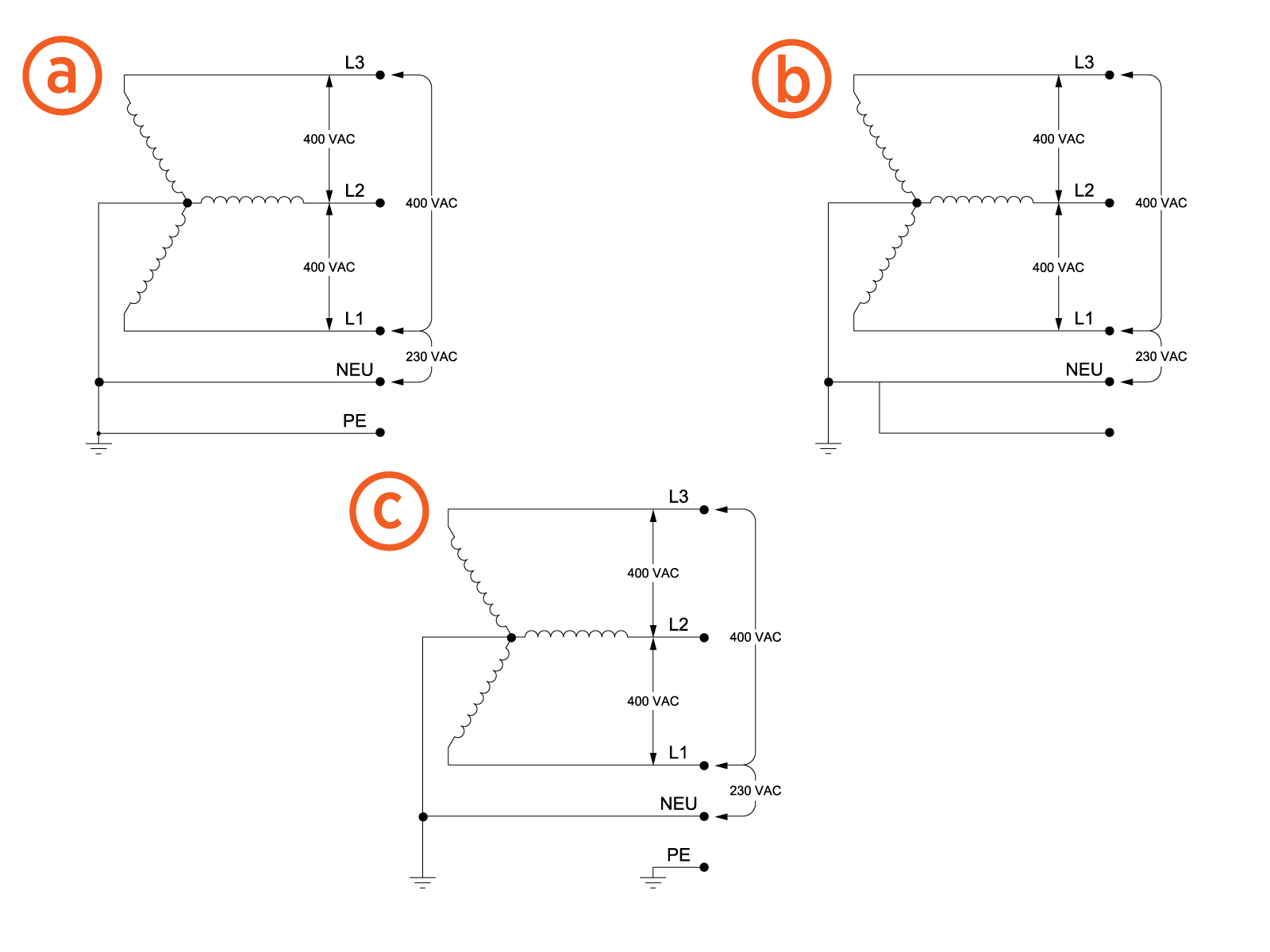
The following earthing systems are not supported:
(d) IT - (I) 400 VAC, 3Ø Wye, Floating Neutral
(e) TN-C Terra Neutral Combined (T) 400/230 VAC, 3Ø Wye Grounded Neutral
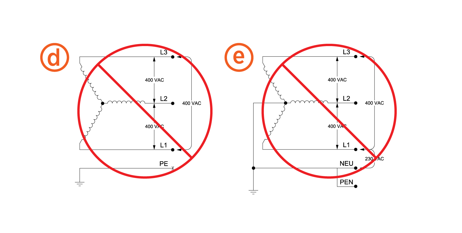
In modes TT and TN earth systems, the ground resistance must be lower than 100 Ohms if national regulations require it. Check the national regulations to verify the maximum impedance allowed.
In TT, if the ground loop impedance cannot be lower than 100 Ohms, the local earthing resistance has to be improved by changing the existing rod or putting an interconnected extra rod.
IT installation mode is prohibited. A dedicated transformer might be used to modify the system to a TN-S Terra Neutral Separate. Check local regulations for more information.
Voltage between neutral and protective earth conductors of the installation shall not exceed 10 Vrms maximum. If above condition is not met, it is necessary to identify the origin of the fault voltage and apply a corrective measure in order to commission the EVSE Electric Vehicle Supply Equipment.
In case of TN mode, installation must be checked to evaluate upstream Neutral cut-off failure.
If complying with local regulations, multiple ground network interconnection shall be achieved to ensure that in case of PEN failure, ground remains connected to the transformer neutral via neighbor link, according to IEC 60364 § 4.41.
Always check national regulations regarding the earth system used, bonding, and limit contact voltage. For example, in the UK check the BS 7671 and in France check the NF C 17-200 and NF C 15-100 to verify whether or not they are permitted for EV Electric Vehicle charger installations. Visit UK Requirements or contact ChargePoint for more information pertaining to UK regulations.