Install Home Flex (J1772 and NACS)
To install Home Flex, complete the following steps:
Verify Content
Check the box (J1772 Home Flex factory configuration order) to ensure you have the Quick Start Guide, Installation Guide, and the following parts:
 to ensure you have the Quick Start Guide, this Installation Guide, and these parts.")
-
Charging station (if applicable, with attached input power cable)
-
Faceplate (pre-installed on charging station)
-
Installation template
-
Ratings label sheet
-
Wire cover (pre-installed on charging station)
-
10 mm (3/8 in) driver bit
-
4 mm (3/16 in) drill bit
-
Three 6 mm (1/4 in) x 51 mm (2 in) lag screws
-
Charging cable connector (J1772) with cable clip
Check the box (NACS![]() North American Charging Standard Home Flex factory configuration order) to ensure you have the Quick Start Guide and the following parts:
North American Charging Standard Home Flex factory configuration order) to ensure you have the Quick Start Guide and the following parts:
 to ensure you have the Quick Reference Guide, and these parts.")
-
Charging station with NACS
 North American Charging Standard holster ball insert (if applicable, with attached input power cable)
 -
Faceplate (pre-installed on charging station)
-
Installation template
-
Charging cable connector (NACS
North American Charging Standard) with cable clip -
Wire cover (pre-installed on charging station)
-
10 mm (3/8 in) driver bit
-
4 mm (3/16 in) drill bit
-
Three 6 mm (1/4 in) x 51 mm (2 in) lag screws
-
Ratings Label Sheet
Required Tools and Materials
You will also need one NEMA![]() National Electrical Manufacturers Association 14-50 Industrial Grade Outlet or one NEMA
National Electrical Manufacturers Association 14-50 Industrial Grade Outlet or one NEMA![]() National Electrical Manufacturers Association 6-50 Industrial Grade Outlet and supplies to install a hardwired circuit.
National Electrical Manufacturers Association 6-50 Industrial Grade Outlet and supplies to install a hardwired circuit.
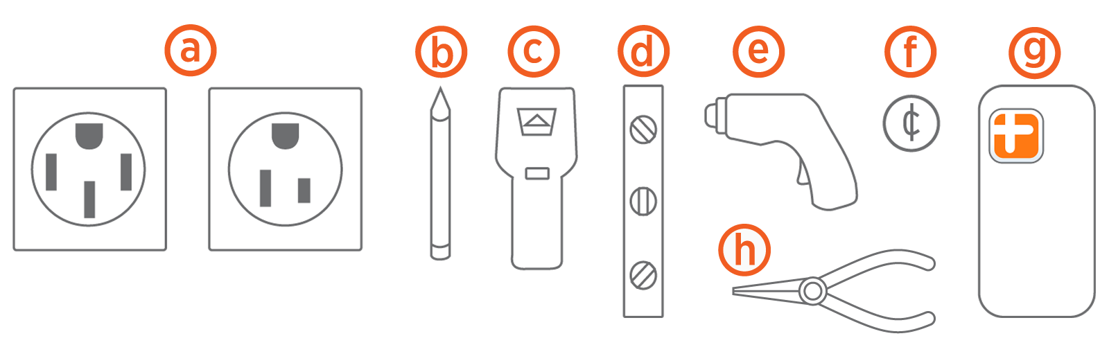
-
Electrical outlets - power sockets (optional)
-
Pencil
-
Stud finder
-
Level
-
Drill
-
Coin
-
Phone with app
-
Needle-nose pliers
Plan the Location
Before beginning work, check the site for appropriate mounting location and electrical capacity.
-
Ensure the homeowner has chosen an installation location that allows the charging cable to reach the car's charging port while still providing slack. Mount the charging station on a surface that can support the full weight of the charging station with the cord hanging from it. Follow the steps below to mount on a surface using the supplied screws. Ensure Wi-Fi
Wireless Fidelity signal is available.Outdoor installation requires hardwiring or an outdoor-rated, weather-resistant electrical outlet. In areas with frequent thunderstorms, add surge protection at the service panel. Ensure all power and ground connections, especially those at the breaker and bus bar, are clean and tight. Remove all oxide from all conductors and terminals before connecting the wiring.
-
Home Flex must be set to match the rating of the circuit as determined by the available panel capacity.
Home Flex is a continuous load device. The circuit must be rated for 125% of the maximum load.Consult all applicable codes for breaker and wire sizing requirements. The field-wiring terminal is rated to 105 °C (221 °F) and accepts a maximum of 16 mm2 (6 AWG
American Wire Gauge) wire.A junction box may be required when using breakers rated higher than 50 A.Supports the following amperages for circuit capacity Circuit Rating
Max Load
Estimated Range per Hour
Plug-in
Hardwire
70 A
50 A
37 miles/60 km
no
yes
60 A
48 A
36 miles/58 km
no
yes
50 A
40 A
30 miles/48 km
yes
yes
40 A
32 A
25 miles/40 km
yes
yes
30 A
24 A
18 miles/29 km
no
yes
20 A
16 A
12 miles/19 km
no
yes
In Canada, a plug-in installation is only allowed with a 50 A circuit.
-
For plug-in installation, determine the plug type purchased by the homeowner. It is either an Industrial Grade Outlet (NEMA
National Electrical Manufacturers Association 14‑50) or Industrial Grade Outlet (NEMA National Electrical Manufacturers Association 6-50) type plug. -
For a hardwired installation, determine if the desired circuit rating requires a hardwired circuit.
-
Ensure the electrical panel supports a 240 V dedicated circuit with a new, dedicated, non-GFCI
Ground-Fault Circuit Interrupter two-pole circuit breaker, in accordance with local codes and ordinances.If local codes require a GFCI Ground-Fault Circuit Interrupter breaker for plug-in installation, ChargePoint recommends a hardwire installation. We do not recommend using a GFCI Ground-Fault Circuit Interrupter breaker as the Home Flex has charging circuit interrupting device (CCID Charge Circuit Interrupting Device) protection. A GFCI Ground-Fault Circuit Interrupter breaker in the panel causes nuisance tripping. from the ground adjacent to the stud where the charging station will be mounted.")
-
For plug-in installations, the outlet should be located 500-600 mm or 0.5 m - 0.6 m (20-26 in) from the ground adjacent to the stud where the charging station will be mounted.
The input power cable is 0.3 m (12 in) or 300 mm (12 in) long (as per the National Electric Code for EV Electric Vehicle chargers). Ensure the outlet is installed close enough to the stud for the input power cable to plug in.
-
Follow all applicable codes and ordinances and pull a permit for completing the electrical work as required.
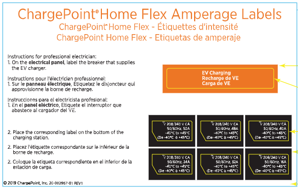
Apply the Electrical Ratings Label
To ensure compliance with inspection standards, apply the correct amperage label to both the charging station and the circuit breaker.
Required Item
ChargePoint Home Flex Amperage Label Sheet (included in box)
-
Find the sheet titled ChargePointHome Flex Amperage Labels in the packaging. It contains amperage labels in English, French, and Spanish for 16 A, 24 A, 32 A, 40 A, 48 A, and 50 A.
-
Confirm the amperage setting is configured during installation.
-
Peel the label that matches the configured amperage from the bottom of the sheet.
-
Locate the designated label area on the bottom edge of the charging station. Refer to the diagram below for exact placement.
_482x362.png)
-
Firmly press the label onto the surface to ensure adhesion.
-
Place a duplicate label on the breaker that supplies the EV
Electric Vehicle charging label in the electrical panel. This helps inspectors verify the amperage configuration. -
Ensure the label is clearly visible and legible.
Failure to apply the amperage label to the charging station and circuit breaker may result in failed inspection.
Wire the Circuit
To wire the circuit, complete the following steps:
-
Turn off the circuit breaker to the 240 V outlet.
-
Install a circuit:
-
For a 40 or 50 A plug-in installation, wire the circuit with the appropriate 6-50 or 14-50 outlet. Install the outlet with the ground facing up.
-
For a hardwired installation, provide a listed conduit with wiring to the bottom or rear 19 mm (3/4 in) knockout for AC input. Seal the unused knockout with the plug provided.
-
-
Affix the label with the appropriate rating to the circuit in the panel.
-
Ensure power is off to the circuit at the panel before proceeding.
Mount the Charging Station
Plug-in Installation
For a plug-in installation, complete the following steps:
-
Remove the faceplate and the wire cover from the charging station and set them aside.
-
Mark the center of the mounting location with a vertical line at a height between 1-1.1 m (39‑43 in) above the floor. This must be centered on a stud or other structurally suitable surface.
-
To determine the ideal mounting height of the charging station, connect the input power cable to the outlet.
If the front status light turns on when the charging station is plugged in, the circuit is not off. STOP IMMEDIATELY. Unplug the charging station and turn off the power to the outlet at the circuit breaker until the installation is complete.
 above the floor.")
-
Hold the station against the wall centered on the mark you just made.
Ensure that the input power cable has a slight curve and is not stretched.
-
Mark the two lower mounting holes through the holes in the station, then unplug the charging station and set aside.
-
Place the template on the wall, aligning the lower template holes with the two marks you made.
-
Mark the top mounting hole on the wall using the top hole in the template. All three marks should be on the vertical line you first made.
-
Remove the template from the wall.
-
Drill the three mounting holes on the marks using the included drill bit.
-
Use the driver bit to drive a screw into the top-most mounting hole, leaving a 3 mm (1/8 in) gap to hang the charging station on.
-
Hang the charging station on the screw using the top notch on the back.
Do not plug the charging station in yet. -
Drive the remaining two lag screws into the bottom mounting holes to secure the charging station.

 gap to hang the charging station on.")

For more information, see Install the Charging Cable section below.
Hardwired Installation
For hardwired installation, complete the following steps:
-
Remove the faceplate and the wire cover from the charging station and set them aside.
-
Mark the center of the mounting location with a vertical line at a height between 1.0-1.1 m (39-43 in) above the floor. This must be centered on a stud or other structurally suitable surface.
 above the floor.")
-
Hold the station against the wall, centered on the mark you just made. The top of the station should be approximately 1.3 m (50 in) above ground level.

-
Mark the two lower mounting holes through the holes in the station, set aside.
-
Place the template on the wall, aligning the lower template holes with the two marks you made.
-
Mark the top mounting hole on the wall using the top hole in the template. All three marks should be on the vertical line you first made.

-
Remove the template from the wall.
-
Drill the three mounting holes on the marks using the included drill bit.
-
Use the driver bit to drive a lag screw into the top-most mounting hole, leaving a 3 mm (1/8 in) gap to hang the charging station on. Keep the remaining two screws for later use.
 gap to hang the charging station on.")
-
If you bring power through the back of the station, remove the rear knockout plug and route the wires through before hanging the station.
If you are mounting on an exterior wall and bringing power through the rear knockout, apply sealant around the rear knockout to prevent water ingress. -
Hang the charging station on the screw using the top notch on the back.

-
Drive the remaining two lag screws into the bottom mounting holes to secure the charging station.

-
Ensure the service wiring can easily reach the connectors on the charging station’s input terminal block.
-
Tighten the locknut on the conduit fitting.
-
Strip each wire 12 mm (1/2 in).
-
Lift the white levers to open the terminal block. Fully insert the wires into the connectors on the left side of the terminal block with the ground wire in the center. Ensure to insert the wires in the correct order, where left terminal corresponds to Line 1 (L1), middle terminal is Ground (GND
Ground), and right terminal is Line 2 (L2). -
Press the levers down until they snap into place to secure the wires in the terminal block. Pull on the wires to ensure they are properly secured.
The levers will snap shut with great force. Keep fingers away from underneath the levers.

Install the Charging Cable
To install the charging cable, complete the following steps:
-
Turn off the circuit breaker to the 240 V outlet.
-
Remove the cable clip from the wire end of the cable, but do not discard it.
-
Lift the white levers to open the terminal block.
-
Insert the wires of the charging cable through the bottom hole of the charging station.
-
Match the green wire to the ground terminal on the left side of the output block.
-
Insert the ends of the wires into the corresponding holes, pushing the cables up until the silver conductors are no longer visible.
-
Press the three levers down until they snap into place.
The levers will snap shut with great force. Keep fingers from underneath the levers.
-
Insert the white plug into the connector towards the right of the terminal block.
-
Push up on the charge cable strain relief and slide the cable clip into the slot. This secures the cable in place.

-
Install the wire cover using a coin to lock it in place.

-
Locate the rating label on the bottom of the station. Apply the new rating label that matches the station's circuit.

-
Snap the faceplate onto the charging station.


Complete the Installation
To complete the installation, follow these steps:
-
Extend the cable to its full length to remove any twists or tension.
-
Drape the charging cable over the top of the charging station and dock the connector in its holster.
-
Ensure labels specifying circuit amperage are applied to the bottom of the charging station and to the circuit in the electrical panel.
-
Plug the charging station into the outlet (if applicable).
The images below represent a ChargePoint charging station integrated with two different adapters:-
J1772 cable
-
-
Restore power to the circuit at the electrical panel.
-
Watch to ensure the front status light glows yellow, then blinks white.
-
Return all packaging materials to the box and give the box to the homeowner.
Do not throw the guide away. Give the Quick Start Guide, the drill bit, the driver bit, and this Installation Guide to the homeowner.
.")
Access the Installer App
To access the installer application, complete the following steps:
-
Scan the QR
Quick Response code to download the app and sign up if necessary.Scan this QR
Quick Response code if you are using an Android device.Scan this QR
Quick Response code if you are using an iOS device.

-
Open the ChargePoint Installer app and log in.
-
Execute the following steps in the app:
-
Select Get Started and follow the app instructions.
-
Select the installation type.
-
Set the appropriate breaker settings.
-
Send a notification to the homeowner through mobile or email.
See Plan the Location section to determine the desired breaker rating (charging amperage).The homeowner will receive a notification that the installation is complete and to activate the charging station.
If you are unable to set the breaker rating via the ChargePoint Installer app, set the breaker rating via the homeowner's ChargePoint account using the ChargePoint app.
-
-
Activate the station to enable advanced features. The homeowner must follow these steps:
-
Refer to the Quick Start Guide.
The Quick Start Guide contains information that the homeowner needs to complete the charging station set up and activate it. -
Complete the charging station set up by downloading the ChargePoint application (distinct from the ChargePoint Installer app).
On the ChargePoint app, select Home Charger and choose Set Up. Depending on the app version, the Home Charger option may appear either under the menu icon or the home icon.
The electrician sets the maximum current by using the ChargePoint Installer app, but the homeowner must activate the station and complete the set up using the ChargePoint driver app.
-
Charging Station Status
The following table outlines the charging station status indicators and their corresponding meanings:
| Light | Status indicator |
|---|---|
|
|
Updating software or booting |
|
|
The charger needs to be set up in the app |
|
|
Ready to charge |
|
|
The charger is on a schedule. Plug in twice to charge immediately. |
|
|
Plugged in |
|
|
Currently charging |
|
|
Not connected to Wi-Fi Check Wi-Fi |
|
|
Something's wrong If the station is displaying an error, refer to our Troubleshooting Video. |

|
Wi-Fi
|


