CPIM1000 Integrated Meter Guide
To complete online training and become a certified installer, refer to ChargePoint University at: https://www.chargepoint.com/partners/training-certification.
For assistance, go to chargepoint.com/support and find your region’s technical support number.
CPIM1000 Integrated Meter
The CPIM1000 Integrated Meter is a multifunctional meter intended for use in the field of e-mobility. It uses a backlit LCD to communicate cumulative active energy and two LED pulse outputs to communicate energy steps. The CPIM1000 contains two AC meters, each with its own measuring unit measuring active energy. Accordingly, the display shows two cumulative energies and there is one pulse LED on each side, left and right. The complete device is supplied by the L1-N Input on the right side (top view). If this supply is not provided, the built-in relays remain open and a current flow is not possible.
Installation
The CPIM1000 Integrated Meter is built into CP6000 charging stations. The meter slides downward into the station pedestal housing and connects to a power plate. The meter connects to the power plate with plug-in connectors. User seals must be applied on the connection surface from the power plate to the meter. The left and right side output connectors with attached cables are plugged in and secured. User seals must also be applied on the output connector screws.
Metering Logic
CPIM1000 Integrated Meter current is measured using a current transformer and is transmitted through an A/D converter to a micro controller. Voltage is measured using a ground referenced measurement before it is transformed to a micro controller.
The sample rate is 3.90625 kHz and the energy update rate is 2x mains rate (100 Hz or EU, 120 Hz for US). At sample rate, V*I is accumulated, at energy update rate, the accumulated V*I values are converted to energy.
Fault Detection
In "meter mode" the operating faults have no affect on operations. The only faults that will prevent operation are those that occur on start up:
-
Failure to exit boot loader, generally caused by a bad code image loaded into flash. The LCD displays "-CHARGEPOIN+".
-
Initializing, caused by a MCP3914 failure. The unit will not transfer energy.
If these failures do occur, the meter must be disconnected from the main power supply by a certified ChargePoint technician. The hardware needs to be replaced.
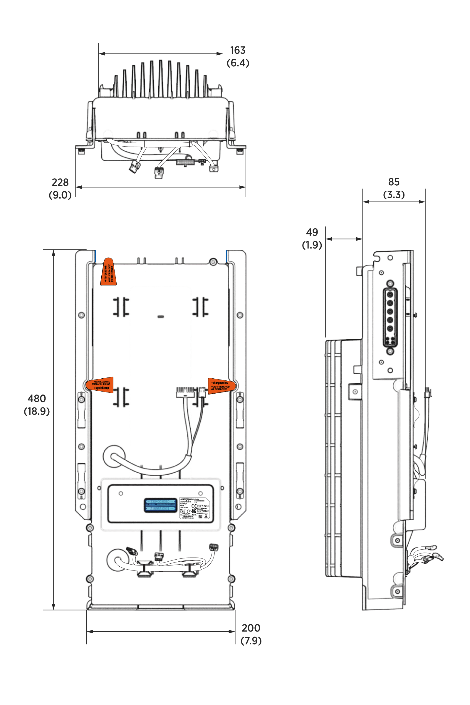
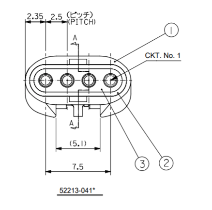
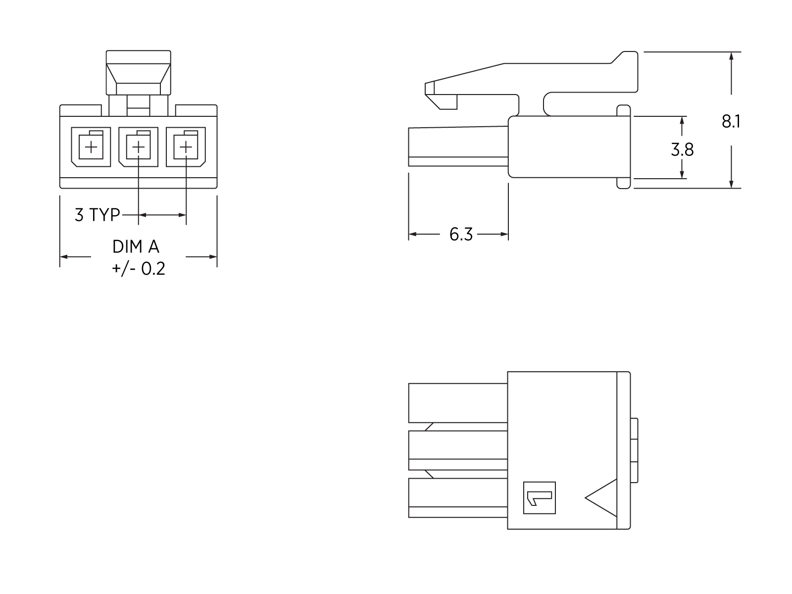
Dimensions
Images are not to scale. Measurements appear in metric units (mm) followed by imperial equivalents (inches).
Main Connectors
-
Left side output main connector
-
Right side output main connector
-
Backlit LCD display with pulse LEDs
-
Power input connector (includes two sets of main inputs)
-
CAN bus (The pins on the CAN bus are reserved)
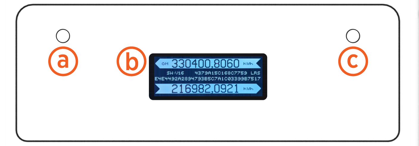
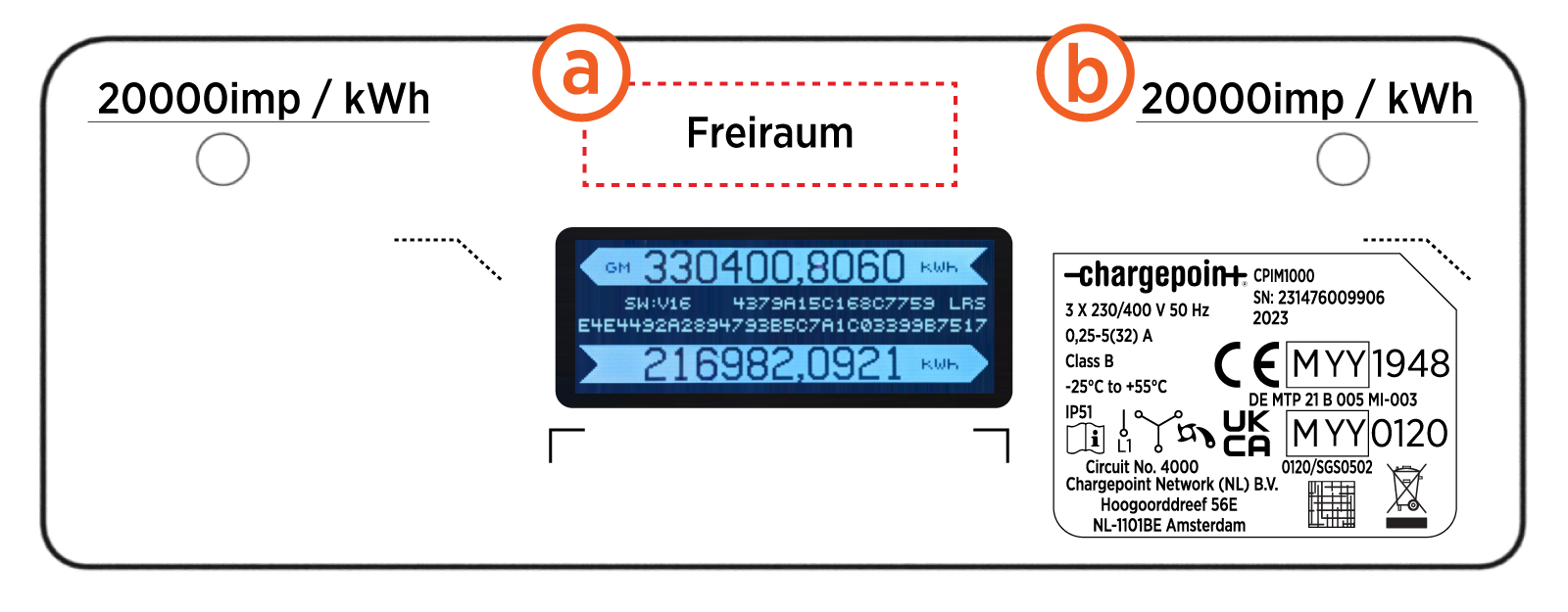
Integrated Meter Display
The LCD displays six digits before and four digits after the comma or decimal. The unit measure is kWh.
-
Left side impulse LED (20000 imp/kWh)
-
Backlit information LCD
-
Right side impulse LED (20000 imp/ kWh)
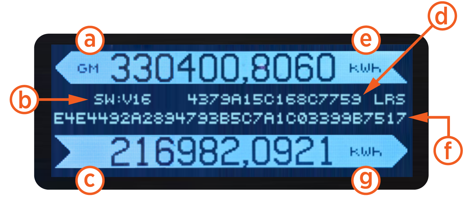
Backlit Information LCD
Common Information Readouts:
-
Left side flags
-
Overall software version
-
Right side flags
-
Overall software hash
Legally Relevant:
-
Left side cumulative energy reading
-
Legally Relevant Software (LRS) hash
-
Right side cumulative energy reading
MID Type Label
Circuit Number: 4000 : Standard: DIN 43856:1989-09
-
Space for calibration mark
-
Impulse constant
MID![]() Measuring Instruments Directive/MIR
Measuring Instruments Directive/MIR![]() Measuring Instruments Regulations label includes the following:
Measuring Instruments Regulations label includes the following: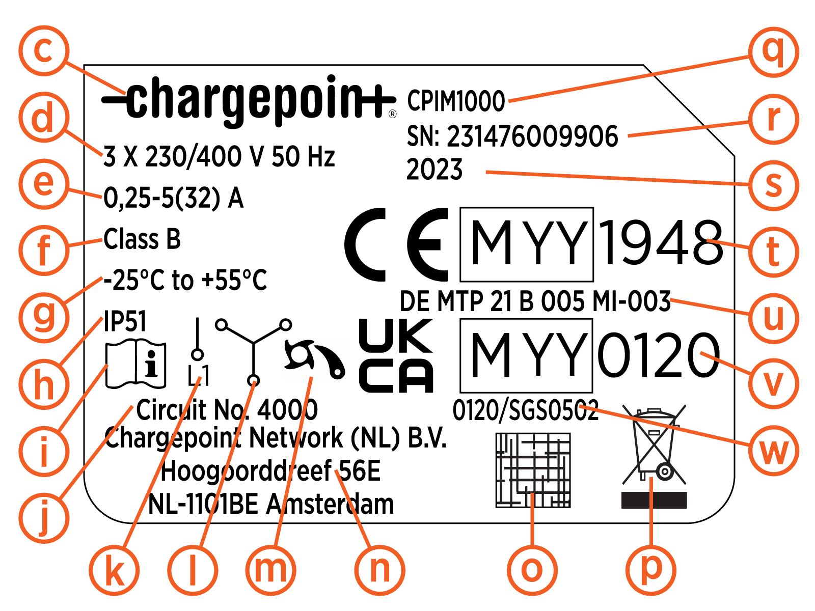
-
Customer logo
-
Reference voltage and frequency
-
Meter current values
-
Accuracy class
-
Temperature rating
-
IP rating
-
Existence of a manual
-
Number for circuit diagram
-
Symbol for one phase
-
Symbol for three phase
-
Symbol for escapement mechanism
-
Company address
-
QR
 Quick Response code with serial number
 -
WEEE waste symbol
-
Type number
-
Serial number
-
Year of manufacture
-
CE marking, MID
Measuring Instruments Directive metrology marking, number of the notified body for MID Measuring Instruments Directive -
MID
Measuring Instruments Directive certificate number -
UKCA marking, MIR
Measuring Instruments Regulations metrology marking, number of the notified body for MIR Measuring Instruments Regulations -
MIR
Measuring Instruments Regulations certificate number
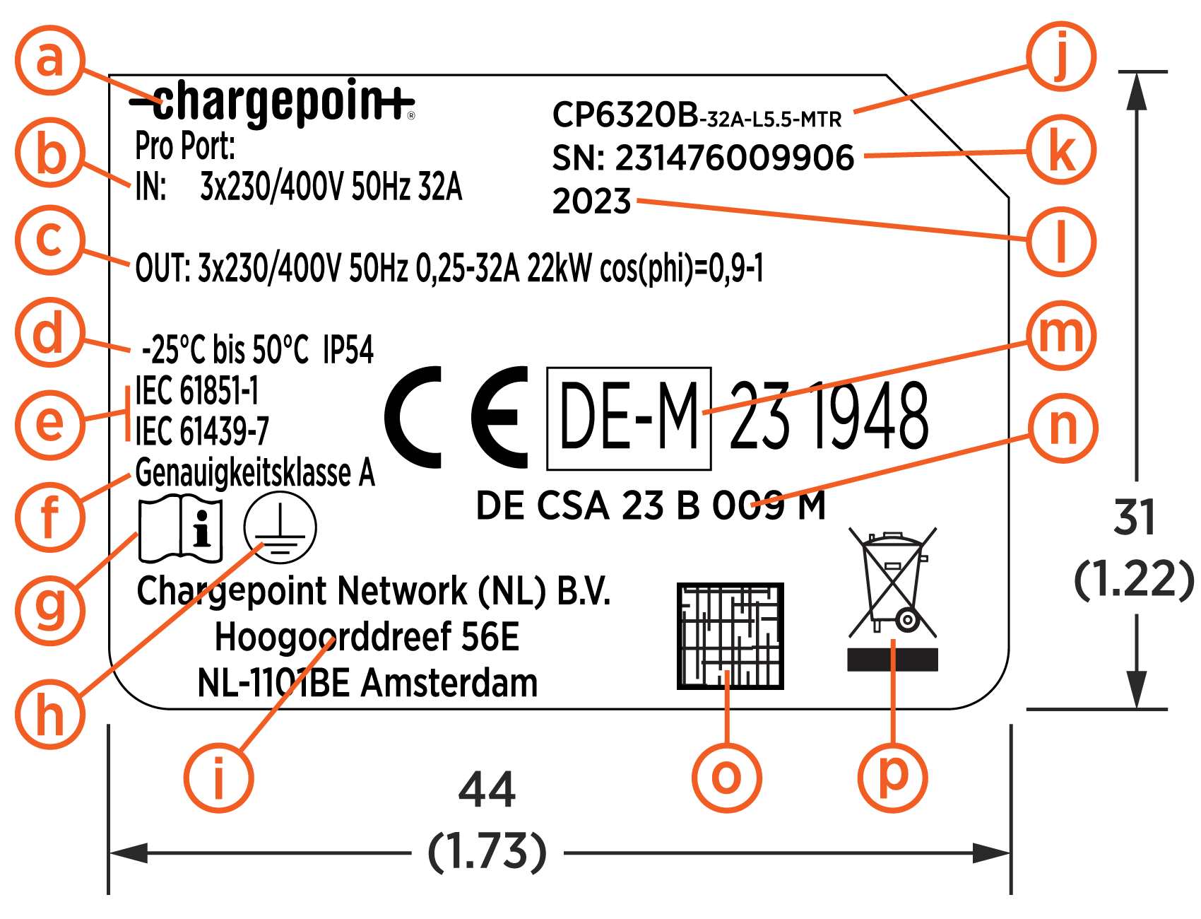
Three phase Eichrecht type labels include the following:
-
Manufacturer logo
-
Nominal electrical input parameters per port
-
Nominal electrical output parameters per port
-
Temperature rating /
IP rating -
Applicable standards
-
Accuracy class
-
Icon, documentation
-
Icon, class I equipment
-
Company address
-
Product type designation
-
Serial number
-
Year of manufacture
-
CE marking, Eichrecht metrology marking, number of the notified body for Eichrecht (Module D)
-
Certificate number
-
QR
Quick Response code with serial number -
WEEE waste symbol
See Eichrechtskonforme Typenbezeichnungen for more details.
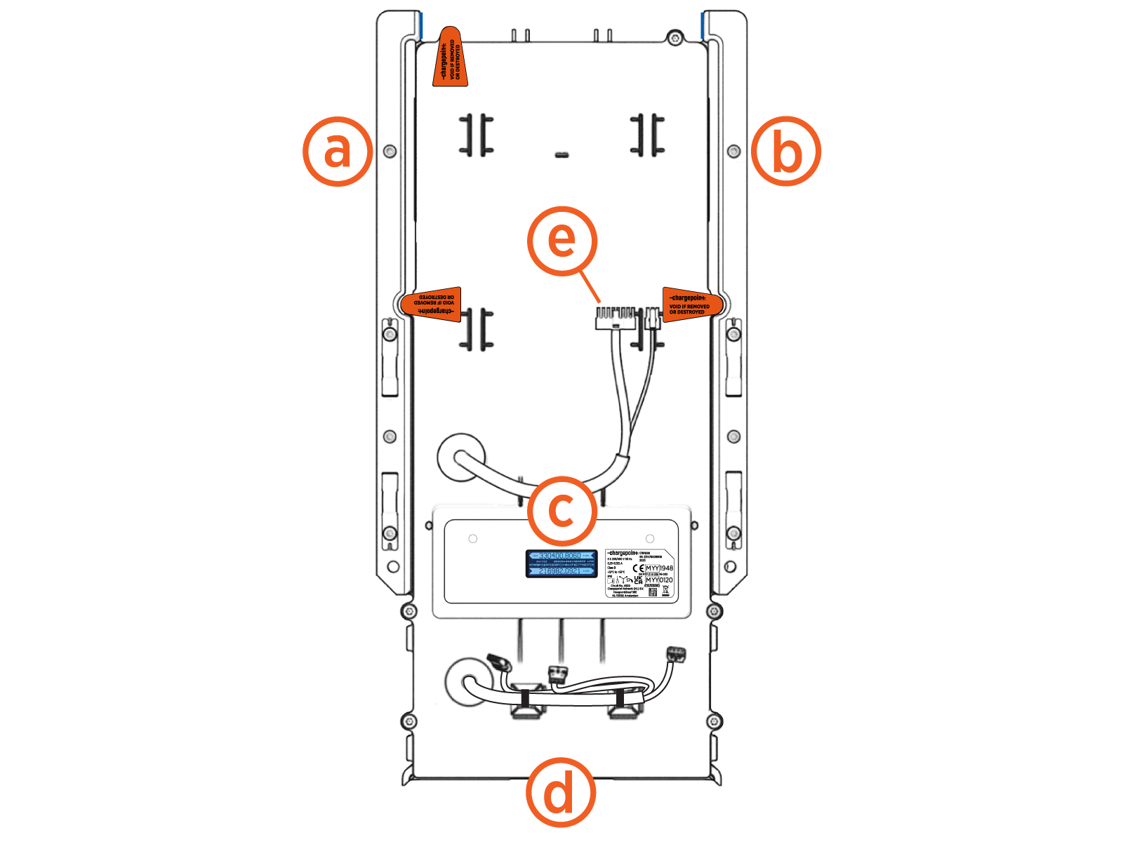
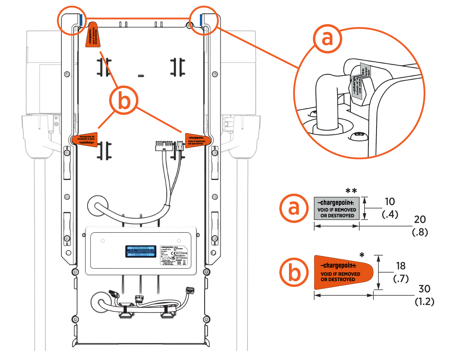
Data Protection
The energy data is computed and stored inside the STM32G4xx micro controller. The micro controller does not provide a mechanism for accessing this data other than via the meter firmware. The meter firmware does not provide a mechanism for updating the energy data from an external interface. The meter firmware can be updated during production or if the seal is removed, but a secure boot mechanism is used to prevent unsigned and unauthorized firmware.
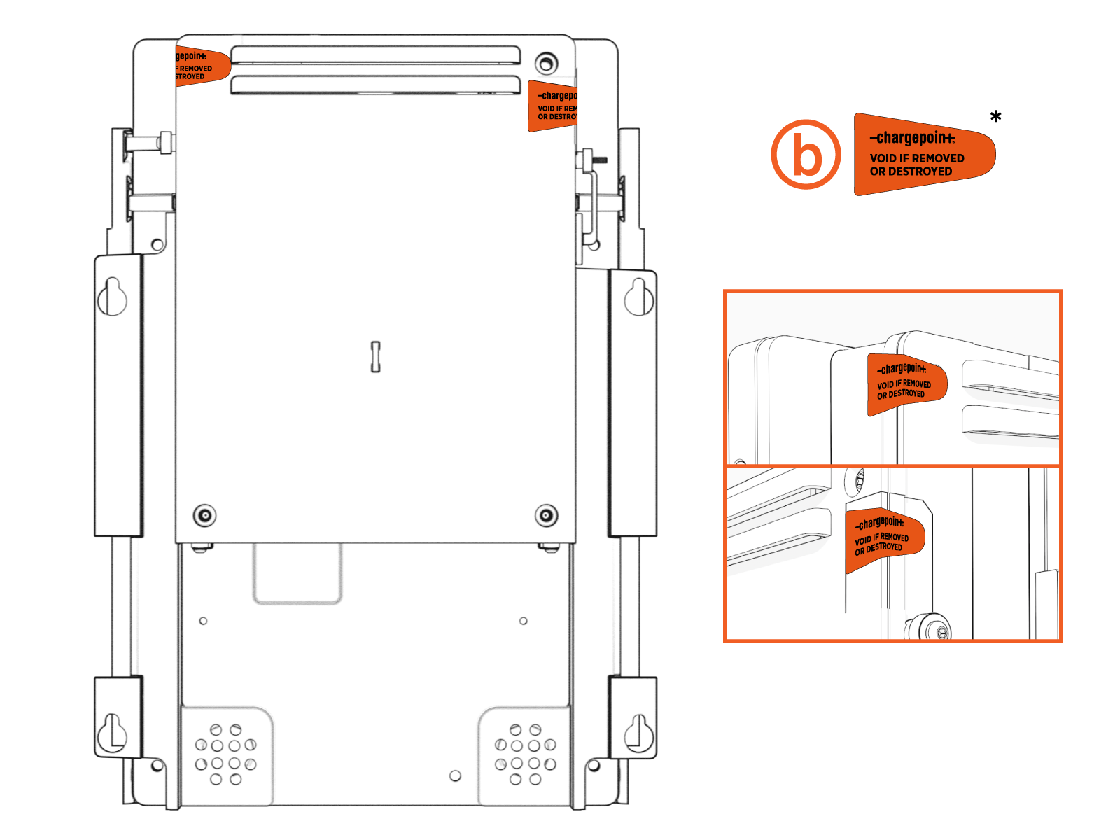
Components of the CP6000 have self destructive tamper proof labels applied by the manufacturer in several locations (a) and (b). Components of the CP6000 also have self destructive tamper proof labels applied by users in some locations (c) (optional).
* VOID IF REMOVED OR DESTROYED
** VOID IF REMOVED OR DESTROYED
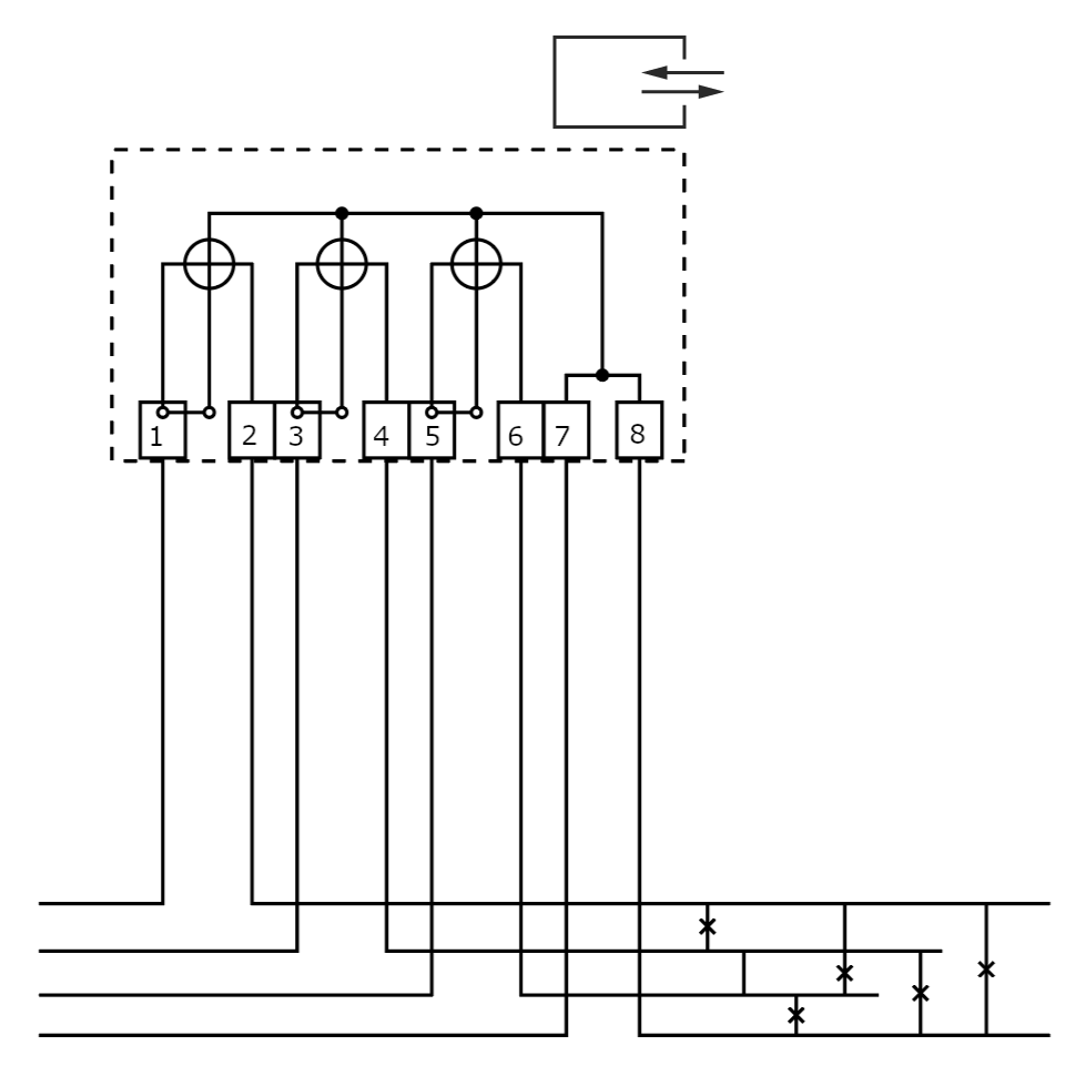
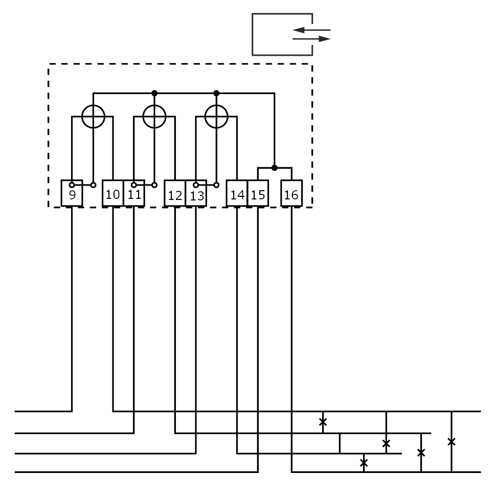
CPIM Meter Voltage and Current Circuitry
Description: Circuit number 4000 per standard DIN 43856:1989-09.
Left meter
Right meter
CPIM Interface Descriptions
The CPIM![]() ChargePoint Integrated Meter Integrated Meter includes LED, LCD, and CAN bus interfaces. This section describes the PCBA
ChargePoint Integrated Meter Integrated Meter includes LED, LCD, and CAN bus interfaces. This section describes the PCBA![]() Printed Circuit Board Assembly connector interfaces including interface type (protocol), connector type, pin assignment, and whether or not the connector is accessible externally or for test only,
Printed Circuit Board Assembly connector interfaces including interface type (protocol), connector type, pin assignment, and whether or not the connector is accessible externally or for test only,
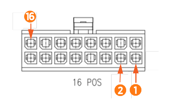
Integrated Meter Wiring Diagram
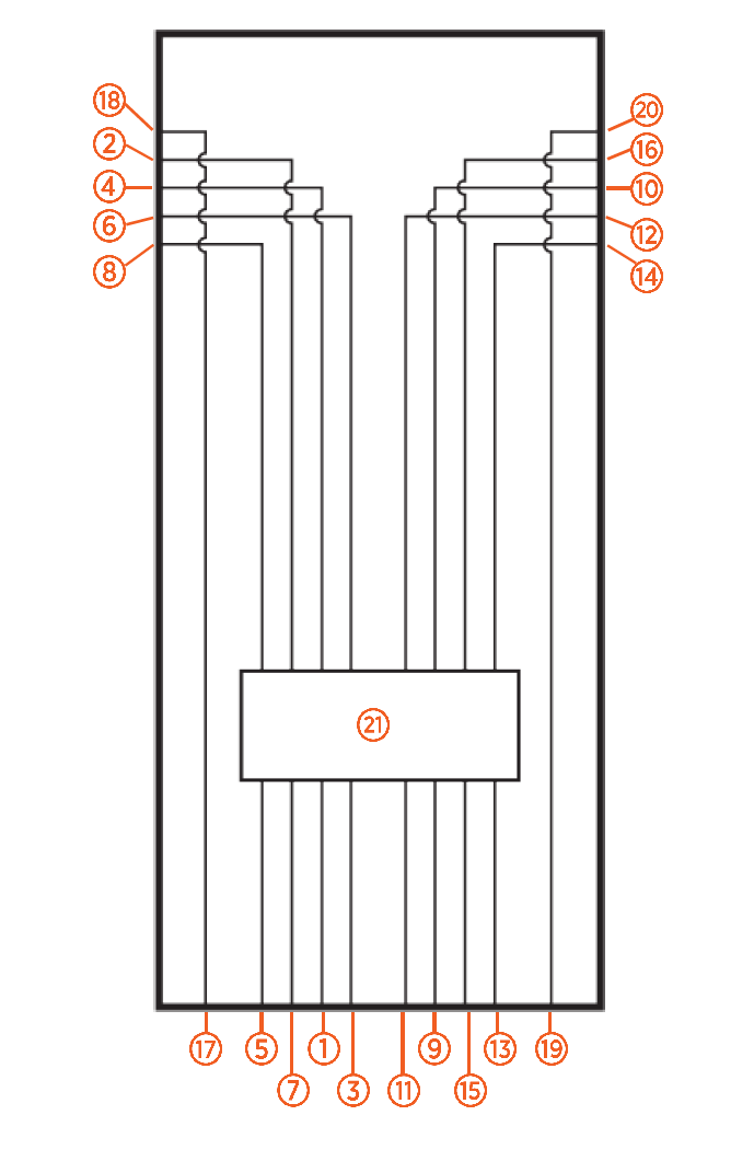
(1) L1 input - Left
(2) L1 output - Left
(3) L2 input - Left
(4) L2 output - Left
(5) L3 input - Left
(6) L3 output - Left
(7) Neutral input - Left
(8) Neutral output - Left
(9) L1 input - Right
(10) L1 output - Right
(11) L2 input - Right
(12) L2 output - Right
(13) L3 input - Right
(14) L3 output - Right
(15) Neutral input - Right
(16) Neutral output - Right
(17) PE input - Left
(18) PE output - Left
(19) PE input - Right
(20) PE output - Right
(21) Relays
Holster Connectors
|
Pin P1R (Right) |
Destination |
Signal Name |
Description |
|---|---|---|---|
|
1 |
AC, P1 14 |
MTR_RIGHT_DRV2 |
Motor drive output (+13.5V or -13.5V) |
|
2 |
AC, P1 13 |
MTR_LEFT_DRV2_RIGHT_DRV1 |
Motor drive output (+13.5V or -13.5V) |
|
3 |
AC, P1 8 |
MTR_RIGHT_SNS |
Motor sense feedback (digital) |
|
4 |
AC, P1 18 |
Motor sense feedback (digital) GND |
|
Pin P1L (Left) |
Destination |
Signal Name |
Description |
|---|---|---|---|
|
1 |
AC, P1 11 |
MTR_LEFT_DRV2 |
Motor drive output (+13.5V or -13.5V) |
|
2 |
AC, P1 12 |
MTR_LEFT_DRV2_RIGHT_DRV1 |
Motor drive output (+13.5V or -13.5V) |
|
3 |
AC, P1 7 |
MTR_LEFT_SNS |
Motor sense feedback (digital) |
|
4 |
AC, P1 6 |
Motor sense feedback (digital) GND |
|
Pin P2 (Led) |
Destination |
Signal Name |
Description |
|---|---|---|---|
|
1 |
AC, P1 15 |
LED_DOWNLIGHT_DRV |
White LED drive output (13.5V) |
|
2 |
AC, P1 16 |
LED_LEFT_EVIDENT |
Red LED drive output (3.3V) |
|
3 |
AC, P1 17 |
LED_RIGHT_EVIDENT |
Red LED drive output (3.3V) |
|
4 |
AC, P1 19 |
LED drive reference GND |
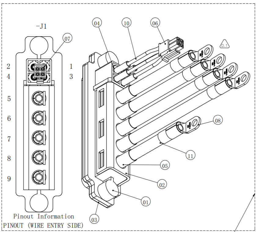
SEVB Signal Cable Connector (J1)
|
Pin |
Signal |
Description |
|---|---|---|
|
1 |
No connect |
|
|
2 |
+48 return |
Connected to Ground inside meter |
|
3 |
Pilot |
1kHz PWM input/output for EVSE |
|
4 |
+48 V |
48 V power supply output |
|
5 |
L3 |
Phase 3 |
|
6 |
L2 |
Phase 2 |
|
7 |
L1 |
Phase 1 |
|
8 |
Neutral |
Neutral |
|
9 |
Ground |
|
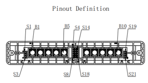
Power Plate - Blindmate (J7)
|
Pin |
Signal |
Description |
|---|---|---|
|
S1, S2, S3 |
MOV GND |
Left side SPD (Surge Protective Device) disconnect. Connect to GND |
|
S4, S5 |
LEFT TEMP |
Left power path external temperature sensor input. Connect thermistor between S4 and S5. |
|
S6, S7 |
RIGHT TEMP |
Right power path external temperature sensor input. Connect thermistor between S6 and S7. |
|
S8 |
Spare |
No connection |
|
S9, S10 |
AMBIENT TEMP |
Ambient external temperature sensor input. Connect thermistor between S9 and S10. |
|
S11 |
ID 1 |
External strapping pin to select operating region. ID1 shorted to GND |
|
S12 |
ID 2 |
External strapping pin to select operating region. ID2 shorted to GND |
|
S13 |
GROUND |
Ground internally shorted to B1, B10, and heatsink. |
|
S14 |
SHUNT LEFT |
External shunt trip connection for safety function. Connect left side RCCB |
|
S15 |
+48 V SHUNT LEFT |
External shunt trip connection for safety function. Connect left side RCCB |
|
S16 |
SHUNT RIGHT |
External shunt trip connection for safety function. Connect right side RCCB |
|
S17 |
+48 V SHUNT RIGHT |
External shunt trip connection for safety function. Connect right side RCCB |
|
S18 |
Spare |
No connection |
|
Pin |
Signal |
Description |
|---|---|---|
|
S19, S20, S21 |
MOV GND |
Right side SPD (Surge Protective Device) disconnect. Connect to GND |
|
B1 |
Mains earth/ground connection |
|
|
B2 |
LEFT AC C |
Left side line 3 input. |
|
B3 |
LEFT AC D |
Left side neutral input. |
|
B4 |
LEFT AC A |
Left side line 1 input. |
|
B5 |
LEFT AC B |
Left side line 2 input. |
|
B6 |
RIGHT AC B |
Right side line 3 input. |
|
B7 |
RIGHT AC A |
Right side line neutral input. |
|
B8 |
RIGHT AC D |
Right side line 1 input. |
|
B9 |
RIGHT AC C |
Right side line 2 input. |
|
B10 |
Mains earth/ground connection |
UCB Connectors
|
Pin197-08 |
Destination |
Signal Name |
Description |
|---|---|---|---|
|
1 |
AC, J1 2 |
Ground |
Ground output to auxiliary device. |
|
2 |
NC |
|
|
|
3 |
AC, J1 1 |
48 V power supply output to aux device |
|
Pin197-02 |
Destination |
Signal Name |
Description |
|---|---|---|---|
|
1 |
NC |
|
|
|
2 |
NC |
|
|
|
3 |
NC |
|
|
|
4 |
NC |
|
|
|
5 |
NC |
|
|
|
6 |
NC |
|
|
|
7 |
NC |
|
|
|
8 |
NC |
|
|
|
9 |
NC |
|
|
|
10 |
AC, P1 20 |
Can High |
Can bus for inter-communication. |
|
11 |
AC, P1 10 |
Can Low |
Can bus for inter-communication. |
|
12 |
NC |
|
|
|
13 |
NC |
|
|
|
14 |
NC |
|
|
|
15 |
NC |
|
|
|
15 |
NC |
|
|
Technical Specifications
CPIM1000 Integrated Meter complies with the following standards:
|
EN 50470-1:2006 |
|
EN 50470-3:2006 |
|
REA 6-A |
|
PTB-A 50.7 |
General Features
|
Connectors |
See "Input Connectors" on page 4 and "Input Connectors" on page 4 |
|
Protection grade |
IP51 |
Environmental Specifications
|
Power |
Self-powered (via measured voltage) |
|---|---|
|
Consumption |
<3 W, <10 VA (per port, multifunctional meter) |
|
Ist |
0.02 A |
|
Imin |
0.25 A |
|
Itr |
0.5 A |
|
Iref |
5 A |
|
Imax |
32 A |
|
Uref |
3 phase 230/400V AC or 1 phase 230V AC 400V AC phase-to-phase 230V AC phase-neutral, neutral connection mandatory |
|
Fref |
50 Hz |
|
Accuracy class |
Active energy: Class B (EN50470-3) |
Additional Environmental Specifications
|
Working temperature |
-25o C to 55o C Note: LCD performance degraded at <-10o C |
|
Storage temperature |
-40o C to 80o C |
|
Mechanical environment |
Class M1 - 2014/32/EU - Measuring Instrument Directive Class M1 - UK SI2016 No. 1153 - Measuring Instruments Regulations |
|
Electromagnetic environment |
Class E2 |
|
Application field |
Indoor meter |
|
Electrical protection |
Class I |
|
Storage and operating humidity |
5% - 95% RH at 50o C, non-condensing for up to two years |
LED Specifications
|
Pulse weight |
20000 imp / kWh |
|
Color |
Red |
Output Specifications
|
Pulse output |
Proportionate to measured active energy (EN62052-31) |
Minimum Number of Pulses for Repeatability Testing (per EN 50470-3)
|
Imin |
5 |
|
Itr |
15 |
|
Iref |
100 |
|
Imax |
300 |
