Civil and Mechanical Design
The following table provides gross weights for CPF50 station bundles, including packaging, to support accurate site planning and footing calculations. These values are based on complete SKU![]() Stock Keeping Unit configurations and are intended for use by project designers and installers.
Stock Keeping Unit configurations and are intended for use by project designers and installers.
|
Component |
Weight (lbs) |
|---|---|
|
CPF50-K-GW-LTE |
8.16 kg (18 lbs) |
|
CPF50-L18-WALLMNT-CMK6-GW-USA |
31.2 kg (69 lbs) |
| CPF50-L18-PEDMNT-CMK6-GW-USA | 43 kg (95 lbs) |
| CPF50-L18-PEDMNT-GW-USA | 22.6 kg (50 lbs) |
| CPF50-L18-PEDMNT-CMK6-Dual-GW-USA | 53 kg (117 lbs) |
| CPF50-L18-PEDMNT-Dual-GW-USA | 30.8 kg (68 lbs) |
| CPF50-L23-GW-USA | 8.16 kg (18 lbs) |
| CPF50-L23-WALLMNT-CMK8-GW-USA | 44.4 kg (98 lbs) |
| CPF50-L23-PEDMNT-CMK8-GW-USA | 56.2 kg (124 lbs) |
| CPF50-L23-PEDMNT-GW-USA | 22.6 kg (50 lbs) |
| CPF50-L23-PEDMNT-CMK8-Dual-GW-USA | 66.2 kg (146 lbs) |
| CPF50-L23-PEDMNT-Dual-GW-USA | 30.8 kg (68 lbs) |
| CPF50-L23-GW-NACS |
8.16 kg (18 lbs) |
| CPF50-L23-PEDMNT-CMK8-Dual-GW-NACS |
66.2 kg (146 lbs) |
| CPF50-L23-PEDMNT-Dual-GW-NACS |
30.8 kg (68 lbs) |
| CPF50-L23-PEDMNT-GW-NACS |
22.6 kg (50 lbs) |
|
TBA - CPF50-L23-PEDMNT-GW |
TBA |
|
TBA - CPF50-L18-PEDMNT-GW |
TBA |
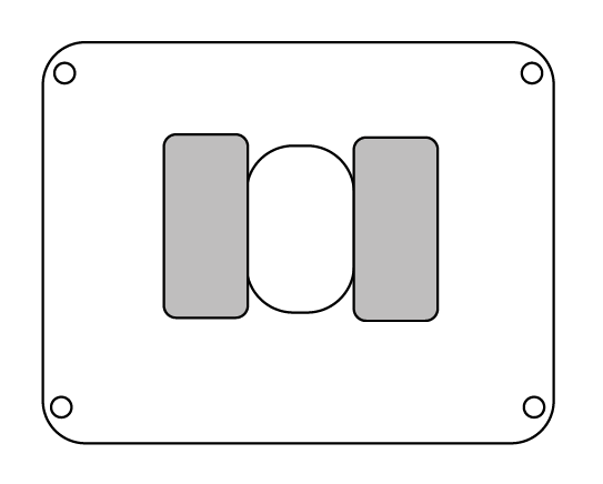
The ChargePoint CPF50 can be installed as a wall mount or a free-standing pedestal. Both options are suitable for indoor or outdoor use. Installation requires a licensed professional to ensure compliance with all safety and electrical codes. The stations are available in CMK![]() Cable Management Kit or non-CMK
Cable Management Kit or non-CMK![]() Cable Management Kit variants.
Cable Management Kit variants.
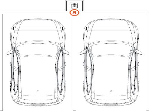
Wall mount Stations: The station is mounted on a flat wall using a back bracket. This is suitable for locations where there is a suitable wall, such as a garage or a building exterior.
Pedestal mount Stations: The station is mounted on a free-standing pedestal. This is ideal for locations like parking lots where there is no suitable wall available.
Wall Mount Stations
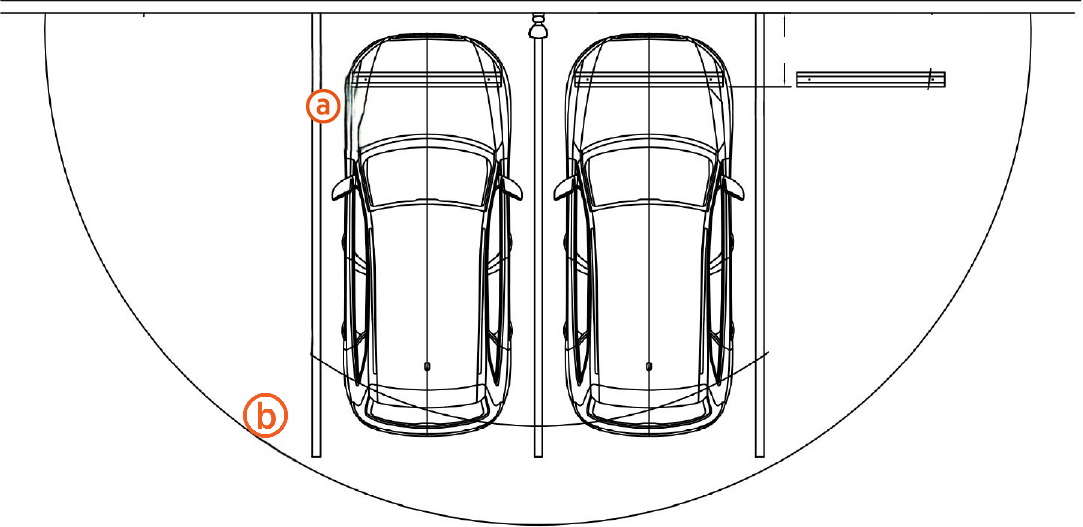
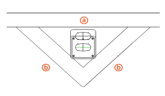
For wall mounted stations, the wall must be smooth, stable, and plumb. The minimum height of the wall must be 1250 mm (49 in). Place wheel stops (a) 900 mm (3 ft) from the wall. The arc shows the usable reach of the two charging cable lengths available, 5.5 m (18 ft) (b) and 7 m (23 ft) (c).
Pedestal Mount Stations
There are several single-sided or dual-sided pedestal configurations available with or without CMK![]() Cable Management Kit.
Cable Management Kit.
|
Feature |
Standard Pedestal |
Non-CMK |
|
CMK |
Yes |
No |
|
Single-sided |
Yes |
Yes |
|
Dual-sided |
Side-by-side NOTE: Stations face forward. |
Back-to-back NOTE: Stations face left and right. |
Refer to the following table for examples of standard CMK![]() Cable Management Kit and non-CMK
Cable Management Kit and non-CMK![]() Cable Management Kit pedestal configurations:
Cable Management Kit pedestal configurations:
|
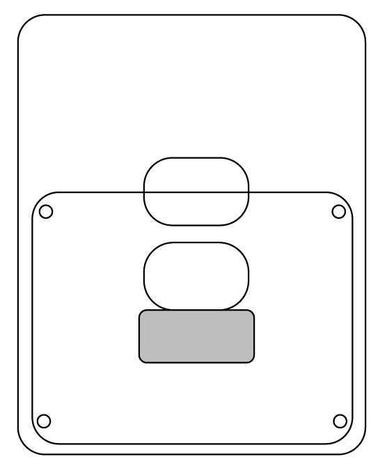
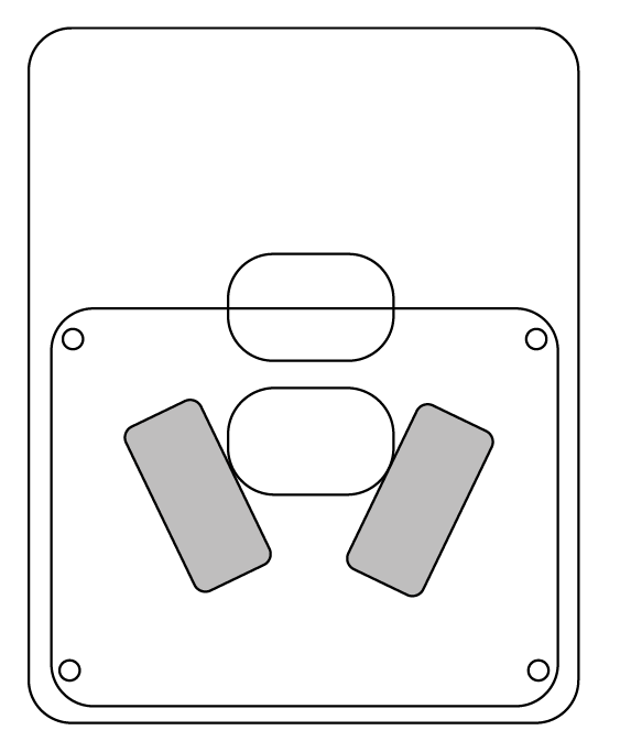
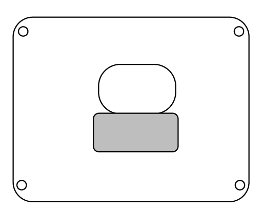
Configuration |
Single-Sided |
Dual-Sided |
|
Standard Pedestal NOTE: A standard pedestal is available in both CMK |
|
|
|
Non-CMK |
|
|
For newly poured pedestal mounted installations, the mounting surface must be smooth and cannot exceed a slope of 6 mm per 300 mm (0.25 in per ft). The concrete base must measure at least 600 mm (2 ft) on all sides. For installations in existing concrete, epoxy anchors can be used. Consult a civil engineer to ensure sufficient volume and strength of concrete.
There are three basic pedestal base designs:
-
In front of a curb (a) 900 mm (3 ft) x 2 (b)
Area: 0.42 m2 (4.5 ft2)
Volume: 0.26 m3 (9 ft3)
-
Behind a curb (a) in a planter or berm 600 mm (2 ft) on each side
Area: 0.37 m2 (4 ft2)
Volume: 0.23 m3 (8 ft3)
Use a retaining wall as needed to prevent dirt from accumulating on the pad.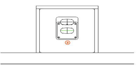
-
Two stations back to back, centered between four spaces 900 mm (3 ft) on each side
Area: 0.84 m2 (9 ft2)
Volume: 0.51 m3 (18 ft3)

Pedestal Configurations for Different Parking Arrangements
The pedestal base design can be configured in a variety of ways to serve different parking arrangements. Ensure a sufficient volume of concrete to provide anchoring for the charging station.
-
Place the station against the curb between spaces with wheel stops 900 mm (3 ft) from the front of each stall. The base of the charging station can be flush with the parking spaces or at curb level.
-
Place the station in a planter or berm between spaces with wheel stops 900 mm (3 ft) from the front of each stall or the curb (a).
- For configurations centered on four parking spaces, choose one of the following pedestal arrangements:
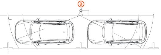
Place two stations back to back centered on four spaces with wheel stops 900 mm (3 ft) from the front of each stall. The base of the charging station can be flush with the parking spaces or at curb level (a).

Two dual-sided non-CMK
 Cable Management Kit pedestals: Place two non-CMK Cable Management Kit pedestals (a) back-to-back centered on four spaces. Rotate both pedestals 90 degrees so the stations face left and right. Place wheel stops 900 mm (3 ft) from the front of each stall. The base of the charging station can be flush with the parking spaces or at curb level.You can install either a single dual-sided non-CMK Cable Management Kit pedestal or two dual-sided non-CMK Cable Management Kit pedestals. The image below shows the two dual-sided non-CMK Cable Management Kit pedestals (a).
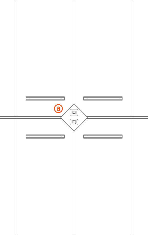
-
When placing a dual holster station centered on the right space, the charging cables can reach two vehicles. Place a wheel stop 1220 mm (4 ft) (a) from the center of the charging station.
Note the following details for this arrangement:
-
The arc shows the usable reach of the two charging cable lengths available: 5.5 m (18 ft) (b) and 7 m (23 ft) (c).
-
The 7 m (23 ft) cord option is recommended for this configuration.
-
The base of the charging station can be flush with the parking spaces or at curb level.
-
Ensure to install EV
Electric Vehicle Charging Station signs on both spaces.

-
-
Place a dual holster station centered between two parallel parking spaces, each 6 m (20 ft) long.
Place the station (a) 450 mm (18 in) from the curb. A 7 m (23 ft) charging cable is recommended.
-
Place a single holster station for a single parallel parking space 6 m (20 ft) long. Place the station (a) 450 mm (18 in) from the curb, and 1.8 m (6 ft) from the front of the parking space (b). This allows the cord to reach any part of the vehicle without blocking the curb side doors.

Ensure any site slopes, walls, or fencing do not trap water around the charging station installation site. The system is only built to withstand water to the height of the conduit stub-up.
For pedestal installations, the conduit stub-up must be a minimum of 230 mm (9 in) from any obstructions to the rear. This includes other charging stations. Check applicable codes for any additional clearance requirements.
Accessibility
To meet the accessibility requirements, the CPF50 charging cables are no more than 1220 mm (48 in) above ground and no more than 254 mm (10 in) away.
This complies with American Disability Act (ADA) requirements if the station is installed at grade. If your installation must comply with ADA standards, or the disability access regulations for other regions, consider this when designing the height of the pad or when planning a wall-mounted installation.
This complies with European disability requirements if the station is installed at grade. If your installation must comply with disability access regulations, consider this when designing the height of the pad or when planning a wall-mounted installation.
Also consider site design factors such as placement of bollards, wheel stops, or other vehicle obstacles when planning charging station access for disabled parking stalls. Check disability access regulations for guidance on the clearances needed for wheelchair access to charging cables and user interfaces.
