Mounting Options
This chapter details the steps for pedestal installation. Follow the instructions below to prepare the site and install the pedestal.
There are two types of pedestals:
-
Standard Pedestal: Continue to the next section.
-
Non-CMK
 Cable Management Kit Pedestal: Skip to Non-CMK Pedestal.
Standard Pedestal
Pedestal Mount Concrete Preparation
The CPF50 pedestal mount can be installed in one of the following ways:
-
Into the ground by casting new concrete.
-
Onto an existing concrete surface.
-
Onto a stacked parking platform.
Required Tools and Materials
The required kit components, required tools, and installation steps vary depending on the type of installation. This section provides basic guidelines for all approved installation types.
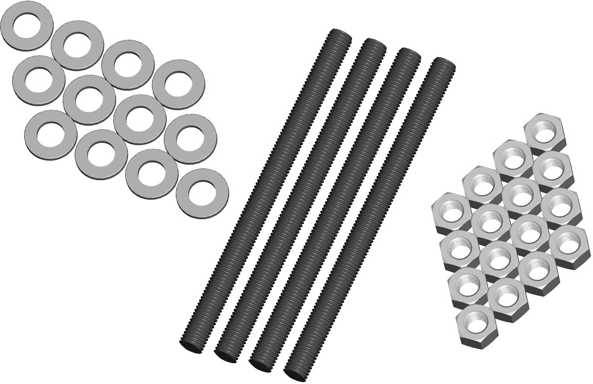
To install the CPF50 pedestal mount into the ground, you need the following components:
-
5/8” - 11 X 9” grade 55 bolts (4)
-
5/8” - 11 hex nuts (16)
-
5/8” washers (12)
-
These components can be purchased from ChargePoint by ordering a CPF50 Pedestal Mount Kit.
When installing onto an existing concrete surface, you only need 8 galvanized hex nuts and 8 galvanized washers. Additionally, required consumables are described below.
Install on New Concrete
Before casting new concrete, review the site for suitability to install a CPF50. The CPF50 requires space behind the conduit stub-up for the Cable Management Kit (CMK![]() Cable Management Kit), if applicable. To ensure adequate clearance, refer to the illustrations below and to the CPF50 Installation Template and the Mount Placement Guide included in the Concrete Mount Kit.
Cable Management Kit), if applicable. To ensure adequate clearance, refer to the illustrations below and to the CPF50 Installation Template and the Mount Placement Guide included in the Concrete Mount Kit.
https://docs.chargepoint.com/ref-docs-sec/content/pdfs/2-ac/cpf50/cpf50_cmt-cmk.pdf
https://docs.chargepoint.com/ref-docs-sec/content/pdfs/2-ac/cpf50/cpf50_cmt-without-cmk.pdf
Ensure that the PDF version of the mounting template is accurate by printing at 100% scale on 11x17 paper and verifying at least one dimension.
The instructions are as follows:
-
The concrete block must measure at least 600 mm (2 ft) on all sides.
-
The bolt threads must extend 60 mm (2.4 in) above the concrete.
-
The conduit must not exceed a maximum of 45 mm (1.8 in) in diameter and extend 660 mm (2 ft) above the concrete.
-
The service wiring must extend 1.5 m (5 ft) above the concrete surface.
-
Refer to Install the Pedestal chapter in the CPF50 Installation Guide available at ChargePoint Product Reference Documentation for detailed instructions on how to install the pedestal mount.
Pre-Installation Steps
Before starting the installation, complete the following preparation steps to ensure proper setup:
-
Dig a hole with the minimum measurements of 600 mm (2 ft) x 600 mm (2 ft) x 600 mm (2 ft).
-
Ensure that the electrical cable and conduit has been installed in the correct location and that the appropriate circuit protection and metering is in place, following all local codes and regulations.
-
Ensure that enough power cable (approximately 1.8 m (5.9 ft)) is above the planned ground level to create a service loop. It can be trimmed back during installation as needed.
-
Create a base for the concrete as required by local codes and regulations.
-
Create a wooden version of the template.
-
Build a temporary frame to support the wooden template over the hole.
-
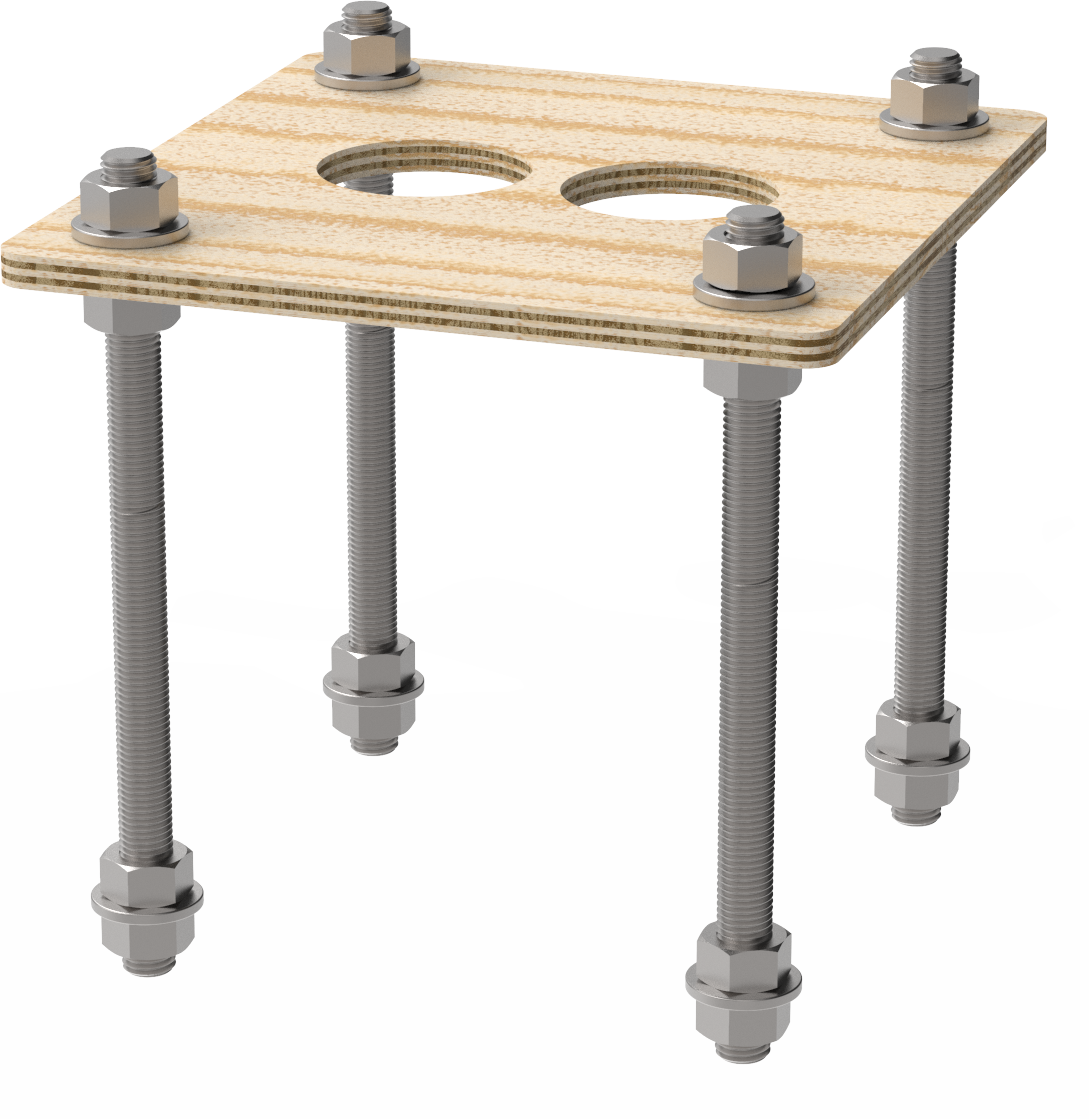
Before pouring the concrete pad, make sure that all pedestal mounting components are readily available at the installation site.
-
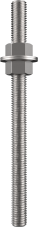
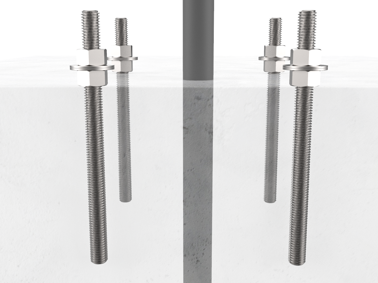
Install two nuts, with two washers captured between them, onto each of the three bolts, as illustrated. Lock them together so the lower end of the upper nut is located 165 mm (6.5 in) from the bottom of the bolt. This sets the length of the exposed threads.

-
Insert the four bolts through the wooden template. This ensures that the relative position of the bolts, and ensures that the flange of the pedestal fits over the bolts.
-
On the bottom end of each bolt, install a nut, a washer, and a nut. Lock the two nuts together so that the lower nut aligns to the bottom of the bolt. This provides retention for the bolt in the concrete.
Instructions
Follow these instructions after the preparation steps:
-
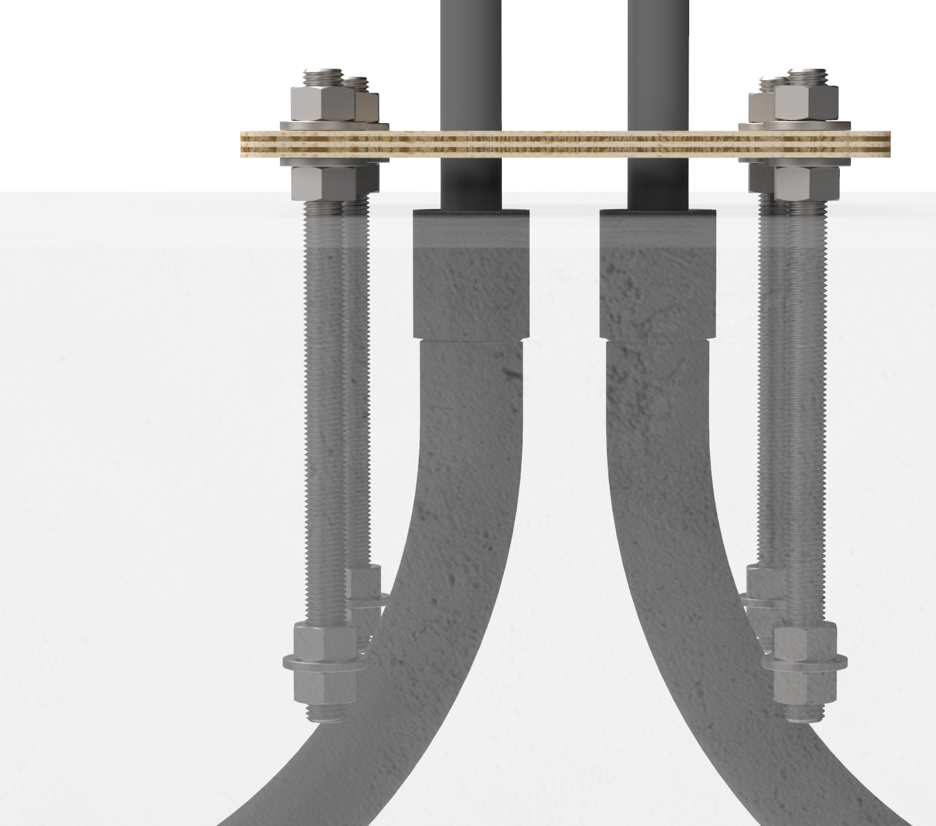
Pour the concrete into the hole you prepared.
-
Immediately after pouring the concrete, push the bolts into the concrete 165 mm (6.5 in) deep. You may need to slightly loosen the hexagon nuts to rotate the mounting bolts. Ensure correct alignment and that the top 60 mm (2.4 in) of the bolts remain exposed.
Rotate the bolts as you insert them. This allows the concrete to fully coat the threads of the bolts, reducing the amount of trapped air. -
Re-tighten the hexagon nuts to the template.
-
Remove any boards or shims supporting the mounting template. Leave the mounting template in place until the concrete is fully cured.
Post Concrete Cure
Follow these steps after the concrete has fully cured to ensure proper alignment and installation:
-
When the concrete is fully cured, remove the upper nut and the washer.
-
Adjust the remaining nuts and washers until about 35 mm (1.4 in) of bolt is exposed above each washer.
-
Use a spirit level and adjust the height of the nuts as required to ensure the four washers are completely level with each other.

-
When the concrete is fully set, remove the upper nuts and the washers to install the pedestal’s mounting post.
You are now ready to install the CPF50 pedestal mount charging station.
Install on an Existing Concrete
If installing on existing concrete, review the site for suitability to install a CPF50. The CPF50 requires space behind the power stub-up for the pedestal and (optional) CMK![]() Cable Management Kit. To ensure adequate space, refer to the CPF50 Installation Template included in the Concrete Mounting kit.
Cable Management Kit. To ensure adequate space, refer to the CPF50 Installation Template included in the Concrete Mounting kit.
The instructions are as follows:
-
Review the dimensions of the existing concrete slab. To safely mount a CPF50 charging station, the concrete must be at least 200 mm (8 in) thick. At this thickness, all CPF50 mounting bolts must be positioned at least 380 mm (15 in) from the front edge, at least 305 mm (12 in) from the side edges, and at least 150 mm (6 in) from the rear edge of the concrete slab.
-
If an existing charging station is already in place at the installation site, turn off all power to the station and disassemble according to the original manufacturer’s instructions. Cut away any existing bolts or non-power conduit stub-ups to ground level. Seal cut-away conduits at the slab end, and disconnect wiring at the other end.
-
Ensure you have adequate wiring. Service wiring for the CPF50 must extend 1.5 m (5 ft) above the platform’s surface.
-
ChargePoint recommends creating a rigid template based on the paper template to position the bolts.
Required Tools and Materials
Electric drill or hammer drill (12 mm or 1/2 in chuck may be required depending on drill bits used)
|
Quantity |
Description |
Purpose |
|---|---|---|
|
1 |
Epoxy adhesive for concrete such as Hilti RE-500. |
Fill drilled holes and secure anchor bolts. |
|
1 |
Electrical cleaning and maintenance aerosol, any angle spray duster, 235 ml (8 oz), such as McMaster #7437K35 |
Clean drilled holes. |
|
1 |
Slow spiral round-shank masonry drill bit, 25 mm (1 in) diameter, 12.5 mm (1/2 in) shank, 254 mm (10 in) drill depth, 305 mm (12 in) length overall, such as McMaster #2960A22 |
Drill 25 mm (1 in) holes in concrete. |
|
1 |
Drill bit for concrete embedded rebar, round 25 mm (1 in) bit size, 12.5 mm (1/2 in) shank diameter, 305 mm (12 in) length overall, such as McMaster #28655A25 |
Drill 25 mm (1 in) hole through rebar. |
|
1 |
Nylon loop handle brush, 25 mm (1 in) brush diameter, 76 mm (3 in) length brush, 216 mm (8-1/2 in) length overall, such as McMaster #7221T13 |
Clean drilled holes. |
|
1 |
Push-on round cap, fits 16 mm (5/8 in) - 17.5 mm (11/16 in) OD, 1/2 in inside height, pack of 100, such as McMaster #9753K47 |
Keeps the epoxy inside the drilled holes in situations where the slab is only 150 mm (6 in) deep. |
Instructions
After the concrete has fully cured, perform the following steps to ensure proper alignment and installation:
-
Install two nuts with two washers captured between them. Lock them together so the lower end of the nut is located 165 mm (6.5 in) from the bottom of the bolt. This sets the length of the exposed threads.
-
Use the Installation Template to mark the hole locations.
-
Remove the template and drill four 25 mm (1 in) diameter holes 165 mm (6.5 in) deep into the concrete. When locating the template, consider the station’s total footprint. For reference, a template is included in the Concrete Mounting kit.
-
Bolts must be parallel after installation. Therefore, ensure drill holes are plumb by using a bubble level to check the angle of the drill after drilling 25-38 mm (1 - 1.5 in).
-
If installing over existing buried conduit, position the center of the template around the conduit stub-up.
-
You may need two drill bits - one for the concrete (with the pilot) and another for the rebar (without the pilot). Always start the hole using the standard drill bit, then switch to the rebar drill bit only if drilling through rebar.
-
Remove all dust from inside the drilled holes using compressed air, a vacuum, and/or a brush.
-
If the concrete slab is only 165 mm (6.5 in) deep, insert a plug in each hole to keep the epoxy in place until it hardens. Place the plug over the long end of a bolt and use the bolt to push the plug to the bottom of the hole.
-
Fill each hole with epoxy to about 64-76 mm (2.5-3 in) below the top. Continue immediately to the next step because the epoxy sets within about eight minutes.
-
Inserting the threaded bolts displaces the epoxy, causing it to fill the holes to grade level. If the epoxy is below grade level, you can add more after the next step.
-
Place the Installation Template over the holes. This ensures the relative position of the bolts and that the flange of the pedestal fits over the bolts.
-
If needed, top up the holes with epoxy to grade level.
-
Allow the epoxy to cure according to manufacturer’s instructions before removing the top nuts and washer and before applying torque to the nuts.
Rotate the bolts as you insert them. This allows the epoxy to fully coat the threads of the bolts, reducing the amount of trapped air.
Post Concrete Cure
Follow these steps after the concrete has fully cured to ensure proper alignment and installation:
-
When the concrete is fully cured, remove the upper nut and the washer.
-
Adjust the remaining nuts and washers until about 35 mm (1.4 in) of bolt is exposed above each washer.
-
Use a spirit level and adjust the height of the nuts as required to ensure the four washers are completely level with each other.
-
When the concrete is fully set, remove the upper nuts and the washers to install the pedestal’s mounting post.
You are now ready to install the CPF50 pedestal mount.
Install on a Stacked Parking Platform
Before installing the CPF50 onto a stacked parking platform, ensure that the site is suitable. Every stacked parking platform is different. Therefore, instead of step-by-step instructions, ChargePoint provides the following guidelines:
-
The CPF50 requires at least 70 mm (2 3/4 in) between the rear edge of the mounting plate and the wall to allow adequate clearance for the CMK
Cable Management Kit. Refer to the CPF50 Mount Placement Guide for details. -
Before installing on the stacked parking platform, make sure that all pedestal mount components are readily available at the installation site.
-
Always check local codes to ensure compliance.
-
Ensure you have adequate wiring. Service wiring for the CPF50 must extend 1.5 m (5 ft) above the platform’s surface, like any other type of CPF50 installation.
-
-
Ensure that the pedestal is stable and does not move when the station is in use or when the platform is in motion.
Non-CMK Pedestal
The CPF50 pedestal mount can be installed one of the following ways:
-
Onto an existing concrete surface.
-
Onto a stacked parking platform.
Install on an Existing Concrete
Review the site for suitability to install a CPF50. The CPF50 requires space behind the power stub-up for the pedestal.
The instructions are as follows:
-
Review the dimensions of the existing concrete slab. To safely mount a CPF50 charging station, the concrete must be at least 150 mm (6 in) thick. At this thickness, all CPF50 mounting bolts must be positioned at least 380 mm (15 in) from the front edge, at least 305 mm (12 in) from the side edges, and at least 150 mm (6 in) from the rear edge of the concrete slab.
-
If an existing charging station is already in place at the installation site, turn off all power to the station and disassemble according to the original manufacturer’s instructions. Cut away any existing bolts or non-power conduit stub-ups to ground level. Seal cut-away conduits at the slab end, and disconnect wiring at the other end.
-
Ensure you have adequate wiring. Service wiring for the CPF50 must extend 1.3 m (51 in) above the platform’s surface.
-
ChargePoint recommends creating a rigid template based on the paper template to position the bolts.
-
The bolt position must be consistent with the bolt pattern template provided below.
Images are not to scale. Measurements appear in metric units (mm) followed by imperial equivalents (inches).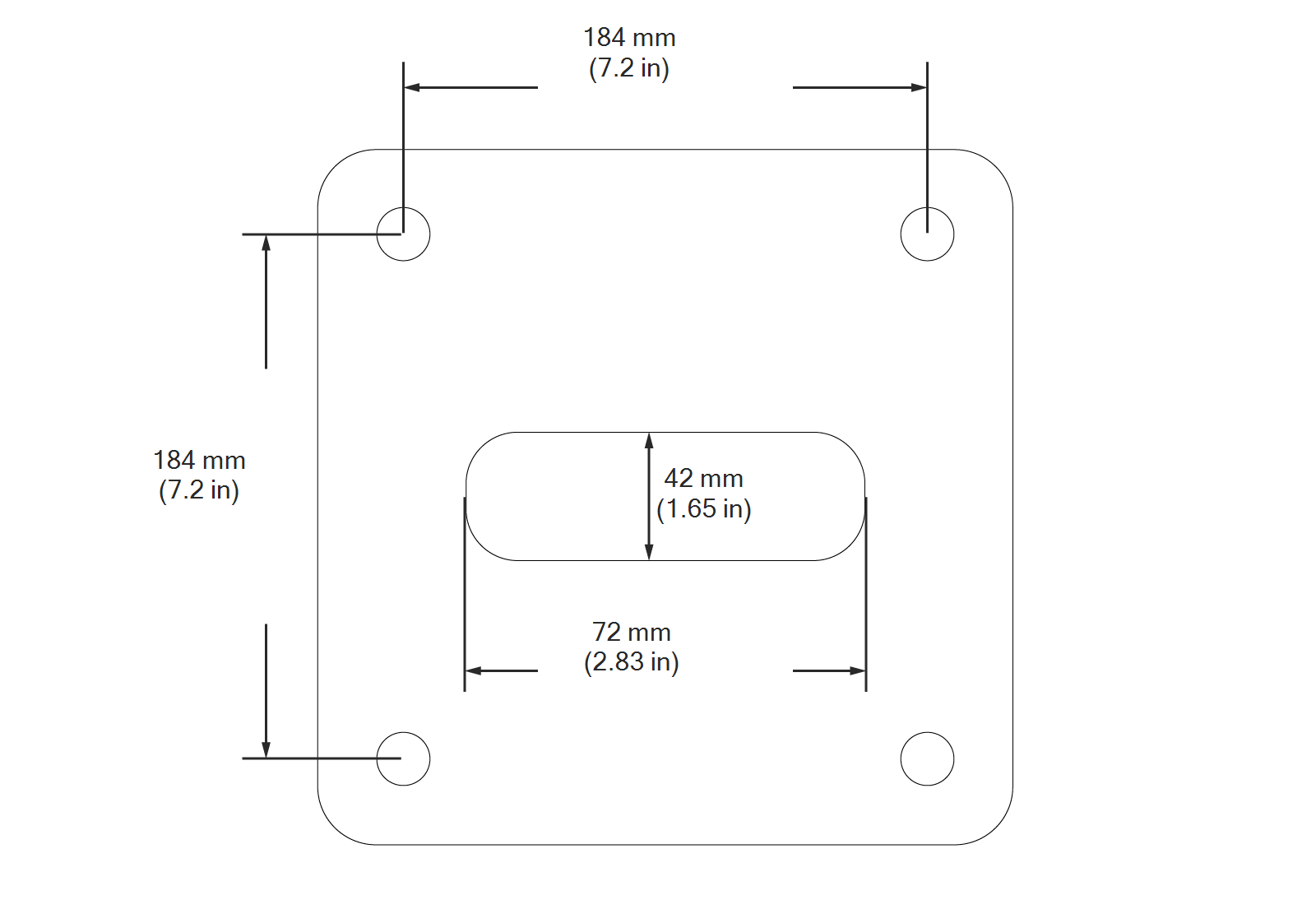
-
Conduit stub-up must extend approximately 0.3 m (1 ft) above the concrete surface.
-
The service wiring must extend 1.3 m (51 in) above the concrete surface.
Required Tools and Materials
Electric hammer drill with 12 mm (1/2 in) or larger chuck.
The following table lists and describes the tools that you will need.
|
Quantity |
Description |
Purpose |
|---|---|---|
|
1 |
Aerosol, any angle spray duster, 235 ml (8 oz) |
Clean drilled holes. (Compressed air or vacuum will also work.) |
|
1 |
Slow spiral round-shank masonry drill bit
|
Drill 16 mm (0.63 in) holes in concrete. (The holes must be at least 100 mm (4 in) deep.) |
|
1 |
Drill bit for concrete embedded rebar, round (if required)
|
Drill 16 mm (0.63 in) hole through rebar. |
Instructions
Perform the following steps to ensure proper alignment and installation:
-
Review the bolt hole pattern and mark the hole locations.
Images are not to scale. Measurements appear in metric units (mm) followed by imperial equivalents (inches).
-
Ensure that the conduit stub-up is at the center of the hole location.
-
Drill four 16 mm (0.625 in) diameter holes 100 mm (4 in) deep into the concrete.
Ensure the depth and diameter of each hole is correct.
-
Use compressed air, a vacuum, or a brush and remove all dust from the drilled holes.
-
Insert the bolts into the holes.
-
Use a hammer to tap the bolts until they protrude at least 30 mm (1-1/4 inches) above the surface.
Each bolt must extend at least 30 mm (1-1/4 inches) above the surface.
You are now ready to install the CPF50 pedestal mount.
Install on a Stacked Parking Platform
Before installing the CPF50 onto a stacked parking platform, ensure that the site is suitable. Every stacked parking platform is different. Therefore, instead of step-by-step instructions, ChargePoint provides the following guidelines:
-
Before installing on the stacked parking platform, make sure that all pedestal mount components are readily available at the installation site.
-
Always check local codes to ensure compliance.
-
Ensure you have adequate wiring. Service wiring for the CPF50 must extend 1.3 m (51 in) above the platform’s surface, like any other type of CPF50 installation.
-
Refer to Install the Pedestal chapter in the CPF50 Single or Dual-Sided Pedestal Installation Guide available at ChargePoint Product Reference Documentation for detailed instructions on how to install the pedestal mount. For stacked parking installations, it is acceptable to use a service cord (i.e. jacketed cable) without conduit inside the ChargePoint pedestal, provided the wiring is protected with appropriate bushings as it enters the pedestal.
-
Ensure that the pedestal is stable and does not move when the station is in use or when the platform is in motion.
