Electrical Design
The wall mount CPF50 installation uses surface mount wiring. The pedestal mount CPF50 installation requires service wiring installed underground. (If a pedestal mount installation requires surface run conduit, contact ChargePoint before beginning work to obtain an approved installation method.) Conduit and wire size are determined based on the length of runs from the electrical panel to the station location. Service wiring must be run through conduit to comply with local electrical codes. Consult national and local codes or a project engineer to determine the grade, quality, and size of the conduit or cable. The CPF50 Concrete Mount Kit accommodates service wiring through the flare, conduit, or locally appropriate wiring method.
Upstream Wiring
Charging stations are considered continuous load devices (EVs draw maximum load for long durations); therefore, electrical branch circuits must be sized at 125% of the load for North American installations, in accordance with National Electric Code (NEC![]() National Electric Code) requirements. (For other regions, refer to local code.) This means that for a maximum 50 A load at 208/240 V output to an electric vehicle, 65 or 70 A breakers are required.
National Electric Code) requirements. (For other regions, refer to local code.) This means that for a maximum 50 A load at 208/240 V output to an electric vehicle, 65 or 70 A breakers are required.
Wiring must be sized in accordance with NEC![]() National Electric Code code for continuous load devices. Typically, 16 mm2 or 10 mm2 (6 AWG
National Electric Code code for continuous load devices. Typically, 16 mm2 or 10 mm2 (6 AWG![]() American Wire Gauge or 8 AWG
American Wire Gauge or 8 AWG![]() American Wire Gauge) insulated electrical wire is used, depending upon the rating of the circuit and the distance between the electrical panel and the charging station. The terminal block accepts a maximum of 16 mm2 (6 AWG
American Wire Gauge) insulated electrical wire is used, depending upon the rating of the circuit and the distance between the electrical panel and the charging station. The terminal block accepts a maximum of 16 mm2 (6 AWG![]() American Wire Gauge).
American Wire Gauge).
When planning multiple EV![]() Electric Vehicle charging stations, it is best practice to separate non-continuous from continuous loads, with all branch circuits for EV
Electric Vehicle charging stations, it is best practice to separate non-continuous from continuous loads, with all branch circuits for EV![]() Electric Vehicle charging on a dedicated electrical panel assembly with adequate circuit breakers. When sizing new electrical panels dedicated for EV
Electric Vehicle charging on a dedicated electrical panel assembly with adequate circuit breakers. When sizing new electrical panels dedicated for EV![]() Electric Vehicle charging, all branch circuits must support continuous load, and the panel rating must be sized for at least 125% of the total load on each leg of a 3-phase panel.
Electric Vehicle charging, all branch circuits must support continuous load, and the panel rating must be sized for at least 125% of the total load on each leg of a 3-phase panel.
Conduit
The outside diameter of conduit must not exceed the sizes called out in the conduit layout drawing: 45 mm (1.8 in). Conduit stub-ups must not extend higher than 660 mm (26 in) above grade.
For wall mounted stations, flex conduit must be used to bring the wire to the station.
Wiring Requirements
For full product specifications, refer to the CPF50 Datasheet. Using that data, ensure that the installation location is equipped with service wiring that supports the CPF50’s power requirements:
-
AC conductors (L1, L2)
-
Ground conductor
When pulling electrical wiring for CPF50 pedestal mount, ensure at least 1.5 m (5 ft) of wire remains above grade.
When pulling electrical for wall mounted stations, the conduit and wire must be brought to the location where the stations will be mounted. Flex conduit may be used to bring the wire to the station. Wiring is usually brought in via the bottom of the CPF50. The CPF50 has a 21 mm (3/4 in trade size) knock-out in the bottom and the rear of the charging station.
Wiring Diagram
240 VAC Single Phase Panel

(1) Main Breaker
(2) Ground Bus
(3) L1
(4) L2
(5) Ground
(6) L1
(7) L2
(8) Input Terminal Block
(9) Output Terminal Block
(10) Local Service or Sub Panel
208 VAC Three Phase Panel
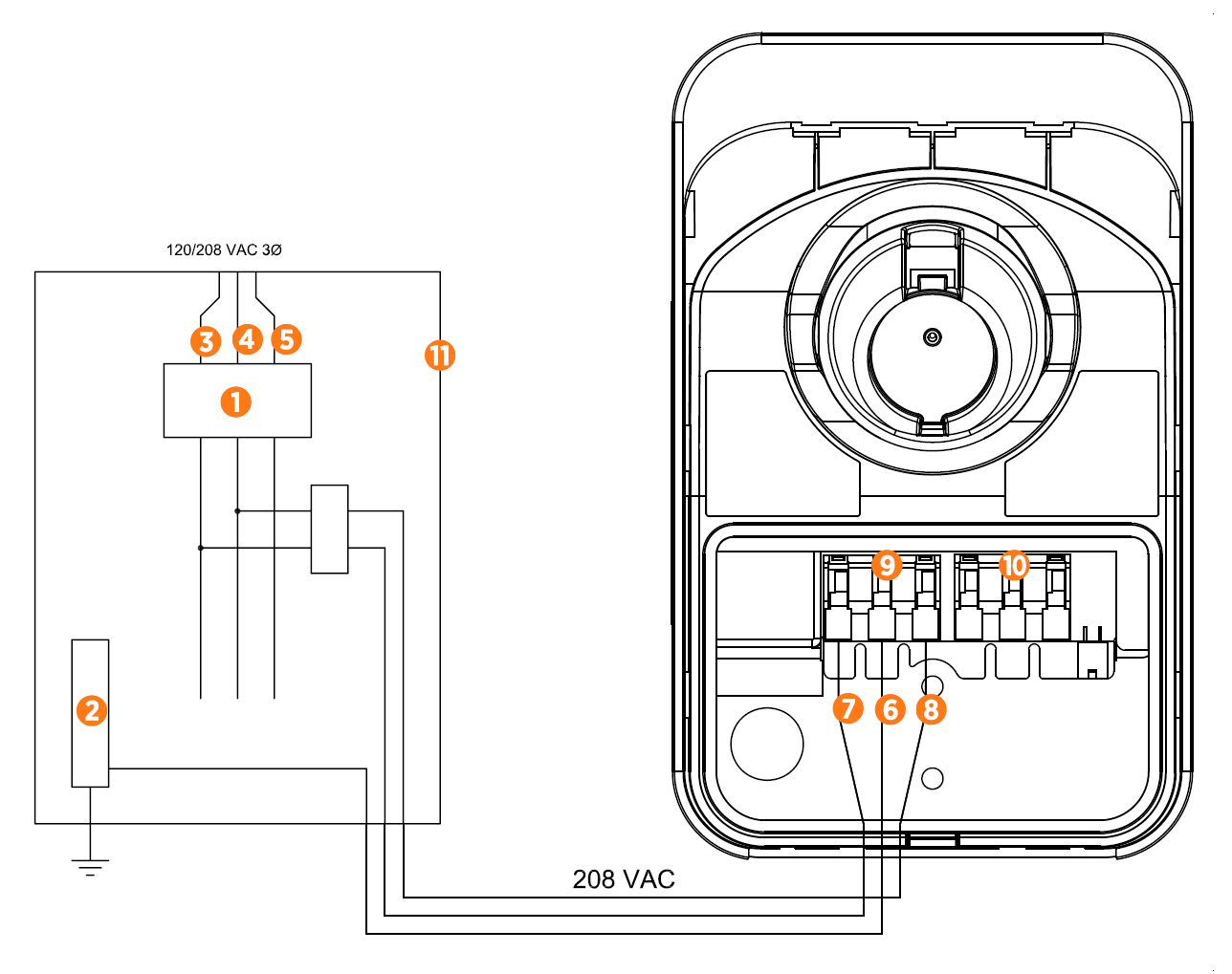
(1) Main Breaker
(2) Ground Bus
(3) L1
(4) L2
(5) L3
(6) Ground
(7) L1
(8) L2/N
(9) Input Terminal Block
(10) Output Terminal Block
(11) Local Service or Sub Panel
Grounding Requirements
The CPF50 must be connected to a grounded, metal, permanent wiring system. An equipment-grounding conductor must be run with circuit conductors and connected to an equipment-grounding terminal or lead on the CPF50.
A grounding conductor that complies with applicable codes must be grounded to earth at the service equipment or, when supplied by a separate system, at the supply transformer.
Ensure that a grounding conductor that complies with all applicable codes is properly grounded to earth at the service equipment or, when supplied by a separate system, at the supply transformer.
Neutral is not used to power the station but must be properly connected to ground, at the panel or transformer, to provide the necessary voltage reference relative to ground.
-
In a Wye system, connect the station to any two lines, as shown.
-
In a Delta system, connect the station to a center-tapped secondary only, where the center tap is bonded and the station is connected to the L1 and L3. This allows voltages to remain constant regardless of other loads that may be using the lines.
Connect to these Systems
The following configuration shows how the bonded neutral station connects to the system:
-
120/240 VAC, 10 Bonded Neutral Station is connected to L1 and L2 Neutral is not used
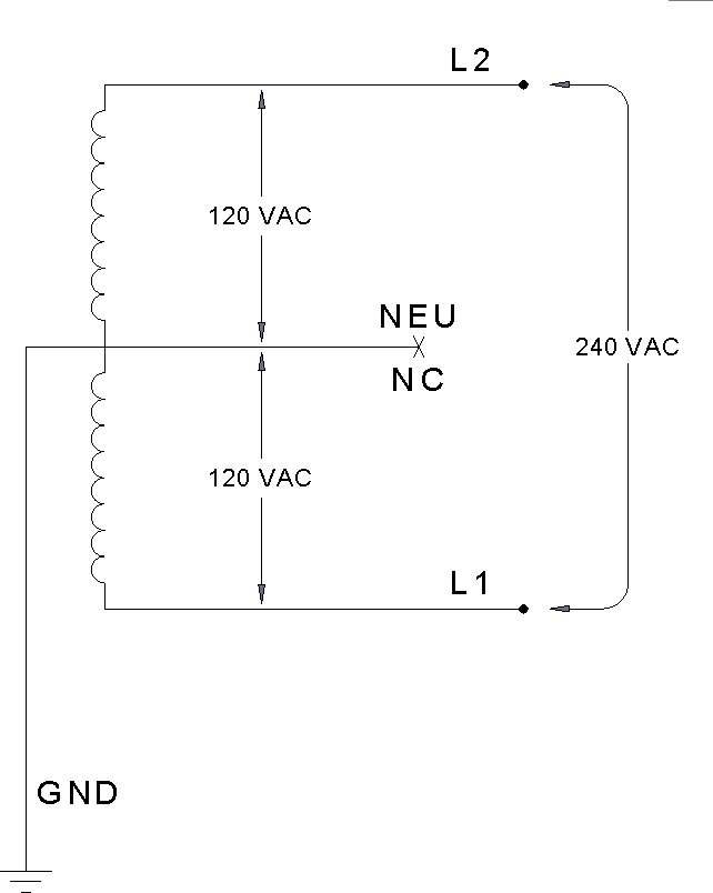
-
120/208 VAC, 30 Wye Bonded Neutral Station may be connected to any two lines Neutral is not used
-
120/240 VAC, 30 Delta Center tap grounded Bonded neutral
Station must be connected to L1 and L2 only Do not connect any part of the system to L3 Neutral is not used
Not recommended for new construction

Do Not Connect to these Systems
The following system configuration must not be used because it poses grounding and voltage risks:
-
120/208 VAC 3 phase Wye, ungrounded Floating neutral
Voltage of either line to ground is undetermined Neutral is not grounded

-
120/240 VAC 3 phase Delta, corner-grounded Voltage of any line is not 120 V nominal relative to ground
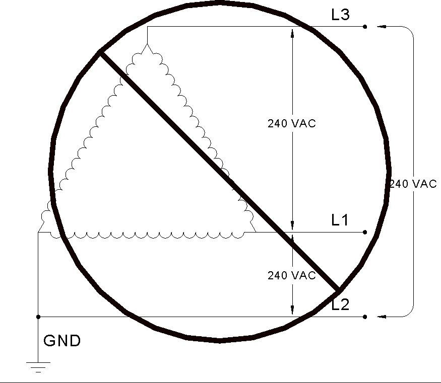
-
Any system where the center point of the AC power source is not grounded.
Plan for the Gateway (Optional)
The CPF50 charging station has its own cellular connection. Earlier models of CPF50 require that the ChargePoint Gateway is installed for cellular connectivity. To determine whether the CPF50 model has its own cellular connectivity, look for the label at the bottom of the station, which indicates the model name. A model name with CPF50-K will have a cellular modem, while a model name with CPF50 will require the ChargePoint Gateway for cellular connection. If the ChargePoint Gateway is required, each CPF50 must be installed within 45 m (150 ft) of the Gateway within line of sight.
The ChargePoint Gateway consists of a cellular modem for wide area networking and built-in Wi-Fi![]() Wireless Fidelity for local communications to and from the CPF50 charging stations. The Gateway should be located where cellular signal levels are optimal for LTE
Wireless Fidelity for local communications to and from the CPF50 charging stations. The Gateway should be located where cellular signal levels are optimal for LTE![]() Long Term Evolution. Each Gateway must be located within 150 feet line-of-sight to as many as nine CPF50 charging stations. Each CPF50 charging station has built-in Wi-Fi
Long Term Evolution. Each Gateway must be located within 150 feet line-of-sight to as many as nine CPF50 charging stations. Each CPF50 charging station has built-in Wi-Fi![]() Wireless Fidelity capability to communicate via the Gateway for ChargePoint network services.
Wireless Fidelity capability to communicate via the Gateway for ChargePoint network services.
The Gateway is a UL Class 2 device and requires less than four watts power (33 mA@120 V or 19 mA@208 V). ChargePoint recommends hardwire electrical termination to the power source for the Gateway.
The Gateway dimensions are 280 mm (11 in) wide by 340 mm (13 3/8 in) long by 137 mm (5 3/8 in) deep. The datasheet, installation guide, and mounting template are available at ChargePoint Product Reference Documentation.
