Verify Station Wiring and Voltage
To verify the station wiring, voltage readings and connection, follow these steps:
Tools Needed
|
|
Needle Nose Pliers |
|
T25 Security screwdriver |
|
|
Solenoid Voltage Meter (Wiggy) |
|
Digital Multi-Meter (DMM) |
|
|
Alligator clip leads or pass-through leads (optional) |
|
Power share jumper* NOTE: *not required for all stations |
|
|
Wire stripper |


Station Wiring Checks
-
With the station powered on:
Make note if the station shows as power shared under the station name in the top title bar of the display screen.
Power sharing No Power sharing 

-
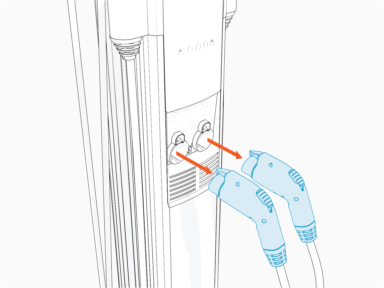
Remove the handles from the holsters.
- This can be done with a local driver or fleet card (tap if the station is sufficiently operational).
- You can also have the holsters released remotely if that's possible. For assistance, go to chargepoint.com/support and contact technical support using the appropriate region-specific number.
-
If neither of the above options are possible, you can manually release the handles from the holster by following below steps:
-
Before you begin, power off the station.
RISK OF SHOCK
Before performing any procedure, the technician must disconnect the power to the charging station at the service panel. Follow local code to de-energize the applicable circuit and lockout/tagout the upstream breaker before proceeding. Use a multimeter and check that the power is off. Keep power off for the circuit until all cover panels are correctly reinstalled and the work is complete.
FAILURE TO FOLLOW THESE INSTRUCTIONS CAN RESULT IN SERIOUS INJURY, LOSS OF LIFE, OR PROPERTY DAMAGE. -
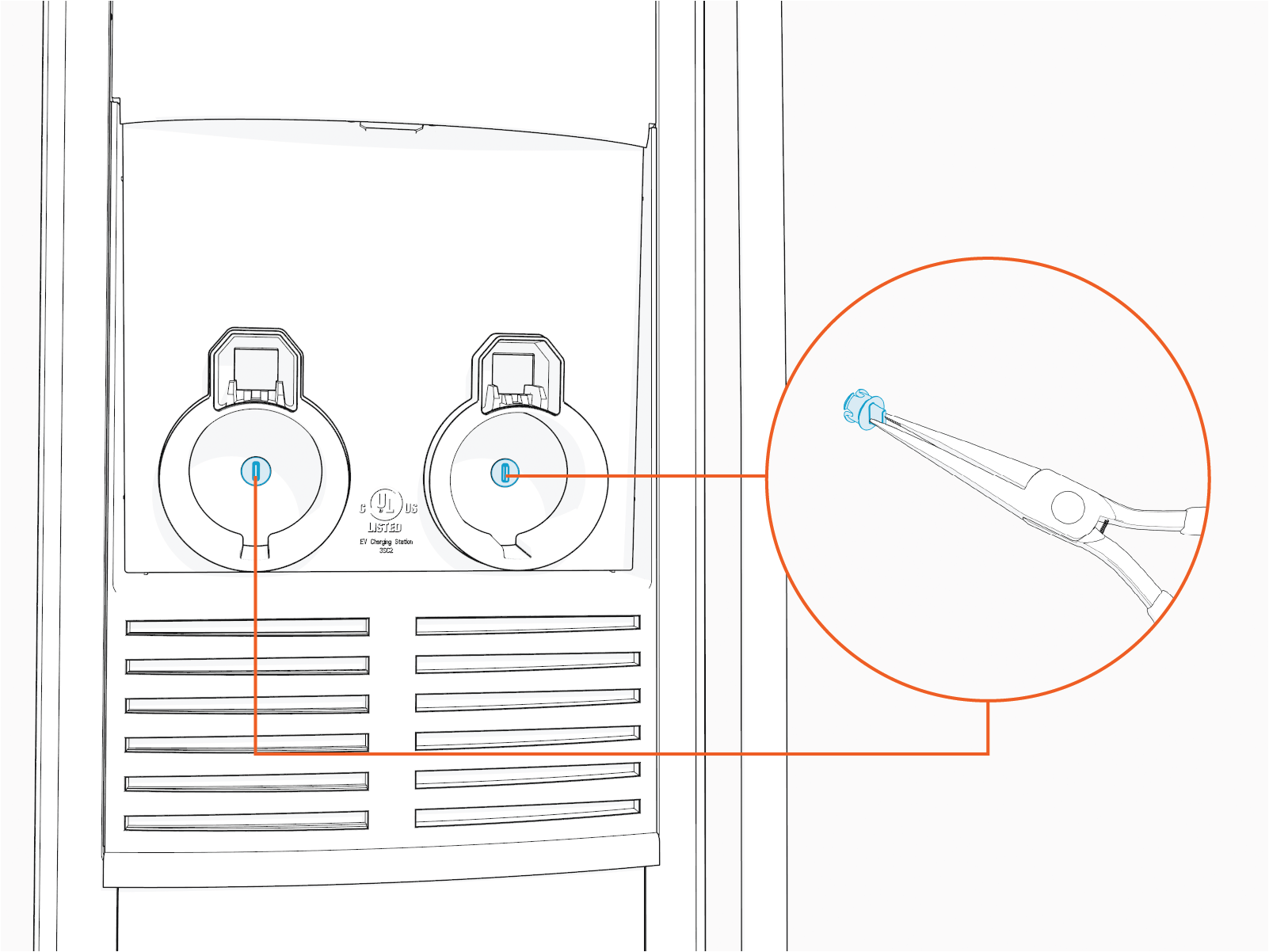
Use a thin/flat tool (small screwdriver, zip tie or coffee stirrer etc).
Do not use an object that is thick or wide. -
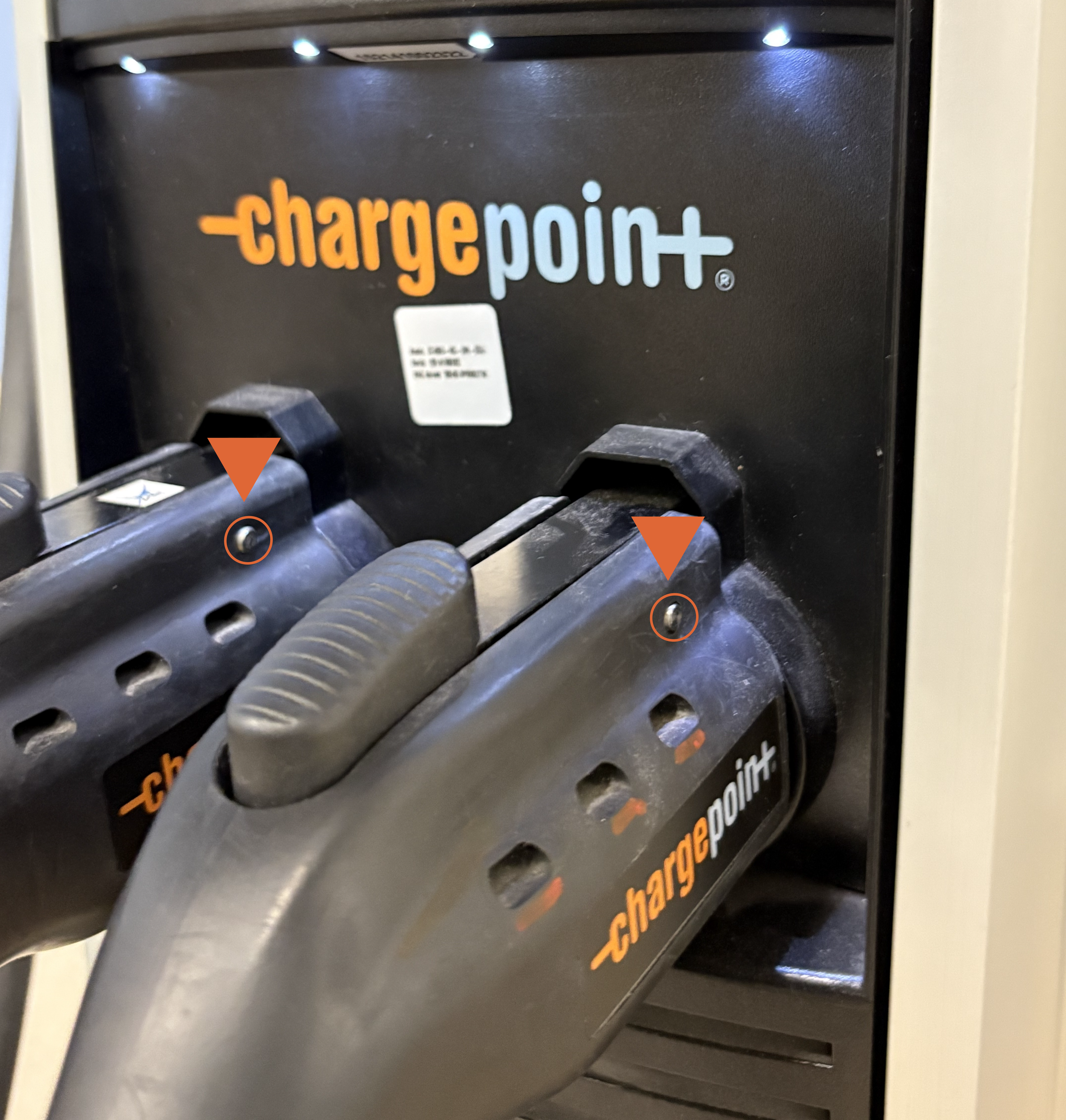
Locate the silver/grey latch pin in the connector handle.
-
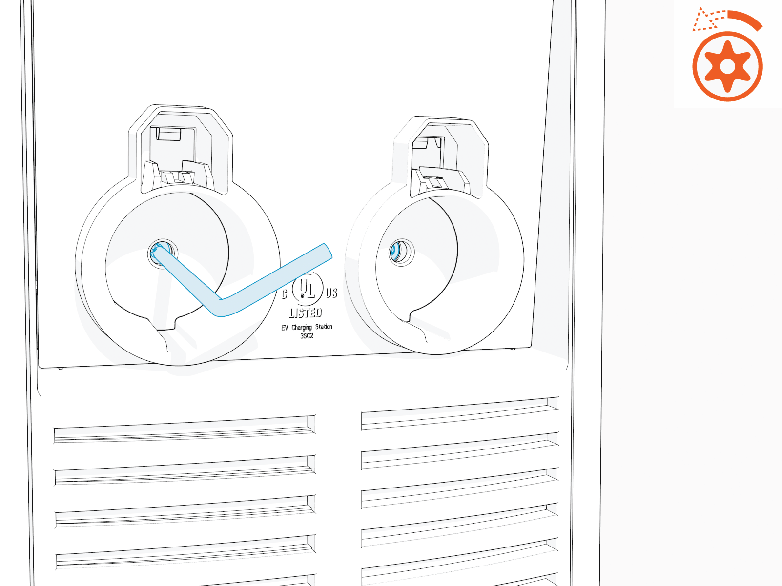
Insert the thin/flat tool into the pin slot and push the guide pin out.
Insert the thin/flat tool to the left or right, depending on the side of the latch pin located on the connector handle (left to right or vice versa).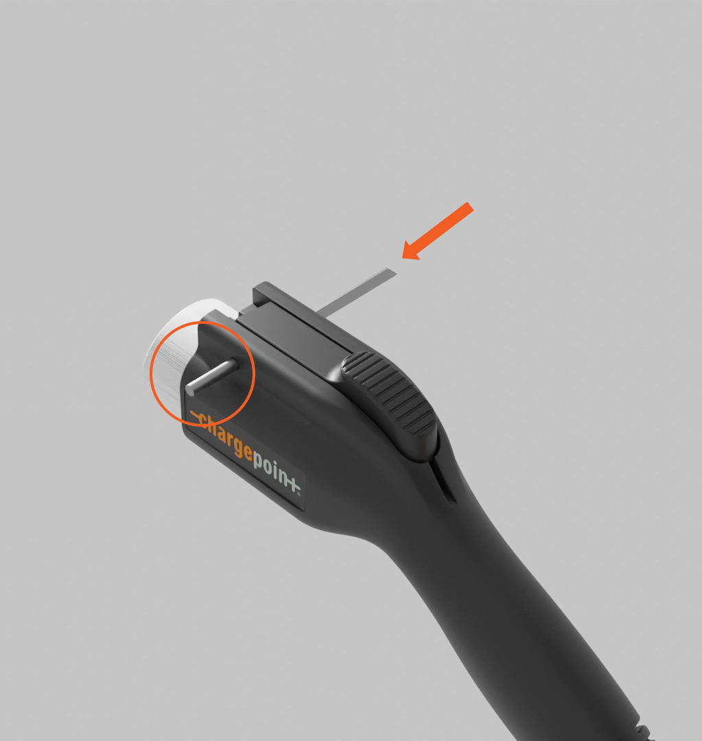
-
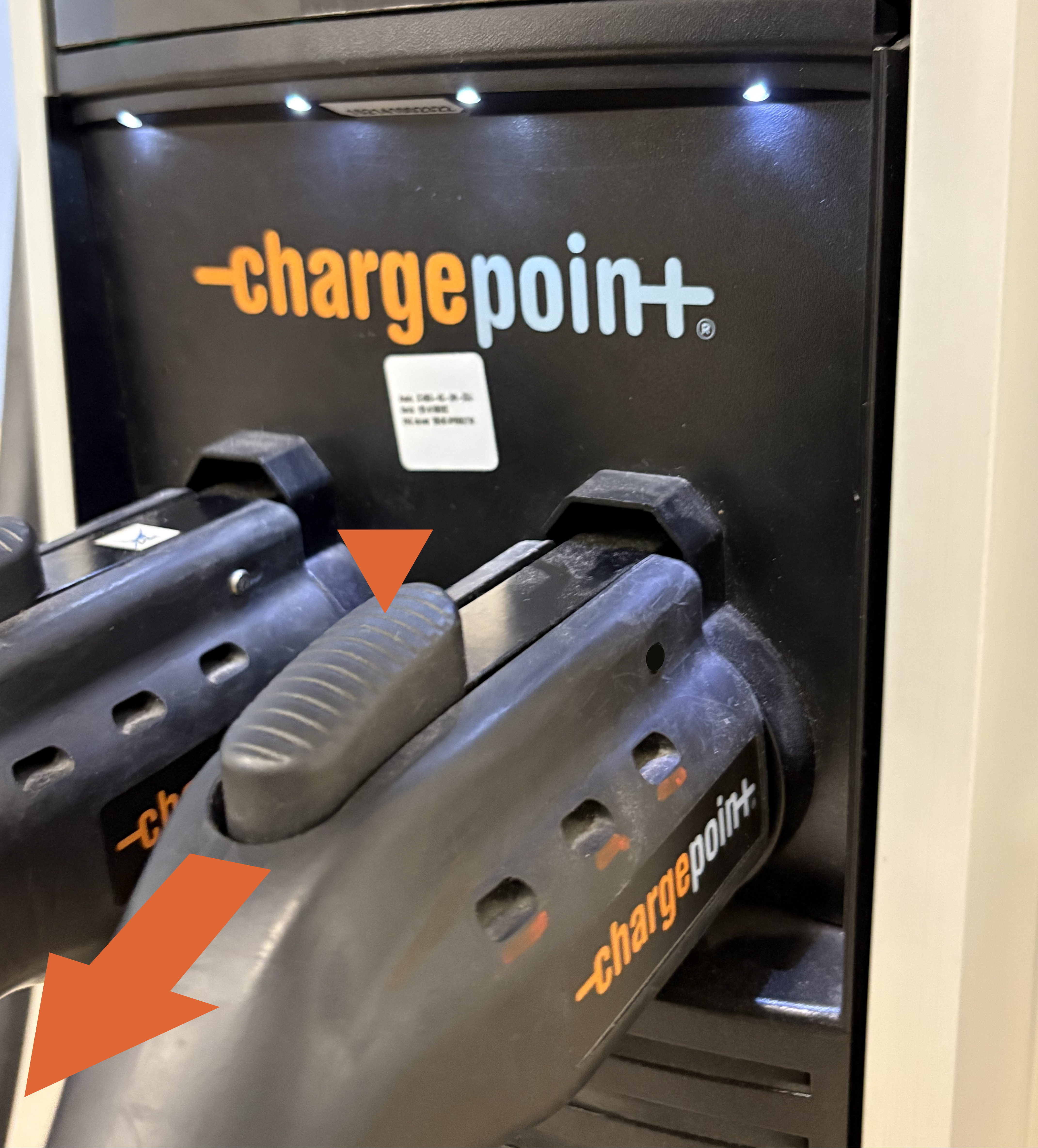
Press the latch button on top of the connector handle and pull the connector handle out of the holster.
-
-
Use needle nose pliers to remove the holster screw plugs.
-
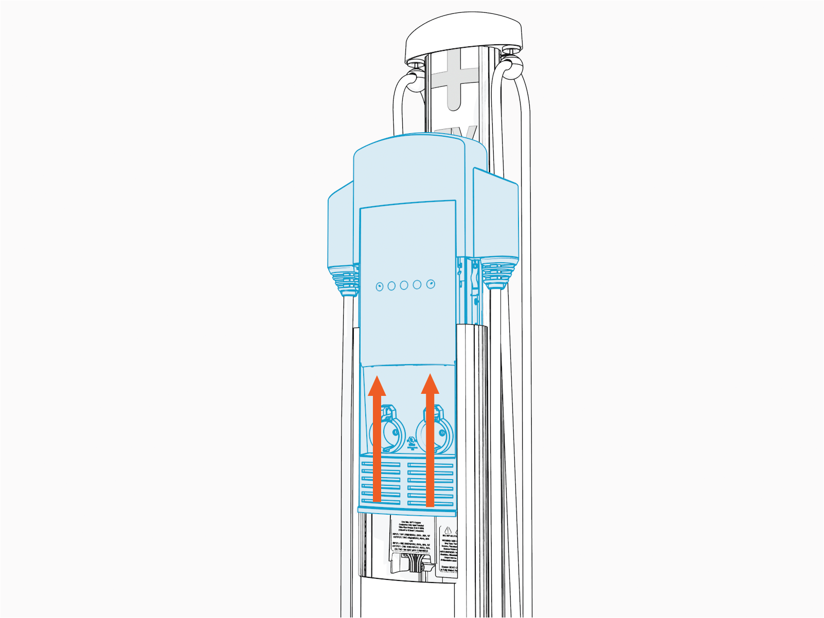
Use the T25 Security screwdriver to loosen, but not remove, the security Torx screws.
-
Raise the head assembly.
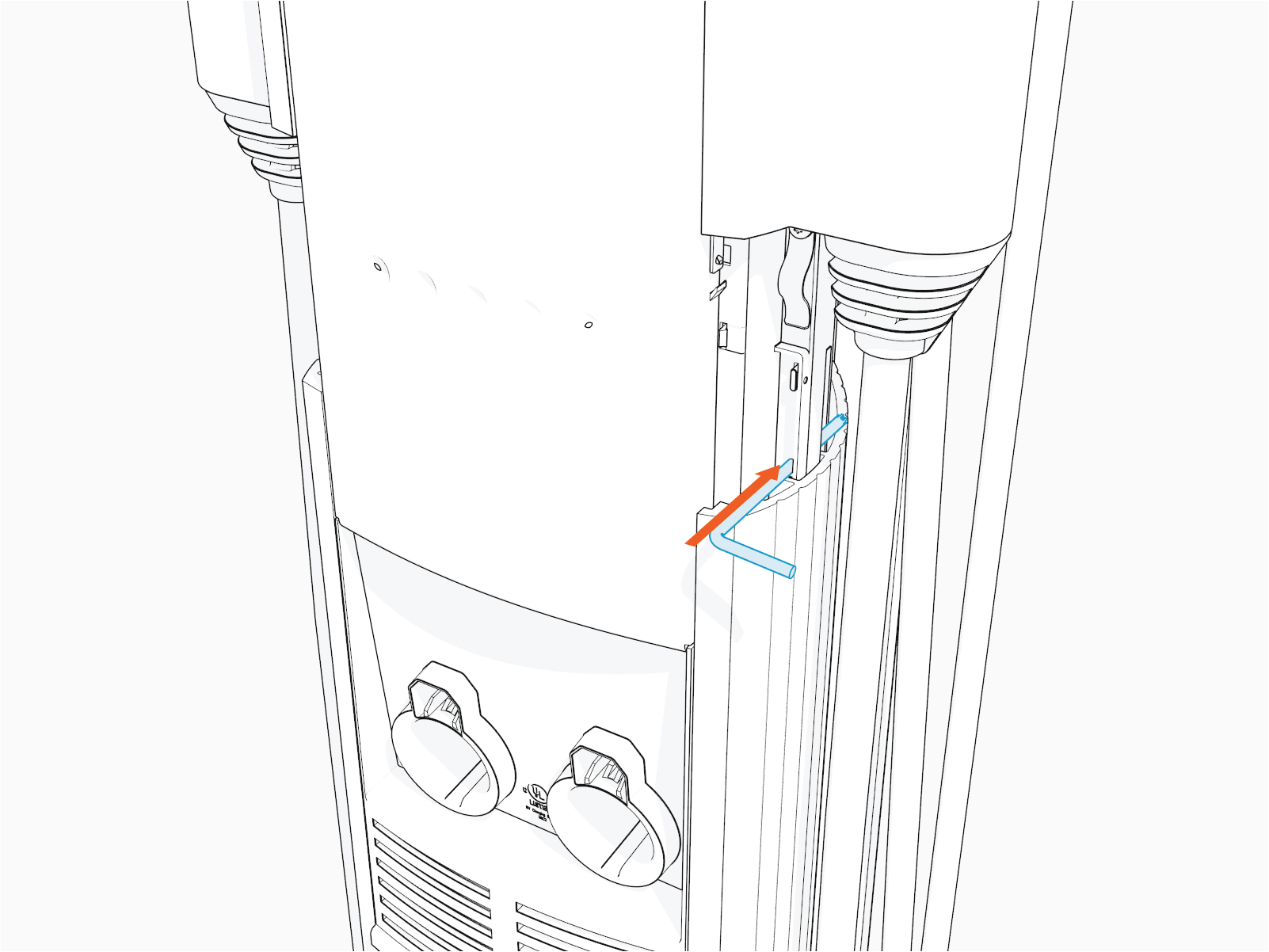
-
Insert the T25 Security screwdriver into the lower of two holes on the right side (as you face the station).
 If there is a label applied to the black plastic cover of the power plate, make note of what it says. It may note that:
-
Power sharing jumpers are installed
Or
- Power select options are in use to limit total station current for the circuit.
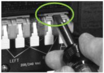
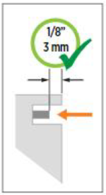 Ensure both jumpers are fully seated. The jumpers should recede 3 mm (1/8 in) below the outer surface of the terminal block, as shown. If they are flush, they are not fully inserted.
 -
Power sharing jumpers are installed
-
At the bottom of the now exposed power plate, locate the black plastic tab.

-
Push the black tab on the terminal block to release the terminal block cover, then slide the cover up until it locks into the raised position.
Verifying Voltages
Once proper wire placement has been verified, you need to check the voltages and impedances using a Digital multimeter (DMM) in parallel with a Solenoid voltage meter (wiggy).
Since digital meters (DMM) are high impedance devices, the amount of current that flows through the circuit while testing voltage with one is negligible.
- Adding the voltage measurements in parallel will confirm that the voltage measurements do not significantly deviate with current flow (unexpected impedance) and are not the result of a "floating" voltage on any wire.
- If voltages are not measured with some additional load -- like a parallel wiggy or dummy load -- the values will not confirm useful functionality or impedance, instead they will only verify proper placement of phases and ground. Loaded values must be measured for complete troubleshooting.
-
Test each wire relative to each other wire in the block, phase to phase, and phase to ground:
-
First, by connecting the DMM by itself and noting the voltage.
-
Next, by adding the wiggy in parallel and noting the voltage, while there is current flowing (using the alligator clips or pass through leads, if available).
-
-
Use the Test probe holes that are present behind the plastic latches of the wiring block.
Readings with and without the wiggy in parallel should be near 208 V or 240 V (Bonded Neutral Wye or Split Phase) phase to phase and 120 V phase to ground.- A significant deviation from these values can denote a wiring problem or unsupported supply type, refer to the CT4000 Installation Guide available at ChargePoint Product Reference Documentation.
-
A significant deviation from these values only with the wiggy in parallel would indicate an unexpected impedance in the system. This includes any of the following:
- A possibly worn or damaged beaker (or, pole within that breaker)
- Corrosion or insufficient bonding of the breaker to the bus bar or the breaker leads
- Insufficient bonding of neutral to ground at the panel.
Expected Voltage Readings
The following table lists the expected input voltage measurements (with or without the wiggy in parallel)
|
Connection Points (Measure Between) |
Volts (Nominal) |
|---|---|
|
L1R – L2R |
208/240 V |
|
L1L – L2L |
208/240 V |
|
L1R – GND |
120 V |
|
L2R – GND |
120 V |
|
L1L – GND |
120 V |
|
L2L – GND |
120 V |
|
The Line to Ground Maximum Voltage must never exceed 132 V.
|
|
Voltage Readings (with the DMM alone)
Record the voltage readings in the below table.
|
Connection Points (Measure Between) |
Results: Volts (Nominal) |
|
L1R – L2R |
|
|
L1L – L2L |
|
|
L1R – GND |
|
|
L2R – GND |
|
|
L1L – GND |
|
|
L2L – GND |
Voltage Readings (with the DMM in parallel with the Solenoid Voltage Meter)
Record the voltage readings in the below table.
|
Connection Points (Measure Between) |
Results: Volts (Nominal) |
|
L1R – L2R |
|
|
L1L – L2L |
|
|
L1R – GND |
|
|
L2R – GND |
|
|
L1L – GND |
|
|
L2L – GND |
Verifying Connections
- You can power down the station to perform the physical checks.
- Make sure that you are not removing live wires from the power plate, and also that you are not removing jumpers while the power is still on.
- So, it is ideal that you complete the steps below while the station is powered off, but only after taking the voltage readings.
-
Inspect the topmost slots of the leftmost and rightmost pairs of wiring blocks and note if power share jumpers are installed.
If these jumpers are installed and the station did not show power sharing as enabled on the screen, contact ChargePoint's Support to enable the power sharing option in the software. Visit chargepoint.com/support to find your region’s technical support number. -
Inspect the leads going into the wiring block - these should be 6 or 8 gauge copper, stripped half an inch, and fully seated.
-
Inspect the latches for the wiring block - all should be snapped fully down (vertical).
-
If a station is wired for single port or has power share jumpers installed:
-
The hot wires from a single 240 V or 40 A Double Pole breaker should be connected to the #2 and #5 position (right side of each outer pair)

-
The neutral wire (grounded/earth bonded at the panel) should be connected to the #3 (center) position.
 should be connected to the third (center) position.")
-
-
If a station is wired for dual port use and does not have power share jumpers installed:
-
The hot leads from one 240 V or 40 A Double Pole breaker should be connected to the #2 and #5 position (right side of each outer pair)

-
The hot leads from the other 240 V or 40 A Double Pole breaker should be connected to the #1 and #4 position (left side of each outer pair)

-
The neutral wire (grounded/earth bonded at the panel) should be connected to the #3 (center) position.
 To ensure that breakers and phases have not been crossed, it is best to verify each hot wire to ground with only one breaker on, and then again with only the other breaker on.
 -
Ensure that there is proper earth connection at the main transformer side also. The Neutral and Chassis Ground should be bonded in the main transformer as shown below:

-
Power On the Station
As you had powered off the station to perform the physical checks, you need to also do these steps:
-
Power the station back on.
-
Put the head unit back in place.
-
Lock it in.
-
Confirm that there are no faults on the display.
