Pole Mount Kit Installation Guide
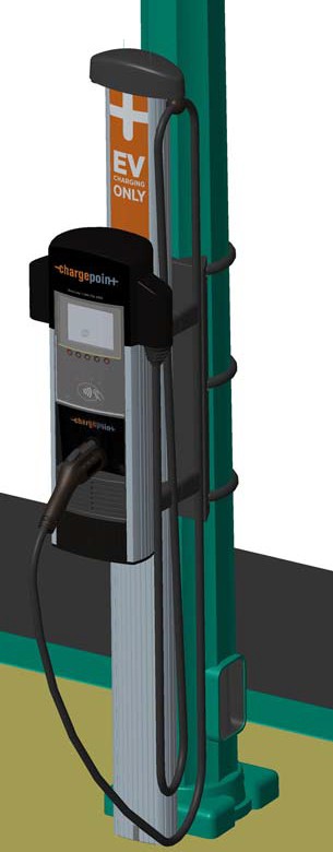
This section provides step-by-step instructions on how to install a CT4000 ChargePoint® charging station on a street lighting pole.
Before Installing the CT4000 Pole Mount
Installation must be performed by qualified personnel only.
-
Ensure that the installation site has been adequately evaluated for access to power and is suitable for vehicle parking. Refer to the CT4000 Family Installation Guide to ensure proper wiring is available at the installation pole.
-
Remove any signs on the pole that are below 72” from grade level.
-
Ensure that the CT4000 Wall Mount Housing is available at the installation site.
-
Ensure that the CT4000 Cable Management Kit (CMK
 Cable Management Kit) is available at the installation site.
 -
Ensure that the CT4000 Install guide is available at the installation site.
-
Review the contents of this document to familiarize yourself with the contents of each shipping box and the required installation steps.
Check Contents of Shipping Box
The ChargePoint Pole Mount Kit includes the following parts. Verify that you have received all of these parts in the shipping box.
|
Quantity |
Part Number |
Description |
|---|---|---|
|
PARTS |
||
|
1 |
21-001266-01 |
Bracket, CT4000, Lamp Pole Mount, Tall |
|
1 |
21-001267-01 |
Bracket Cover, CT4000, Lamp Pole Mount, Tall |
|
1 |
20-001436-01 |
Gasket, Rubber D-Seal, 1” Hollow, 6 ft |
|
HARDWARE |
||
|
1 |
10-001010-01 |
Strapping, SS302, ¾”x0.025”Thick |
|
3 |
10-001013-01 |
Strap Buckle,.75in,Std Duty,SS |
|
2 |
12-002458-01 |
Bushing, ½”Trade, Thick Panel, Snap-in |
|
1 |
12-002445-01 |
Bushing, ¾”Trade Knockout, Thick Wall |
|
4 |
11-001383-01 |
Screw, 3/8” 16 x 0.75”, Flange Head, Stainless Steel Serrated |
|
1 |
18-001034-01 |
Silicone Sealant, RTV, Dow Corning 700,3 oz (90 ml) |
It is assumed that the CT4000 Pole Mount is being installed at the same time as a CT4000 Wall Mount Housing and a CT4000 Cable Management Kit. Parts from these units are also needed to complete the installation.
You Will Need:
-
Electric Drill
-
Hole saw or step drill, ¾” Trade Knockout Size (1 1/8”)
-
Ratchet and 9/16” Deep Hex Socket
-
Tape Measure
-
Strapping Tool (for example isostainless.com #T001)
-
Deburring Tool
-
3/8"-16 HSS Tap
-
5/16" HSS Drill Bit
-
#3 Phillips Screwdriver
-
Adjustable Wrench
-
Wire strippers / Cutters
-
Wire Fish Tape
Overview of Steps
The installation process involves the following steps:
-
Mount the bracket
-
Strap the bracket
-
Mount Bracket Cover and CMK
Cable Management Kit Rear Brackets -
Install the CT4000 Wall Housing and CMK
Cable Management KitThese steps are detailed in the remainder of this section. When these steps are completed, continue with the installation as described in the CT4000 Installation Guide.
RISK OF SHOCK
Before performing any procedure, the technician must disconnect the power to the charging station at the service panel. Follow local code to de-energize the applicable circuit and lockout/tagout the upstream breaker before proceeding. Use a multimeter and check that the power is off. Keep power off for the circuit until all cover panels are correctly reinstalled and the work is complete.
FAILURE TO FOLLOW THESE INSTRUCTIONS CAN RESULT IN SERIOUS INJURY, LOSS OF LIFE, OR PROPERTY DAMAGE.
Mount the Bracket
-
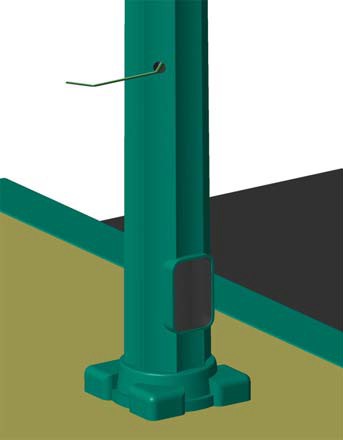
While facing the street, mark the center depression of the scallop one position to the right at 31-1/2” above grade.
-
Using the ¾” KO hole drill, drill a hole through the pole, being careful not to damage the existing wiring inside the pole.
-
Use the de-burring tool to remove all burrs and sharp edges from the hole.
-
Pull two power wires and the ground wire through the hole in the pole, leaving at last 18” of wire extending from the pole.
-
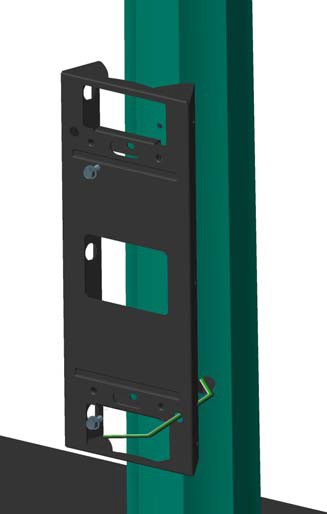
While holding the bracket so the top is 51-1/2” above grade, mark the upper and lower mounting holes. Using a 5/16” drill bit, drill the marked holes.
-
Tap the holes for 3/8”-1 6 thread.
-
Route the wiring through the hole in the bracket, as shown, then fasten the bracket to the pole using a 9/16” nut driver to tighten two of the 3/8”- 16 x 0.75” flange head screws. Tighten to 20 ft-lbs.
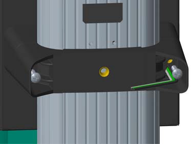
Strap the Bracket
-
Cut approximately 2-1/2 feet of the supplied stainless steel strap.
-
Cut 2 feet of the rubber D-shaped gasket.
-
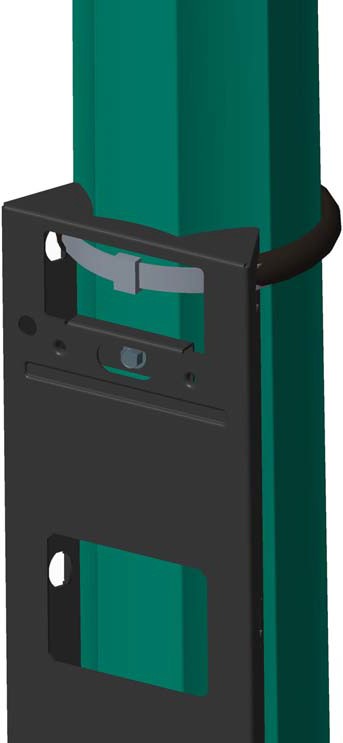
Slide the gasket over the strap so it is centered on the strap.
-
Run the strap through the top set of openings on the side of the bracket. Close the strapping seal through the bracket so that it will not be exposed later.
Detailed strapping instructions are available at http://isostainless.com/banding-tools.htm.
-
Repeat the above steps for the center and lower strapping positions.
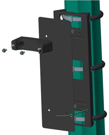
Mount Bracket Cover and CMK Rear Brackets
-
Insert two 3/8" - 16 hex screws into a CMK
Cable Management Kit rear bracket. -
Position the bracket cover over the pole mount bracket, aligning the four tapped holes.
Ensure that the wires are routed through the hole at the lower, right corner of the bracket cover.
-
Align and install the top rear CMK
Cable Management Kit bracket using a 9/16" deep socket at the top two holes. -
Install a 5/8" bushing through the bracket panel.
-
Route the wires through the hole in the lower rear CMK
Cable Management Kit bracket and align to the pole mount brackets, as shown. -
Tighten all four bolts to 20 ft-lbs.
Install the CT4000 Wall Housing and CMK
You are now ready to install the CT4000 CMK![]() Cable Management Kit and Wall Housing. For instructions, refer to the CT4000 Installation Guide (included in the shipping box with the CT4000 charging station’s top cap). When following the instructions, make these exceptions:
Cable Management Kit and Wall Housing. For instructions, refer to the CT4000 Installation Guide (included in the shipping box with the CT4000 charging station’s top cap). When following the instructions, make these exceptions:
-
When installing the CMK
Cable Management Kit’s front brackets, install the top bracket as described. However, for the lower bracket, you must first remove the screws. Then route the wires through the keyhole in the bracket and install the screws from the front. Tighten as described.
-
When installing the CT4000 Wall Housing, route the wires through the hole in the lower, right side of the housing. After tightening the bolts, apply the second ½” bushing to the hole.
Terminate the power wires and complete the installation.
