Connect Wiring
To connect the wiring to the station, follow these instructions:
- Use copper conductors only.
- Do not provide GFCI
 Ground-Fault Circuit Interrupter protection at the panel. The CT4000has built-in GFCI Ground-Fault Circuit Interrupter protection.
- In areas with frequent thunderstorms, add surge protection at the service panel for all circuits. Use new circuit breakers only.
- Ensure all power and ground connections (especially those at the breaker) are clean and tight. Remove all oxide from all conductors and terminals before connecting wiring.
- Although neutral is not used by CT4000 charging stations, neutral is used in the rest of the world. System neutral must be bonded to ground in the system so that all line to ground voltages are defined. Line to ground maximum voltages must never exceed 132 V.
Review Electrical Input and Output
Refer to the Datasheet for electrical input and output specifications.
Review Wiring Diagrams
The wiring diagrams that are below show wiring for installing a dual port CT4000 on a dual circuit. Two dedicated circuits are required. ChargePoint recommends installing each station with its own two-pole 40 A breaker, unless it is configured for operating at reduced power.
Grounding Requirements
The CT4000 must be connected to a grounded, metal, permanent wiring system. An equipment- grounding conductor must be run with circuit conductors and connected to an equipment-grounding terminal or lead on the CT4000.
A grounding conductor that complies with applicable codes must be grounded to earth at the service equipment or, when supplied by a separate system, at the supply transformer.
Ensure that a grounding conductor that complies with all applicable codes is properly grounded to earth at the service equipment or, when supplied by a separate system, at the supply transformer.
The voltage of either line, relative to ground, must not fall below 80 volts or a Floating Line Connection error occurs. Because the voltage of either line relative to ground must not be allowed to fluctuate, use only center-grounded systems. Neutral is not used to power the station but must be properly connected to ground, at the panel or transformer, to provide the necessary voltage reference relative to ground.
-
In a Wye system, connect the station to any two lines, as shown.
-
In a Delta system, connect the station to a center-tapped secondary only, where the center tap is bonded and the station is connected to the L1 and L3. This allows voltages to remain constant regardless of other loads that may be using the lines.
Connect to these Systems
To ensure proper operation and compatibility, connect the charging station only to the following electrical systems:
120/240 V AC
-
1Ø Bonded Neutral Station is connected to L1 and L2.
-
Neutral is not used.

120/208 V AC
-
3Ø Wye Bonded Neutral Station may be connected to any two lines.
-
Neutral is not used.

120/240 V AC, 3Ø Delta
-
Center tap grounded
-
Bonded neutral
-
Station must be connected to L1 and L2 only
-
Do not connect any part of the system to L3
-
Neutral is not used

Do Not Connect to these Systems
To prevent equipment damage or malfunction, do not connect the charging station to the following electrical systems:
120/208 V AC 3Ø Wye

-
Ungrounded Floating neutral
-
Voltage of either line to ground is undetermined
-
Neutral is not grounded
120/240 V AC 3Ø Delta, corner-grounded

Wiring for Dual or Single Port Stations
If the station is being configured for circuit sharing, go to Power Sharing.
-
Strip wires 13 mm (0.51 in).
 Cut wires straight across at 90° and not at an angle.
-
Push the black tab (a) on the terminal block to release the terminal block cover.

-
Slide the cover up until it locks into the raised position.
-
Lift all applicable levers on the terminal block.
-
Insert the ground wire into the center connector (GND
Ground). -
Push the center lever down until it clicks into its fully closed position.

-
Insert the 240 V AC L1 and L2 wires.
-
Push the levers down until they click into their fully closed position.
Wiring Diagram
240 V AC 1Ø Panel

-
Main Breaker
-
Neutral Bus
-
Ground Bus
-
Neutral
-
L2
-
L1
-
Left L1
-
Left L2
-
Right L1
-
Right L2
-
Ground
-
Left Port
-
Right Port
-
Strip wire 13 mm (0.51 in)
-
Local Service or Subpanel
-
120/240 V AC 1Ø
Bonded Neutral Required
Left and right refers to the left and right ports on the charging station.
For wiring for dual or single port stations, follow the steps below:
Single Port Wiring


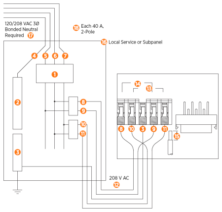
208 V AC 3Ø Panel
-
Main Breaker
-
Neutral Bus
-
Ground Bus
-
Neutral
-
L3
-
L2
-
L1
-
Left L1
-
Left L2
-
Right L1
-
Right L2
-
208 V AC
-
Right Port
-
Left Port
-
Strip wire 13 mm (0.51 in)
-
Local Service or Subpanel
-
120/208 V AC 3Ø
Bonded Neutral Required
-
Each 40 A, 2-Pole
Breaker may be connected to any two lines
Left and right refers to the left and right ports on the charging station.
Dual Port Wiring


Check Voltages
The following table lists the expected input voltage measurements.
|
Measure Between |
Volts (Nominal) |
|
L1R – L2R |
208/240 |
|
L1L – L2L |
208/240 |
|
L1R – GND |
120 |
|
L2R – GND |
120 |
|
L1L – GND |
120 |
|
L2L – GND |
120 |
|
The Line to Ground Maximum Voltage must never exceed 132 V.
|
|
To measure voltage, follow the steps below:
-
Turn power ON.
-
Using a solenoid type voltage tester, check that the voltages at the charging station’s terminal block are expected as listed in the table above.
-
Insert the meter probes into the holes under each lever and check the input voltage as listed in the table above.
-
If the voltages are not as expected, ensure that the wiring has been properly connected. Refer to the detailed Wiring Diagram in this chapter.
-
For grounding requirements, see the CT4000 Datasheet.

-
-
Resolve any wiring issues and ensure that voltages are as expected.
-
Turn power OFF.
If the power management kit is available, proceed to the next topic, Power Sharing. If the power management kit is not available, proceed to the topic, Install the Head Assembly and Top Cap to install the SIM card for U.S. or Canada as well as to install the head assembly and top cap.
