Field Upgrade Procedure: CAT 4 MultiTech Modem
This section describes the steps to add a LTE![]() Long Term Evolution Cat 4 MultiTech modem to a CT4000 charging station. The modem comes attached to the supplied mounting bracket. The mounting bracket mounts to the CT4000 without tools. The supplied antenna attaches with pressure sensitive adhesive. The modem gets power from, and communicates with, the CT4000 via the supplied USB
Long Term Evolution Cat 4 MultiTech modem to a CT4000 charging station. The modem comes attached to the supplied mounting bracket. The mounting bracket mounts to the CT4000 without tools. The supplied antenna attaches with pressure sensitive adhesive. The modem gets power from, and communicates with, the CT4000 via the supplied USB![]() Universal Serial Bus cable.
Universal Serial Bus cable.
Supplied Items:

-
Antennas (2)
-
USB
 Universal Serial Bus cable
 -
Modem/mounting plate assembly including SIM card (installed in modem)
You Will Need:

-
ChargePoint card or a smartphone
with ChargePoint mobile app installed -
ChargePoint installer login credentials
-
T25 tamper-resistant Torx driver
-
8 mm (5/16 in) combination wrench
-
Phillips screwdriver (not shown)
-
Needle nose pliers (not shown)
-
Clean towel or paper towels (not shown)
Overview of Steps
-
Confirm Software Version
-
Remove the Head Assembly from the Housing
-
Install the Antennas
-
Install the Modem
-
Replace the Head Assembly on the Housing
Confirm the Software Version on the CT4000
CT4000 v4.4.0.49 or later supports the LTE![]() Long Term Evolution CAT 4 MultiTech modem. On the CT4000 screen, select Help > About to determine the version. If the software version is lower than v4.4.0.49, contact ChargePoint Support: chargepoint.com/support.
Long Term Evolution CAT 4 MultiTech modem. On the CT4000 screen, select Help > About to determine the version. If the software version is lower than v4.4.0.49, contact ChargePoint Support: chargepoint.com/support.
Remove the Head Assembly from the Housing
-
Use your ChargePoint card or the mobile app to start a charging session, unlock the charging cables, and set them gently down.
-
Disconnect the power to the CT4000 at the service panel.
RISK OF SHOCK
Before performing any procedure, the technician must disconnect the power to the charging station at the service panel. Follow local code to de-energize the applicable circuit and lockout/tagout the upstream breaker before proceeding. Use a multimeter and check that the power is off. Keep power off for the circuit until all cover panels are correctly reinstalled and the work is complete.
FAILURE TO FOLLOW THESE INSTRUCTIONS CAN RESULT IN SERIOUS INJURY, LOSS OF LIFE, OR PROPERTY DAMAGE. -
Use needle nose pliers to remove the rubber plugs from inside the holsters (a). Save these for reuse.

-
Use a T25 tamper-resistant Torx driver to loosen, but not remove, the security screws inside the holsters (b).

-
Raise the head assembly high enough to access the terminal block. Insert a T25 tamper-resistant Torx driver into the hole (c) on the side of the side of the head assembly to hold the head assembly in the raised position.

-
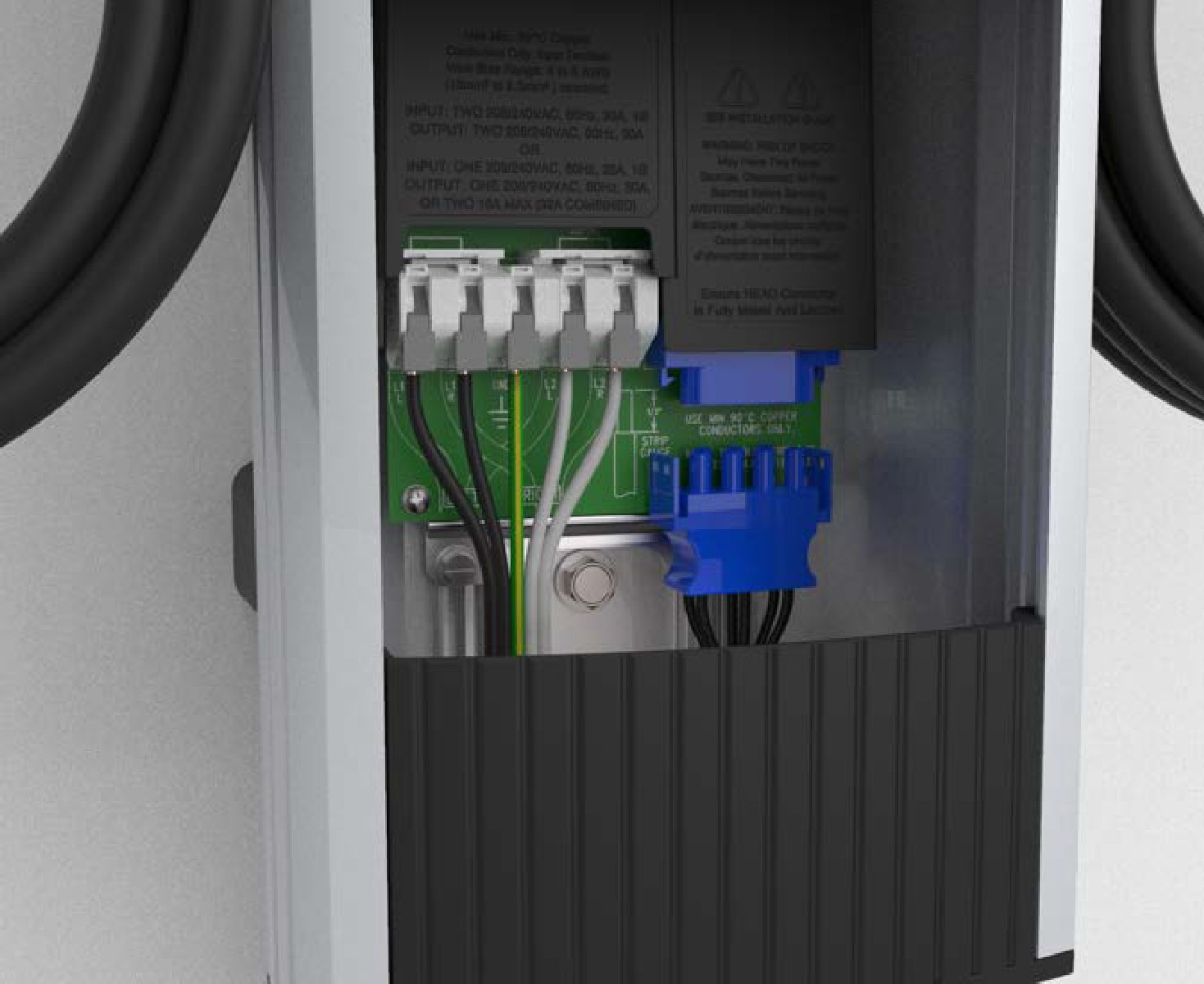
Push the black tab on the power plate (d) to release the power plate shroud, then slide the shroud up until it locks into the raised position.

-
Disconnect the blue connector by pressing the side tabs while rocking the connector side to side and pulling downward.
-
Remove the T25 Torx driver and lift the existing head assembly upward to remove. Place the head assembly on a blanket or other soft surface to prevent damage while completing this procedure.
Install the Antennas
-
Clean the mounting surface with a clean, damp cloth to remove all dust and dirt. Dry with a clean cloth or paper towel.
-
Remove the liner from the adhesive.

-
Apply the antennas (a) to the back of the head as shown. Press firmly to ensure proper adhesion.

Install the Modem
-
Confirm the modem has a SIM card installed and that it is fully inserted. It might be pre-installed and there might be a piece of tape over the SIM opening. Do not remove the tape.

If the modem does not have a SIM card, contact ChargePoint Support: chargepoint.com/support.
-
Press the bracket into the back of the CT4000 head until it is completely seated.
-
Connect the antenna cables as shown (b). Ensure the antenna cables and ferrite are tucked in beneath the modem bracket to prevent catching on the housing when the head is replaced.
-
Connect the grounding wire from the modem bracket to the frame of the CT4000 (c).
-
Install the USB
Universal Serial Bus cable. Connect the “A” end to the USB Universal Serial Bus jack in the bottom of the CT4000 and the “Mini B” end to the modem, to form a drip loop at the modem end as shown (d).
-
Be sure all cables are tucked in behind the bracket to prevent catching on the housing when the head is replaced.
Replace the Head Assembly on the Housing
-
Re-install the head assembly according to the steps above.
-
Connect the power connector.
-
Lower the power plate cover.
-
Wait for at least two minutes for the station to boot and the modem to report signal strength. It must indicate -75 dBm or greater. If the station does not boot, contact ChargePoint Support: chargepoint.com/support.
