Service Bulletin: Faulty Door Sensor Setup Leading to Charging Disruptions
Bulletin Published: November, 2025
Affected Model: Some ChargePoint Power Blocks
Failure: Improper installation of door sensors and magnets may prevent DC charging stations from detecting proper door closure. This can lead to charging interruptions, system faults, and delayed deployment.
Required Action: Before replacing the sensor, check the magnet orientation, the spacing between the magnet and the reed sensor, and inspect the reed sensor Molex connector. If the problem continues, follow the instructions to replace the door sensor.
- If the charging station is not installed, commissioned, or serviced by a ChargePoint certified technician using a ChargePoint-approved method, it is excluded from all ChargePoint and other warranties and ChargePoint is not responsible.
- You must be a licensed electrician and complete training at https://www.chargepoint.com/partners/training-certification to become ChargePoint certified and to access ChargePoint's web-based installer tools or ChargePoint Installer app.
For assistance, go to chargepoint.com/support and contact technical support using the appropriate region-specific number.
Introduction
Some DC charging stations may not detect door closure correctly. This can stop charging, cause system faults, and delay deployment.
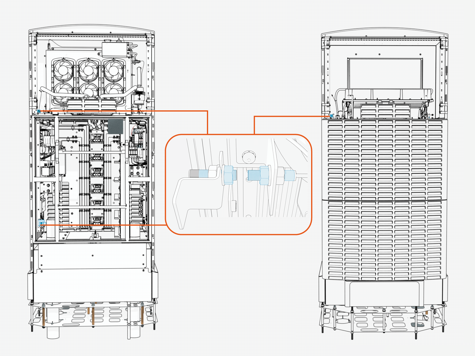
The following image shows the location of the door sensors in the Power Block.
Possible Causes
-
The magnet is oriented backwards, where potting side is facing the sensor.
-
The magnet is too far from the reed sensor
-
The reed sensor Molex connector is loose or damaged
Troubleshooting
Check these conditions before replacing the sensor. If the problem continues after these checks, replace the sensor as described in this bulletin.
-
Make sure the magnet and sensor are aligned in the correct orientation, refer to the following image.

-
Incorrect: The potting side of the magnet faces the threaded side of the sensor.
-
Incorrect: The magnet and sensor are misaligned, their threaded ends do not face each other.
-
Correct: The threaded side of the magnet and the threaded side of the sensor face each other and are properly aligned.
-
-
Inspect the Molex connector for bent pins, corrosion, or loose fit.

-
Measure the gap (a) between the threaded sides of the sensor and magnet, and ensure the gap is less than 10 mm and as close as possible.
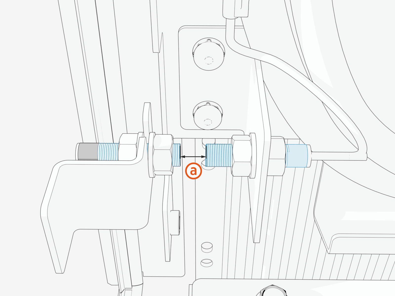 If needed, replace standard M8 nuts (x2) with the thin M8 nuts (x2) on both sides of the magnet to reduce the gap (a).
Replace the Door Sensor
To replace a door sensor, do the following steps:
Bring these Tools
| Icon | Description | Icon | Description |
|---|---|---|---|
|
|
13 mm hex socket |
|
13 mm hex wrench |
|
|
Stepladder |
|
Multimeter |
|
|
Lockout or tagout equipment |
|
Padlock key or code (only if your site requires it) |
|
|
Phillips screwdriver |
|
|
Power Off
-
Before any procedure, disconnect the power.
-
Depending on the Express Plus architecture used at the site, the Power Block may be electrically connected to other Power Block HV DC
 High Voltage Direct Current power sources through a Power Link or Power Hub. Consult the site drawings to ensure power is disconnected from all connected Power Blocks.
-
Depending on the Express Plus architecture used at the site, the Power Block may be electrically connected to other Power Block HV DC
- Follow local code and site lockout/tagout procedure to de-energize the station.
- Wait for energy to dissipate (approximately five minutes).
- Keep power off until all covers and panels are reinstalled and the work is complete.
-
End all charging sessions and activity.
Failure to end the charging session before beginning service could damage hardware components. Such damaged components may need to be replaced, and this may be costly. -
Power off all upstream components as follows:
Powering off all upstream components will shut down all components at the site. Powering off the 48 V input is not required.-
Disconnect power at the site electrical panel.
-
Wait the required time for energy to dissipate (see label on the product).
-
-
Use a multimeter to confirm that power is off.
-
Perform service or maintenance.
Disconnect Power
Disconnect power at the site electrical panel and use a lockout equipment to test that power is off.

Check Power Block Status Light
To check the Power Block status light, complete the following steps:
-
Open the security panel.

-
The status light (a) must be off (unlit). If the status light is on (glowing any color), do not proceed further with servicing. Wait the required time for energy to dissipate (see safety label (b) on the product).
Remove Upper Panel (Front or Rear)
-
Open the security panel and unlock and remove the padlock.

-
Slowly press and push the upper panel sides up to disengage the hooks (x4) behind the panel.

REVERSE THE ABOVE STEPS TO REINSTALL THE PANEL.
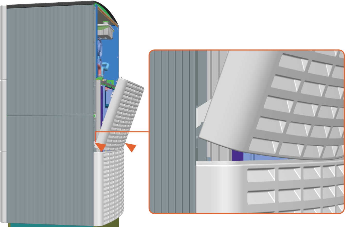
Remove Mid or Lower Panel (Front or Rear)
-
Pull the hook levers (x2) out to disengage the hooks (x2) behind the panel's upper side.

-
While the hook levers (x2) are pulled out, tilt out the panel's upper side to remove.

-
Repeat for the lower panel.
Reinstall Mid or Lower Panel (Front or Rear)
-
Align and seat the lower hooks (x2).
-
Tilt in the upper side to engage the upper hooks (x2).

-
Repeat for the lower panel.
Remove Front Door
-
Hold the door to support it and disengage the latches (x2).

-
Hold the door handles (x2) and tilt out to lift the door off of the flange at the bottom of the door.

REVERSE THE ABOVE STEPS TO REINSTALL THE DOOR.
Remove the Transparent Shield
-
Loosen six captive screws by hand for each transparent shield (or, use a #5 Phillips screwdriver).
.")
-
Slightly rotate out the edge with the screws.

Reinstall the Transparent Shield
This step is required only after completing the replacement of door sensors.
-
Align the tabs on the transparent panel with the slots in the racks. Insert the tabs into the slots.
For the left shield only, align the hole over the door switch.
-
Tighten the captive screws.

Remove the Door Sensor and Magnet
The following procedure includes images that show a typical door sensor and magnet configuration. Mounting brackets may vary by location.
-
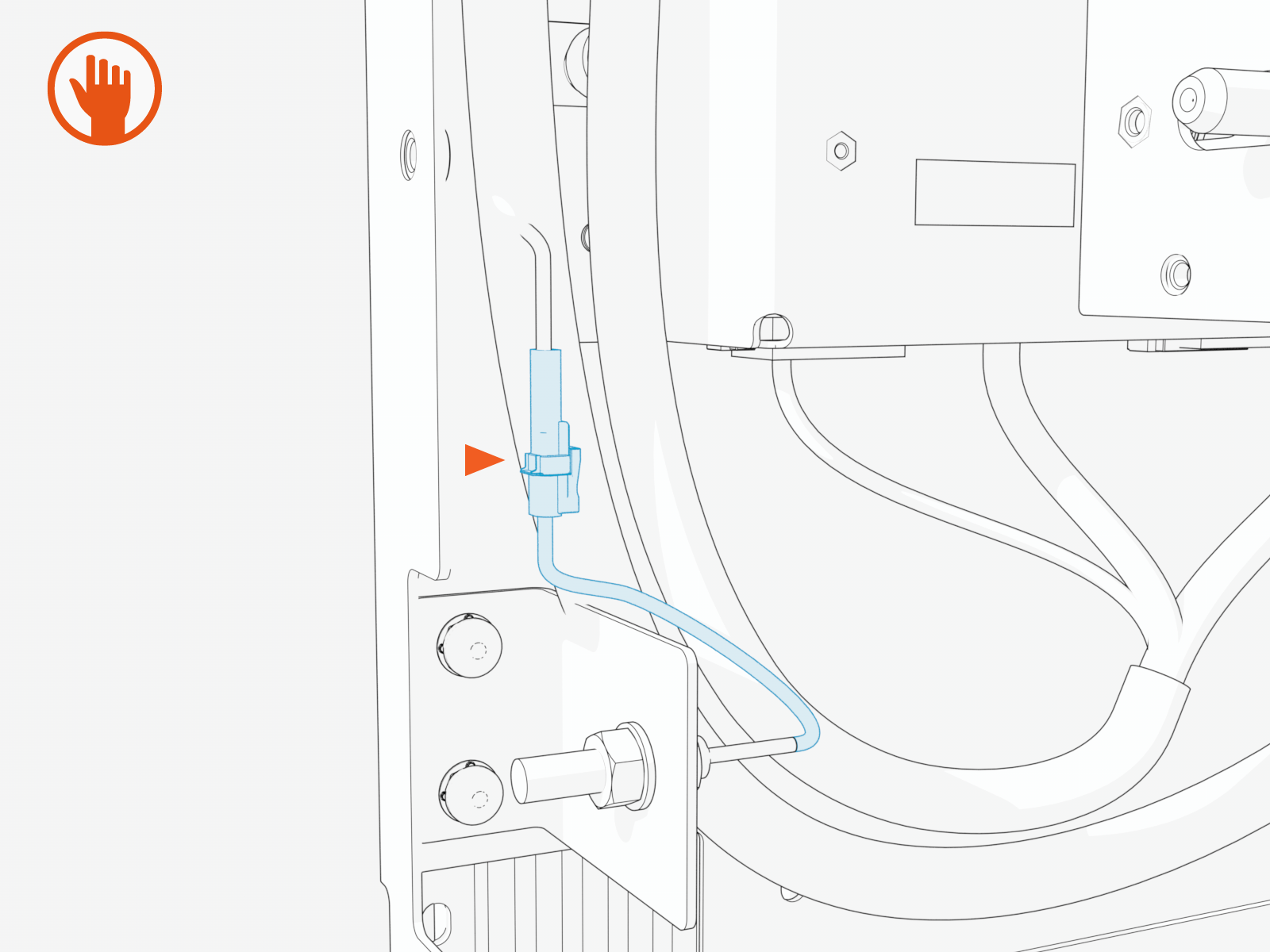
Disconnect the reed sensor cable.
-
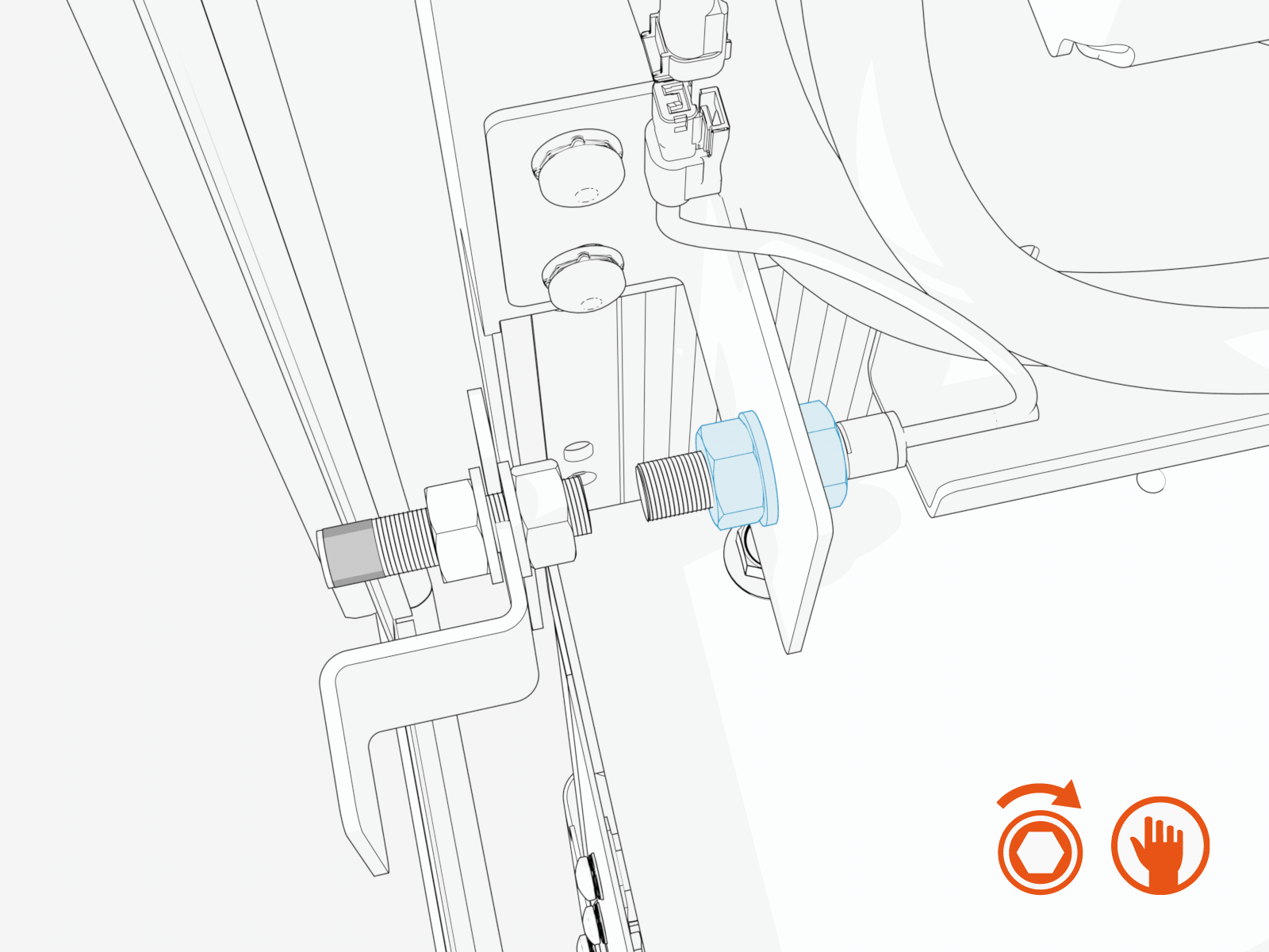
Loosen and remove the M8 nuts (x2) and washers (x2) securing the magnet.
Removing the M8 nut and washer on the threaded side of the magnet allows the magnet to slide out, while the nut and washer on the potting side remain attached.
-
Carefully remove the magnet from the bracket.
-
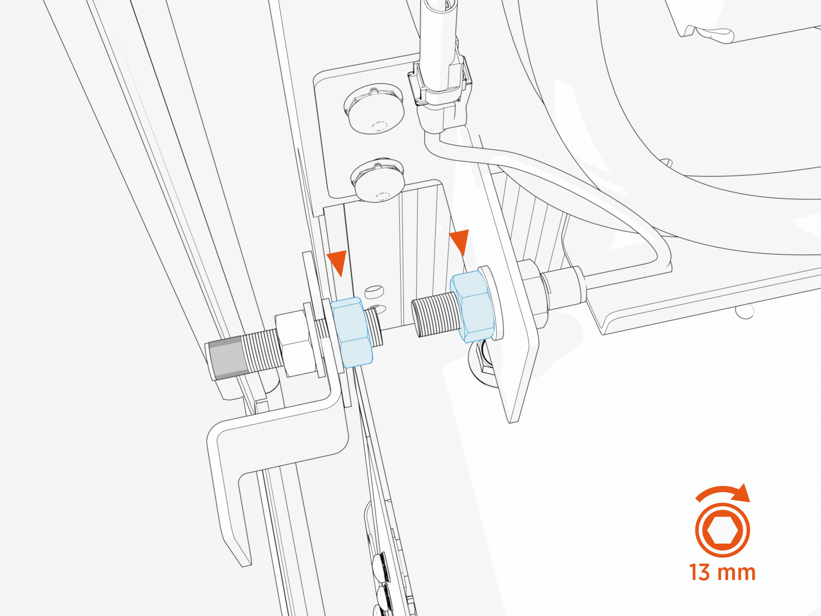
Loosen and remove the M8 nuts (x2) and washers (x2) securing the sensor.
Removing the M8 nut and washer on the threaded side of the sensor allows the sensor to slide out, while the nut and washer on the connector side remain attached.
-
Carefully remove the sensor from the bracket.
Reinstall the Door Sensor and Magnet
-
Place the washers (x2) and the magnet in its position.
-
Secure with M8 nuts (x2) and hand-tighten.

-
Place the washers (x2) and the sensor in its position.
-
Secure with M8 nuts (x2) and hand-tighten.
-
Check that all conditions listed in the Troubleshooting section are met before proceeding to torque the nuts.
-
Use the 13 mm socket, torque the nuts to 14 Nm (124 in-lb).
Power On
To power on, ensure that the guidelines below are applied:
-
Ensure all doors and panels, covers, vinyl signs, and all other parts have been correctly installed and the work is complete.
-
Turn on power at the same points that you turned it off.
If the site has a remote shunt trip switch, ensure that the switch is in the operating position. -
Wait for self-diagnostics to run. The system may take several minutes to initiate. You may see messages intermittently until the system fully boots up.
Station Self-Diagnostic Tasks Self-Diagnostic
After Installation
After Service or Power Outage
Electrical safety checks
✔
✔
Lighting checks
✔
✔
Display panel checks
✔
✔
Component operation checks
✔
✔
Network connectivity checks
✔
✔
Installation Wizard
(for the installer to complete configuration and
pinpoint the station on maps)✔
—
-
View diagnostics information.
-
Log in to the ChargePoint Platform at na.chargepoint.com or ca.chargepoint.com or eu.chargepoint.com.
-
Select Stations.
-
Apply filters to locate the desired station.
-
Select the station name to view the station-specific information.
If a red status alert appears, contact ChargePoint immediately at chargepoint.com/support. A yellow status alert provides you with information that may require action (such as maintenance action) or no action. -
-
If you have not yet configured the station (such as pricing, messaging, and additional options), do so after installation or service is complete. Refer to the Express Plus Operation and Maintenance Guide.
Report Completion to ChargePoint
Contact ChargePoint Support at chargepoint.com/support to report completion of the repair procedures, and any negative findings during the station inspection.
