Civil and Mechanical Design
Use the guidance below to design the civil and mechanical aspects of the site.
Component Dimensions and Weight
The Express 280 is a vertical enclosure with the dimensions shown here.
|
Generic Specifications |
|
|---|---|
|
Station Enclosure Dimensions |
2413 mm H x 712 mm W x 420 mm D (95 in x 28 in x 16.5 in)* |
|
Power Module Dimensions |
760 mm H x 430 mm W x 130 mm D (30 in x 16.9 in x 5.1 in) |
|
Station Weight (without Power Modules) |
250 kg (551 lb) |
|
Power Module Weight |
45 kg (98.5 lb) |
* Includes Cable Management Kit (CMK![]() Cable Management Kit)
Cable Management Kit)
Mounting Specifications for Pads
The station can be installed on either a newly poured pad or an existing concrete surface. The mounting surface must be smooth and cannot exceed a slope of 6.35 mm per 304.8 mm (0.25 inches per foot).
The specifications are as follows:
-
At least 305 mm (12 in) deep (or deep enough to be 305 mm (12 in) below the frost line)
-
At least 1296 mm (51 in) on each side
-
Contains #4 rebar or larger, top and bottom, 305 mm (12 in) on center
-
Concrete 2500 PSI minimum
The above pad specifications are designed to meet these conditions:
-
170 mph wind speed
-
Wind Risk Category I
-
Wind Exposure D
-
Seismic Importance Factor 1.0
-
Hayward Fault with mapped spectral response accelerations Ss=2.45 S1=1.019
-
Seismic Design Category E
-
Foundation of Sandy Soil with allowable stress = 1500 psf, Cd = 1.33
In some extreme conditions, a larger pad would be required. For sites with less stringent seismic, soil, or wind conditions, a smaller pad might be possible.
If the existing pad does not meet the specifications above, it must be inspected and approved by a structural engineer for the station's dimensions and weight. If needed, give these structural design specifications to the structural engineer for verification:
| Component | Value |
|---|---|
|
Product Weight |
340 kg (750 lbs) |
|
Product Height from Ground |
2.413 m (7.917 ft) |
|
Product Width |
0.42 m (1.378 ft) |
|
Product Frontal Area |
Height * Width |
|
CG Height |
1.12 m (3.66 ft) |
|
Number of Anchor Bolts |
4 |
|
Bolt Pattern |
See dimensions below. |
|
Anchor Bolt Size |
M16 (5/8 in) |
|
Anchor Bolt Embedment |
229 mm (9 in) |
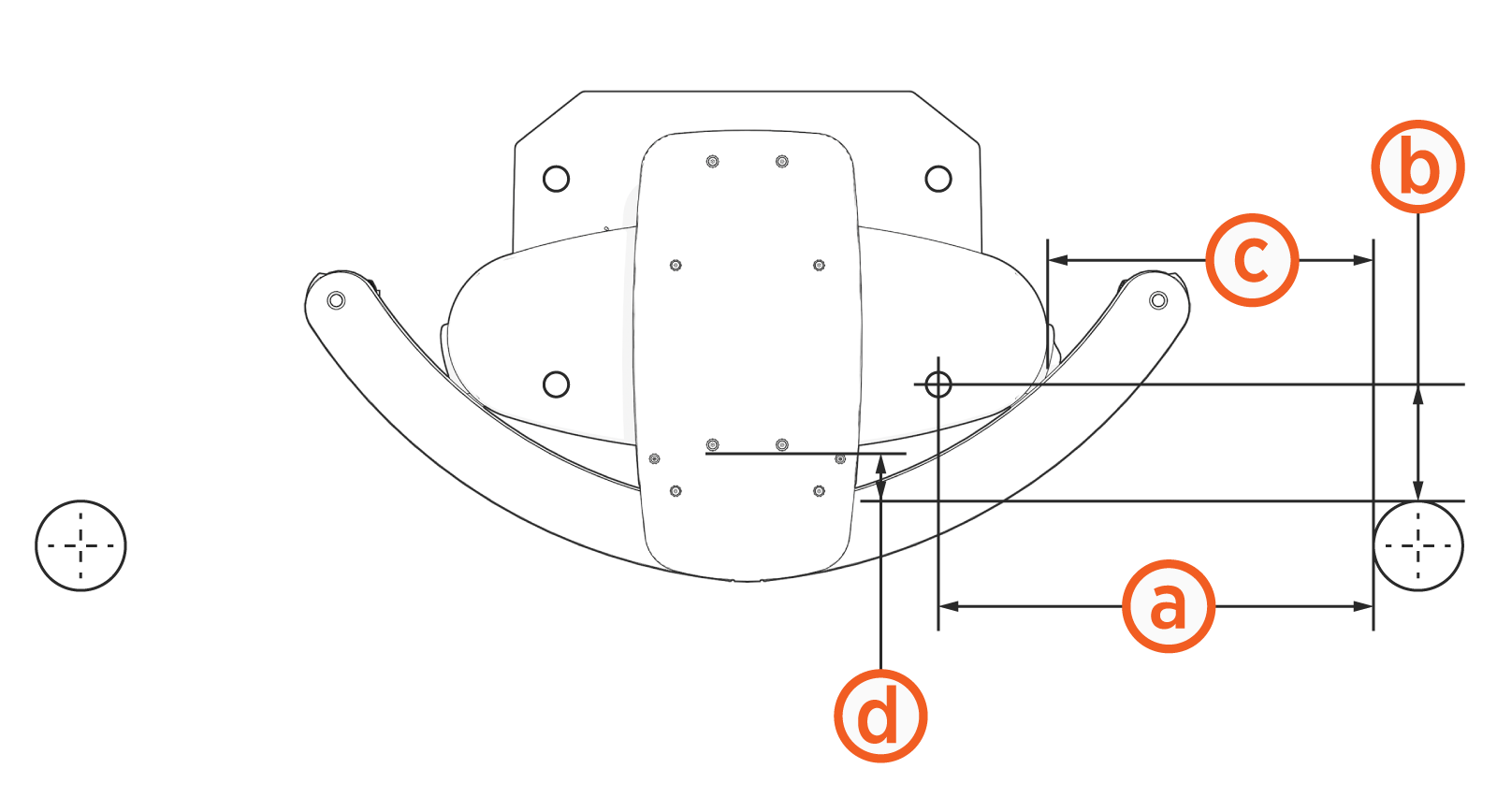
Express 280 stations use the DC Universal Concrete Mounting Template (CMT), which also fits other DC fast charging stations such as the Express 250. This CMT is embedded in a newly poured concrete pad to position both the anchor bolts and the conduit stub-ups detailed above.
For conduit and anchor bolt configurations and assembly instructions, see the Concrete Mounting Template Guide.
The anchor bolt pattern appears below.

Drainage
Ensure any site slopes, walls, or fencing do not trap water around the installation site.
Exposing the ChargePoint charging components to over 406 mm (16 in) of standing water could create an electrocution, shock, or fire hazard. Cut power to the charging station if it has been exposed to standing water and contact ChargePoint before the charging station is powered on.
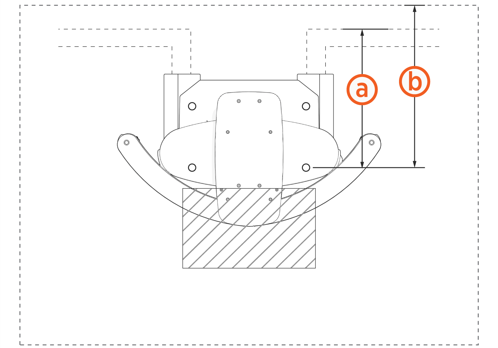
Clearances
The Express 280 requires the following minimum functional and service clearances:

(a) Service clearance of open space (not necessarily at system grade)
(b) Power Module service clearance (at grade, measured from station front): 330.2 mm (1 ft 1 in)
(c) Front service clearance (measured from station front): 609.6 mm (2 ft)
(d) Power Module service clearance (measured from front anchor bolt): 383 mm (1 ft 3.1 in)
(e) Power Module service clearance (measured from station center): 290 mm (11.4 in)
(f) Side service clearance (measured from station center): 1072 mm (3 ft 6 in)
(g) Front service clearance (measured from front anchor bolt): 510 mm (1 ft 8.1 in)
(h) Rear service clearance (measured from front anchor bolt): 663 mm (2 ft 2.1 in)
Allow 26 mm (1 in) clearance above the station if installing a Cable Management Kit (CMK![]() Cable Management Kit).
Cable Management Kit).
Rear clearance must be at grade level +/- 25 mm (1 in).
Refer to Ventilation and check local and regional code for any additional clearance requirements.
Surface Conduit Entry
You can install Express 280 DC fast charging stations at sites where you cannot pour a new concrete pad or run conductors underground. The Surface Conduit Entry (SCE![]() Surface Conduit Entry) kit allows surface drilling and epoxy installation of anchor bolts, as well as a rear conduit entry box for conductors to enter the station through surface wireways. The SCE
Surface Conduit Entry) kit allows surface drilling and epoxy installation of anchor bolts, as well as a rear conduit entry box for conductors to enter the station through surface wireways. The SCE![]() Surface Conduit Entry kit supports both Standalone and Paired installations. The SCE
Surface Conduit Entry kit supports both Standalone and Paired installations. The SCE![]() Surface Conduit Entry kit also supports adding above-ground conduit to pair an already-installed Standalone station with another Express 280 for shared DC output.
Surface Conduit Entry kit also supports adding above-ground conduit to pair an already-installed Standalone station with another Express 280 for shared DC output.
Before beginning work, check that the site meets the basic requirements outlined below, as illustrated in the following image. Measurements are listed in mm (in).
-
The panel breaker serving the charging station matches the site drawing requirements depending on local code and the type of installation: 80 kW Standalone, 160 kW Paired, 62.5 kW or 50 kW de-rated (when replacing a previous, lower-amperage system).
-
The smooth, level concrete has been approved by a structural engineer for the Express 280 dimensions and weight, OR conforms to these general specifications*:
-
At least 305 mm (1 ft) deep (or deep enough to be 305 mm (1 ft) below the frost line)
-
At least 1296 mm (4 ft 3 in) on each side
-
Contains #4 rebar top and bottom 305 mm (1 ft) on center
-
Concrete 2500 PSI minimum
-
-
The cellular signal strength at the station location has been tested and is consistently strong. If RSRQ is measured at -10 dB or better, then RSRP can be -90 dBm or better. If RSRQ cannot be measured or is not adequate, RSRP must be -85 dBm or better. Visit Connectivity for more information.
-
The service clearance of open space (not necessarily at system grade) extends a minimum of 610 mm (2 ft) beyond the station in front, and 1072 mm (3 ft 6 in) side to side centered on the station. See the images below for rear clearance depending on configuration.
* These pad specifications are applicable in most conditions. In some extreme conditions, a larger pad would be required.
If the conduit runs from the back of the SCE![]() Surface Conduit Entry to the side(s), with rigid wireway elbows:
Surface Conduit Entry to the side(s), with rigid wireway elbows:
-
The rear conduit clearance from the front anchor bolt at grade is 620 mm (24.4 in) (a)
-
The recommended extra rear service clearance of open space (not necessarily at grade) is 925 mm (36.4 in) (b)
If the conduit runs from the back of the SCE![]() Surface Conduit Entry straight back:
Surface Conduit Entry straight back:
-
The rear conduit clearance at grade is 470 mm (18.5 in) (a)
-
The recommended extra rear service clearance of open space (not necessarily at grade) is 775 mm (30.5 in) (b) from the front anchor

If the site does not meet these basic requirements, contact ChargePoint before continuing.
For more information, access ChargePoint documents at ChargePoint Product Reference Documentation.
Wheel Stops and Bollards
Bollards and wheel stops are not explicitly required by ChargePoint. However, ChargePoint recommends these best practices and considerations when designing the site:
-
Permanent bollards or wheel stops must not encroach upon the clearances listed in the clearance diagrams in this section. Removable bollards are allowed if service personnel have the ability to move them as needed.
-
Where permitted by code, wheel stops are preferred over bollards for head-in or back-in spaces.
Wheel Stops
Consider the following points when using the wheel stops:
-
Consider the average vehicle overhang distance for the largest type of vehicle (passenger, bus, etc.) as well as leaving space for the driver to walk up and access the station.
-
Position wheel stops to actively block at least one wheel, without presenting a trip hazard to pedestrians walking between vehicles.

(a) Wheel stop, positioned to actively block at least one wheel
(b) Cable reach radius: 3.76 m (12 ft 4 in)
(c) Recommended distance between wheel stop and station: 1371 mm (4 ft 6 in) for passenger vehicles
(d) Recommended distance for walk-up access: 609 mm (2 ft)
Bollards
Consider the following points when using a Bollard:
-
When bollards are required by code, needed for snowy areas, or needed for curbside spaces, ensure bollard placement does not interfere with removing and replacing charge cables in the station’s holsters.
-
Try to minimize bollard interference with the movement of charge cables between the station and the vehicle. Bollard height is recommended to be no higher than 914 mm (36 in) where needed.
-
Follow the measurements listed for bollards placement Express 280 standard (2.4 m) CMK
 Cable Management Kit:
(a) Anchor bolt to bollard inside edge: 391.95 mm (15.4 in)
(b) Anchor bolt to bollard front edge: 104 mm (4.1 in)
(c) Express 280 side to bollard inside edge: 257.00 mm (10.1 in)
(d) Express 280 front to bollard front edge: 55.54 mm (2.2 in)
-
Follow the measurements listed for bollards placement Express 280 tall (3.1 m) CMK
Cable Management Kit:
(a) Anchor bolt to bollard inside edge: 590.50 mm (23.25 in)
(b) Anchor bolt to bollard front edge: 104.00 mm (4.1 in)
(c) Express 280 side to bollard inside edge: 457.00 mm (18.0 in)
(d) Express 280 front to bollard front edge: 55.54 mm (2.2 in)
Pairing Previously Installed Charging Stations
If all site construction for paired charging is completed in advance, Express 280 stations can be initially installed as Standalone and paired at a later date. In that case, follow these additional steps:
-
During initial site construction, install DC and communication conduit or ducting (as applicable by region) in advance.
-
Extend side clearance at both DC conduit stub-up locations to 1.2 m (4 ft) to allow space for cable pulling equipment.
-
Run a pull rope through the larger DC conduit before landing the charging stations. Do not pull DC cable in advance, as it is too thick to hide inside the cover panels without risking damage or unwanted electrical contact.
-
Install a fishing tape in the smaller communication conduit to assist with routing the Ethernet cable later. If Ethernet is pulled in advance, leave 3.175 m (125 in) of wire above grade at each end.
-
Use duct seal compound to seal the ends of the DC and communications conduit stub-ups. Seal the ends of the fishing tape to hang outside the conduit.
-
Install the cover panels and extrusions on the Express 280 stations over the stub-ups as normal.
By only connecting AC wiring (and shunt trip if applicable), each station can perform as a Standalone station until the station owner is ready to pair them. At a later time, the stations can be paired by installing DC conductors, connecting Ethernet communication, and performing a firmware update if required. Refer to the Express 280 Installation Guide for further details.
Once two Express 280 are correctly paired, operation of both stations is inhibited if Ethernet connectivity is lost or one station loses power. This is a safety feature to prevent one Paired station from accidentally powering the other during maintenance.
Do not connect DC power between the charging stations until both stations are ready to complete the full pairing configuration. Station firmware updates are required to enable full Paired behavior. Connecting power before the charging station is properly configured can create a safety risk or can damage equipment.
Ventilation
Ensure that any installation, especially an indoor installation, has adequate airflow to dissipate the station’s heat at maximum operation. Each charging station emits approximately 3.3 kW of waste heat at maximum operation.
The station location must allow fresh ambient airflow. Restriction of airflow might result in reduced maximum performance. Do not install a station where it is exposed to air that is heated above ambient temperatures.
In addition to the service clearances listed in Clearances, consider these figures for site layout:
-
If a charging station will have a wall directly behind it, minimum rear clearance is 305 mm (12 in).
-
If two Express 280 stations will be positioned back to back, increase the rear clearance to a shared 610 mm (24 in) for both stations to reduce exhaust recirculation.
Accessibility
To meet the accessibility requirements, the Express 280 charging cables are no more than 1220 mm (48 in) above ground and no more than 254 mm (10 in) away.
This complies with American Disability Act (ADA) requirements if the station is installed at grade. If your installation must comply with ADA standards, or the disability access regulations for other regions, consider this when designing the height of the pad or when planning a wall-mounted installation.
This complies with European disability requirements if the station is installed at grade. If your installation must comply with disability access regulations, consider this when designing the height of the pad or when planning a wall-mounted installation.
Also consider site design factors such as placement of bollards, wheel stops, or other vehicle obstacles when planning charging station access for disabled parking stalls. Check disability access regulations for guidance on the clearances needed for wheelchair access to charging cables and user interfaces.
Signage
Refer to local and regional code to design the following elements for the site:
-
Any required re-striping of parking spaces
-
EV
Electric Vehicle or Accessible EV Electric Vehicle signs -
EV
Electric Vehicle or Accessible EV Electric Vehicle paint markings on and around the parking spaces
