Electrical Design
The default Express 280 installation requires service wiring to be installed underground. If a site requires surface mounting, contact ChargePoint before beginning work, to obtain an approved surface installation method. Conduit and wire size are determined based on the length of runs from the electrical panel to the station location. Service wiring must be run through conduit or ducting to comply with local electrical codes. Consult national and local codes or a project engineer to determine the grade, quality, and size of the conduit or cable. The ChargePoint Concrete Mounting Template (CMT) accommodates service wiring through the flare, conduit, or locally appropriate wiring method.
Upstream Components
Charging stations are considered continuous load devices (EVs draw maximum load for long durations). Therefore, electrical branch circuits to EV![]() Electric Vehicle chargers must be sized at 125% of the load on each leg of a 3-phase panel for North America installations in accordance with National Electric Code requirements. For other regions, refer to local code.
Electric Vehicle chargers must be sized at 125% of the load on each leg of a 3-phase panel for North America installations in accordance with National Electric Code requirements. For other regions, refer to local code.
When planning multiple EV![]() Electric Vehicle charging stations, it is best practice to segment non-continuous and continuous loads, with all branch circuits for EV
Electric Vehicle charging stations, it is best practice to segment non-continuous and continuous loads, with all branch circuits for EV![]() Electric Vehicle charging on a dedicated electrical panel assembly with adequate circuit breakers. When sizing new electrical panels dedicated for EV
Electric Vehicle charging on a dedicated electrical panel assembly with adequate circuit breakers. When sizing new electrical panels dedicated for EV![]() Electric Vehicle charging, all branch circuits must support continuous load.
Electric Vehicle charging, all branch circuits must support continuous load.
Each Express 280 requires a service panel breaker as follows:
|
Nominal Voltage |
Max AC Current |
Circuit Breaker Size |
|---|---|---|
|
480 VAC (NA) |
100 A |
125 A (125% continuous load required for North America) |
The Express 280 does not contain an internal breaker but recommended Kilo Amps Interrupt Current (KAIC) rating is not to exceed 65 kA.
Transformer Configuration
Refer to the following tables to configure electrical service.
|
Parameter |
Requirement |
|---|---|
|
Input Rating |
480 VAC, 3-phase, 96 A, 60 Hz |
|
Electrical Service Configuration |
277/480 4 wire WYE* |
|
Product Connection |
3-phase 480 plus ground |
|
Harmonic Current Rating |
Factor of 4 or higher is recommended |
*Delta (floating or grounded) is not supported.
Neutral is not required for system operation, however Neutral-to-ground bonding is required at the Main Distribution Panel (MDP) supplying the charging station.
Input to output voltage step down factor will be relatively small to allow for lower input impedance, for example, 600V AC to 480V AC, 480V AC to 400V AC etc but not from medium voltages to 3-phase rated voltage.
Note the following examples:
-
For Express 280 with 80 kW output power, ChargePoint recommends a 100 kVA transformer.
-
For a paired Express 280 with overall 160 kW output power, ChargePoint recommends a 200 kVA transformer.
Contact ChargePoint before installing transformers with higher capacity.
AC Disconnect Switch
A local AC disconnect switch, separate from the shunt trip wiring, is recommended to be installed between each charging station and the electrical panel. This is especially important if the main electrical panel or utility room is distant, out of line of sight, or has restricted access. Refer to disconnect switch requirements per NEC![]() National Electric Code Article 625, “Electric Vehicle Charging and Supply Equipment Systems”.
National Electric Code Article 625, “Electric Vehicle Charging and Supply Equipment Systems”.
Do not install a DC disconnect between Paired charging stations.
Residual Current Device (RCD) Use
The use of an RCD![]() Residual Current Device is not recommended. Using RCDs can create nuisance tripping, especially during transient conditions such as power restoration, line surge, line dips, or phase loss.
Residual Current Device is not recommended. Using RCDs can create nuisance tripping, especially during transient conditions such as power restoration, line surge, line dips, or phase loss.
To reduce the risk of shock, the charging station provides:
-
Galvanic (reinforced) isolation between the AC input and DC output. Current does not flow to earth ground, even in cases such as charge cable damage.
-
An output isolation monitor interrupter (IMI).
If the isolation level is compromised, charging is halted or prevented from starting and the output de-energized. The isolation monitor operates continuously during charging to ensure the output is always galvanically isolated. UL 2231-1 requires that an isolation monitor interrupter (IMI) is provided in the product and evaluated during operation as part of certification testing.
Although RCD![]() Residual Current Device/GFCI
Residual Current Device/GFCI![]() Ground-Fault Circuit Interrupter use is required in mode 1,2,3 AC charger installations, neither UL nor IEC mandate an RCD
Ground-Fault Circuit Interrupter use is required in mode 1,2,3 AC charger installations, neither UL nor IEC mandate an RCD![]() Residual Current Device for a permanently installed mode 4 isolated output DC charger.
Residual Current Device for a permanently installed mode 4 isolated output DC charger.
RCD Settings
For Standalone Express 280 installations where the use of an RCD![]() Residual Current Device (RCCB
Residual Current Device (RCCB![]() Residual Current Circuit Breaker or RCBO
Residual Current Circuit Breaker or RCBO![]() Residual Current Breaker with Overload Protection) cannot be avoided, use the following settings to minimize nuisance trips:
Residual Current Breaker with Overload Protection) cannot be avoided, use the following settings to minimize nuisance trips:
-
Type: A, F or B (type B and F preferred)
-
Trip threshold: 500 mA
-
Trip delay: 150 ms
If an RCD![]() Residual Current Device must be employed for a Paired installation, contact ChargePoint.
Residual Current Device must be employed for a Paired installation, contact ChargePoint.
Grounding Requirements
-
The station must be connected to a grounded, metal, permanent wiring system. A suitably sized grounding conductor must be run with circuit conductors and connected to an equipment-grounding terminal.
-
Ensure a grounding conductor that complies with local codes is properly grounded to earth at the service equipment or, when supplied by a separate system, at the supply transformer.
Shunt Trip Wiring (Optional)
The Express 280 provides a set of unpowered (dry) contacts to connect to an optional shunt trip device. These contacts are rated to 240 VAC and 6 amps.
Wiring sections to and from the Express 280 are deactivated when unsafe conditions are detected, such as unintended cover panel removal. A breaker reset is required any time the shunt trip is activated.
If installed, both Express 280 shunt trip should be connected in series on their upstream breakers such that upstream AC power to both units shuts off upon panel removal to remove shock risk inside the Express 280s. All shunt trip behavior is already hard-coded into the Express 280 and has no programmable variables.
Emergency stop devices are governed by local and regional codes and may be required in some sites. If one is required by code or by the site, confirm specifications with your ChargePoint representative.
(a) Electrical Panel
(b) Express 280
(c) Control voltage supply, maximum 240 VAC
(d) Shunt trip circuit breaker
(e) Shunt trip coil
(f) Auxiliary contacts (closed when main contacts are closed)
(g) 3-phase AC main
(h) Express 280 shunt trip contacts, Normally Open (inside the auxiliary power supply, accessible on field wiring terminal block)
(i) 3-phase Express 280 AC input
Conduit
The outer diameter of conduit must not exceed the sizes called out in the conduit layout drawing below. Conduit stub-ups cannot extend higher than 76.2 mm (3 in) above the surface of the concrete pad.
In regions that do not use conduit, armored cable may be laid in the same configuration to conform to the wire placement as shown in the Concrete Mounting Template for Express Plus Power Link 1000 and Express 250. Ensure a length of at least 61 cm (2 ft) is left free above grade at each end to allow the wiring to reach the charging station AC terminals.
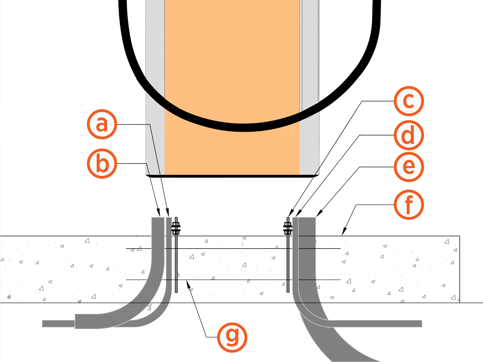
(a) (Optional) Shunt trip conduit: 19.1 mm (3/4 in trade size)
(b) AC conduit: 50.8 mm (2 in trade size)
(c) Anchor bolts
(d) Paired installations only: Ethernet conduit: 19.1 mm (3/4 in trade size)
(e) Paired installations only: DC conduit: 76.2 mm (3 in trade size)
(f) Concrete surface
(g) Concrete Mounting Template (embedded in concrete)
Depth of conduit or armored cable may vary by site. The image above does not dictate conduit depth, as long as the stub-ups are vertical and placed correctly.
Wiring Requirements for Standalone Stations
For full product specifications, refer to the Express 280 Datasheet. Using that data, ensure that the installation location is equipped with service wiring that supports the station's power requirements:
-
Neutral conductor as required by region (a Neutral connection is not required for equipment operation and the terminal is provided for convenience only)
-
Shunt trip wiring: size 0.08 to 2.5 mm² (28 to 14 AWG
 American Wire Gauge), fine stranded or solid
 -
AC conductors (L1, L2, L3) and ground per the following specifications:
|
Voltage Rating |
Temperature Rating |
Maximum Conductor Size for Terminals |
|---|---|---|
|
Phase conductors - 600 V |
90°C |
|
|
Ground conductor- 600 V |
90°C |
-
AC lugs (x3):
-
Silver plated copper compression lug (2-hole specified for North America); tin plated is acceptable if used with dielectric grease
-
Holes for an M6 (1/4 in) stud at 19 mm (3/4 in) stud hole spacing
-
Maximum width 30 mm (1.18 in)
Additional Wiring Requirements for Paired Stations
For stations that will be installed as Paired, follow all AC wiring requirements above as well as the following additional wiring.
Ethernet wiring for DC (paired stations only):
-
Minimum of CAT5e or better
-
Outdoor or plenum rated wiring
-
Maximum run length of 100 m (328 ft)
-
Leave 3.2 m (10.5 ft) of wire above grade at each end
-
Field crimp using straight-through pattern T-568B
DC conductors (x4):
-
2 positive and 2 negative conductors; 1 positive and 1 negative in each direction
-
Copper only, minimum current carrying capacity 200 A and 1000 V rated
-
DC cable run must be continuous. Do not splice DC cables
-
Consult site drawings for site-specific conductor size and length
-
Leave 61 cm (2 ft) of each conductor above grade at each end
|
Voltage Rating |
Temperature Rating |
Maximum Conductor Size for Terminals |
Insulation Type |
|---|---|---|---|
|
Phase conductors - 1000 V |
90°C |
300 kcmil, 1x per pole |
XHHW-2 |
|
Ground conductor- 1000 V |
90°C |
XHHW-2 |
DC lugs (x4):
-
All lugs must be nickel, tin, or silver plated copper compression (not mechanical) lugs
-
2-hole lugs, 1 in spacing, 3/8 in hole size, and 1.23 in max tongue width
When DC conductors are pulled through conduit, label each end of each DC conductor to aid installation as follows:
-
Station 1 A+ on one end and Station 2 B1+ on the other end
-
Station 1 A- on one end and Station 2 B1- on the other end
-
Station 1 B1+ on one end and Station 2 A+ on the other end
-
Station 1 B1- on one end and Station 2 A- on the other end

Wiring Diagram
General Notes
All equipment shall be installed and labelled in accordance with at least the 2017 national electrical code and all applicable requirements of the serving electric utility company and the authority having jurisdiction.
Underground conduit shall be schedule 40 PVC, except as noted otherwise on the drawing. Exposed conduit shall be EMT, ENT or RMC as required for the environment in which it is installed.
All conductors shall be copper. All OCPDS, conductors and conduit sizes stated here are provided by for reference only. Site specific wire sizing shall be performed by the installation contractor taking into account local conditions and codes/ standards. Use 90°c lugs to keep 's equipment thermal ratings.
Contractor shall perform GPR and take all necessary pre-cautions to work around existing utilities. All PPE shall be worn at all times while working around energized equipment. Contractor shall have appropriate license with state.
Sample single line shown. Single line may vary depending on project requirements and/or restrictions. Size wire according to site conditions and restrictions.
ChargePoint recommends right sizing the electrical gear, installing additional 's, and conduits for future EVSE![]() Electric Vehicle Supply Equipment stations and system expansion.
Electric Vehicle Supply Equipment stations and system expansion.
New Work Keynotes
Listing agency names and numbers to be indicated on all electrical equipment per NEC![]() National Electric Code 110.3(B).
National Electric Code 110.3(B).
Equipment may or may not be present in final design.
NEC![]() National Electric Code 625.43 disconnecting means: For equipment rated 60 A or more than 150 V to ground, disconnecting means shall be provided in accordance to NEC
National Electric Code 625.43 disconnecting means: For equipment rated 60 A or more than 150 V to ground, disconnecting means shall be provided in accordance to NEC![]() National Electric Code 110.22, 110.25, and 110.58.
National Electric Code 110.22, 110.25, and 110.58.
-
Listing agency names and numbers to be indicated on all electrical equipment per NEC
National Electric Code 110.3 -
Equipment may or may not be present in final design.
-
NEC
National Electric Code 625.43 disconnecting means: For equipment rated 60 A or more than 150 V to ground, disconnecting means shall be provided in accordance to NEC National Electric Code 110.22, 110.25, and 110.58.
|
Line Color |
Definitions |
|---|---|
|
|
480 VAC 3-PHASE CONDUCTORS |
|
|
ETHERNET COMMUNICATION CABLE (CAT6 SHIELDED TWISTED PAIR) |
|
|
200A, 600-1000 VDC +/- BUS A CONDUCTORS |
|
|
200A, 600-1000 VDC +/- BUS B CONDUCTORS |
|
|
CHARGING CABLES |

|
NEW EQUIPMENT |

|
FUTURE EQUIPMENT |

|
OPTIONAL SHUNT TRIP CONDUCTORS |

|
CELLULAR MODEM INSIDE PROVIDES NETWORK CLOUD CONNECTIVITY |


Definitions
-
CPE: ChargePoint Cpe280 Dispenser
-
DCS: Disconnect Switch where Required per NEC
National Electric Code 110.58 -
DP-EV
Electric Vehicle: Dedicated EVSE Electric Vehicle Supply Equipment Electrical Panelboard -
GND
Ground: Ground (Grounding Conductor) -
MAX: Maximum (Maximum Size Allowed)
-
MIN: Minimum (Minimum Size Allowed)
-
NEG: Negative (Negative DC Conductor)
-
POS: Positive (Positive DC Conductor)
-
STP
Shielded Twisted Pair: Shielded Twisted Pair
Each Express 280 requires a service panel breaker as follows:
|
Nominal Voltage |
Max AC Current |
Circuit Breaker Size |
|---|---|---|
|
480 VAC (NA) |
100 A |
125 A (125% continuous load required for North America) |
Typical Single Line Diagram

