Introduction
This section defines the purpose of this guide and provides an introduction to the ChargePoint® Express Distro Power Block 2000.
About This Guide
This guide provides instructions for installing the Power Block 2000. It covers preparation requirements, mounting and anchoring procedures, electrical and communication connections, commissioning steps, and verification tasks needed to place the station into service.
This guide is intended for licensed electricians, installation contractors, and construction professionals responsible for installing Power Block 2000 equipment in accordance with local codes and ChargePoint requirements.
This edition of the guide focuses on installing Power Block 2000 in the single‑cabinet, four‑output configuration. Support for double‑ and triple‑cabinet installations, along with eight‑output and twelve‑output configurations, will be incorporated in a later update.
Power Block 2000 Overview
Power Block 2000 is a product within the ChargePoint Express DC fast charging platform. Power Block 2000 is a power cabinet, responsible for AC grid connection, power conversion, and DC power distribution to downstream EVSEs such as external Power Link charging dispensers.
For information on Power Link charging dispensers and other EVSEs in the ChargePoint Express platform, refer to the Express platform documents at ChargePoint Product Reference Documentation.
Exterior Parts
The following shows an exterior view of a single-cabinet Power Block 2000:
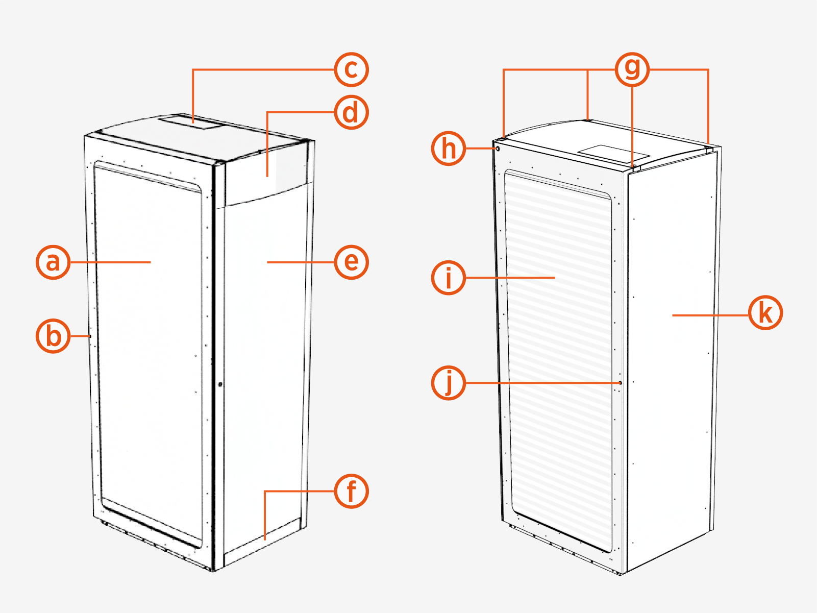
|
Ref |
Part |
Ref | Part |
|---|---|---|---|
| (a) |
Exhaust (left) door with airflow vents |
(g) |
Lifting points |
| (b) |
Exhaust door lock |
(h) |
Status LED |
| (c) | Smart Antenna (optional) | (i) |
Intake (right) door with airflow vents |
| (d) |
Logo plate (customizable) |
(j) |
Intake door lock |
| (e) |
Front panel (with customizable vinyl) |
(k) |
Rear panel |
| (f) |
Front bottom plate |
Cabinet Configurations
Power Block 2000 is available in single-, double-, or triple-cabinet configurations, as shown below. The double- and triple-cabinet models ship as a single integrated unit, with the cabinets factory‑bolted together.
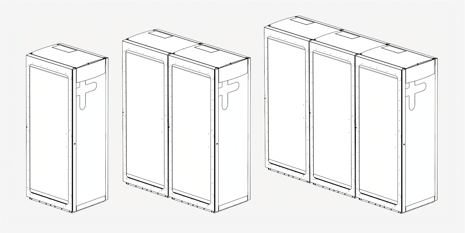
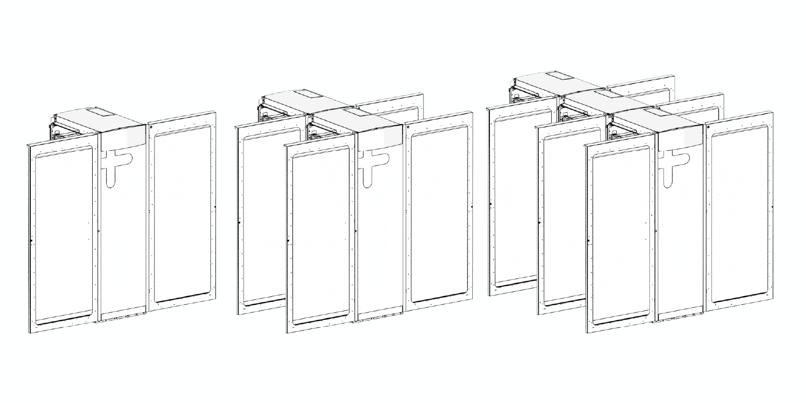
The side doors for each cabinet section swing open towards the front of the unit.
Interior Parts
The following shows the interior views of the single-cabinet Power Block 2000:
|
|
|
| Intake (Right) Side | Exhaust (Left) Side |
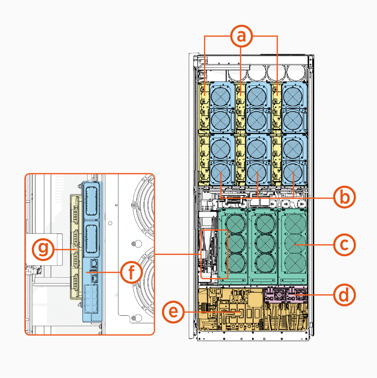
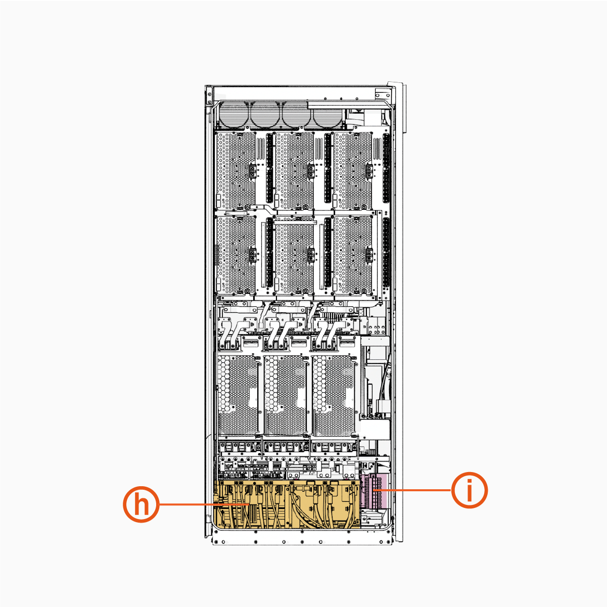
|
Ref |
Part |
Ref | Part |
|---|---|---|---|
| (a) |
Contactor matrix |
(f) |
Power Management Controller (PMC) |
| (b) |
DC power modules |
(g) |
Safety Hub Board (SHB) |
| (c) |
AC power modules |
(h) |
Wire terminals and bus bars, exhaust side |
| (d) |
Aux power supply (AUX PS |
(i) |
48 V DC fuse block |
| (e) |
Wire terminals and bus bars, intake side |
|
The interior parts shown above are present in each cabinet of the double- and triple-cabinet Power Block 2000.
System Description
The Power Block 2000 intakes 3-phase AC grid power and performs power conversion with two types of modules:
-
AC Power Module – The AC power module converts AC input power to DC output power. Up to three modules can be installed into each Power Block 2000 cabinet to scale total power capacity.
-
DC Power Module – The DC power module is an isolated, bidirectional DC/DC converter that conditions power for delivery to downstream EVs.
The Power Block 2000 has two separate DC power distribution buses:
-
DC Grid Bus – The DC Grid Bus is a non‑isolated DC bus (up to 950 V depending on region and application). Multi-cabinet Power Block 2000s can ship with their DC Grid Buses interconnected for power sharing. DC Grid functionality is supported only on 480 V AC and 400 V AC Power Block 2000 models; 600 V AC models do not support DC Grid.
-
DC Output Bus – The DC Output Bus is an isolated DC bus (100–1000 V) that delivers regulated output power to connected EVs. Power flow from the DC Output Bus is routed through the Contactor Matrix, which selectively connects to a set of discrete external DC outputs.
The Power Block provides the following external DC outputs:
-
Power Block 2000 is available with four, eight, or twelve external DC outputs per cabinet, designated EXT A, EXT B, EXT C, and so on through EXT L.
-
Each output can supply power to a single input power path of a Power Link charging dispenser.
The Power Block 2000 is equipped with an Auxiliary Power Supply (APS) system:
-
Auxiliary Power Supply (AUX PS
 Auxilary Power Supply) Modules – Each cabinet includes AUX PS Auxilary Power Supply modules that generate 48 V DC power for internal electronics and sub-assemblies within the unit.
 -
48 V DC Output – Each Power Block 2000 cabinet provides 48 V DC outputs for supplying power to connected Power Link charging dispensers.
The Power Block 2000 features an integrated system that facilitates safe and reliable communication and control:
-
Power Management Controller (PMC) – The PMC controls power flow within the system. It communicates with the power converters and the contactor matrix to manage the delivery of power to the external DC outputs. The PMC supports Ethernet ports for communication with various components like connected Power Link charging dispensers and interconnected Power Block 2000 cabinets to ensure seamless operation. In the event of a fault, the PMC can instruct the power converters to stop power delivery and open the contactors to isolate the power source.
-
Contactor Matrix – The contactor matrix receives commands from the PMC to open or close the contactors as needed.
-
Safety Hub Board (SHB) – In addition to processing fault reports from the Neutron, the SHB supports four dispenser ports for performing continuous electrical isolation monitoring of connected Power Link charging dispensers. Any faults detected are reported to the PMC.
System Interfaces and Sample Architecture
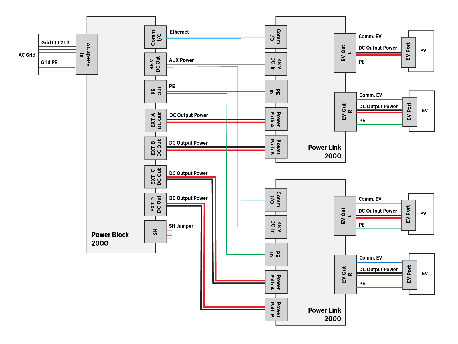
The following provides a high-level overview of the electrical interfaces of a Power Block 2000. The diagram also illustrates the interconnections required for an example architecture in which the Power Block 2000 provides DC output power to the input power paths (A and B) of two Power Link 2000s. The Power Link 2000s are each equipped with two charging cables (L and R). Note that Power Link 2000 does not require Safety Hub (SH) monitoring.
Product Guides
A full suite of guides is available for Power Block 2000, as summarized below.
|
Document |
Content |
Primary Audiences |
|
Datasheet |
Full station specifications |
Site designer, installer, and station owner |
|
Site Design Guide |
Civil, mechanical, and electrical guidelines to scope and construct the site |
Site designer, responsible engineer, contractors, installers |
|
Construction Signoff Form |
Checklists used by contractors to ensure the site is correctly completed and ready for product installation |
Site construction contractor |
|
Installation Guide |
Anchoring, wiring, and powering on |
Installer |
|
Operation and Maintenance Guide |
Operation and preventive maintenance information |
Station owner, facility manager, and technician |
|
Service Guide |
Component replacement procedures, including optional components |
Service technician |
|
Declaration of Conformity |
Statement of conformity with directives |
Purchasers and public |
Access ChargePoint documents at ChargePoint Product Reference Documentation.
