Mount Power Block 2000
Follow all instructions provided in this section to mount the Power Block 2000.
Wire Entry Overview
Below is a sample depiction of Power Block 2000 wire entry via conduit stub-ups. In regions that do not use conduits and/or use armored cables, the cables shall be laid out in a similar pattern.
The size and quantity of conduits and wires shown below are for illustrative purposes only. The actual quantity and size of conduits and wires for your specific site may vary and shall depend on site specific requirements.
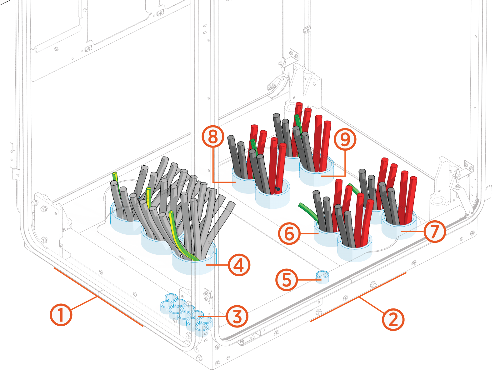
(1) Cabinet front side
(2) Cabinet intake (right) side
(3) 48 V DC, Ethernet, and Safety Hub
(4) AC input
(5) Shunt trip
(6) EXT A
(7) EXT B
(8) EXT C
(9) EXT D
To view wire landing locations within the cabinet, see Wire Terminal and Bus Bar Locations.
Cable Jigs Overview
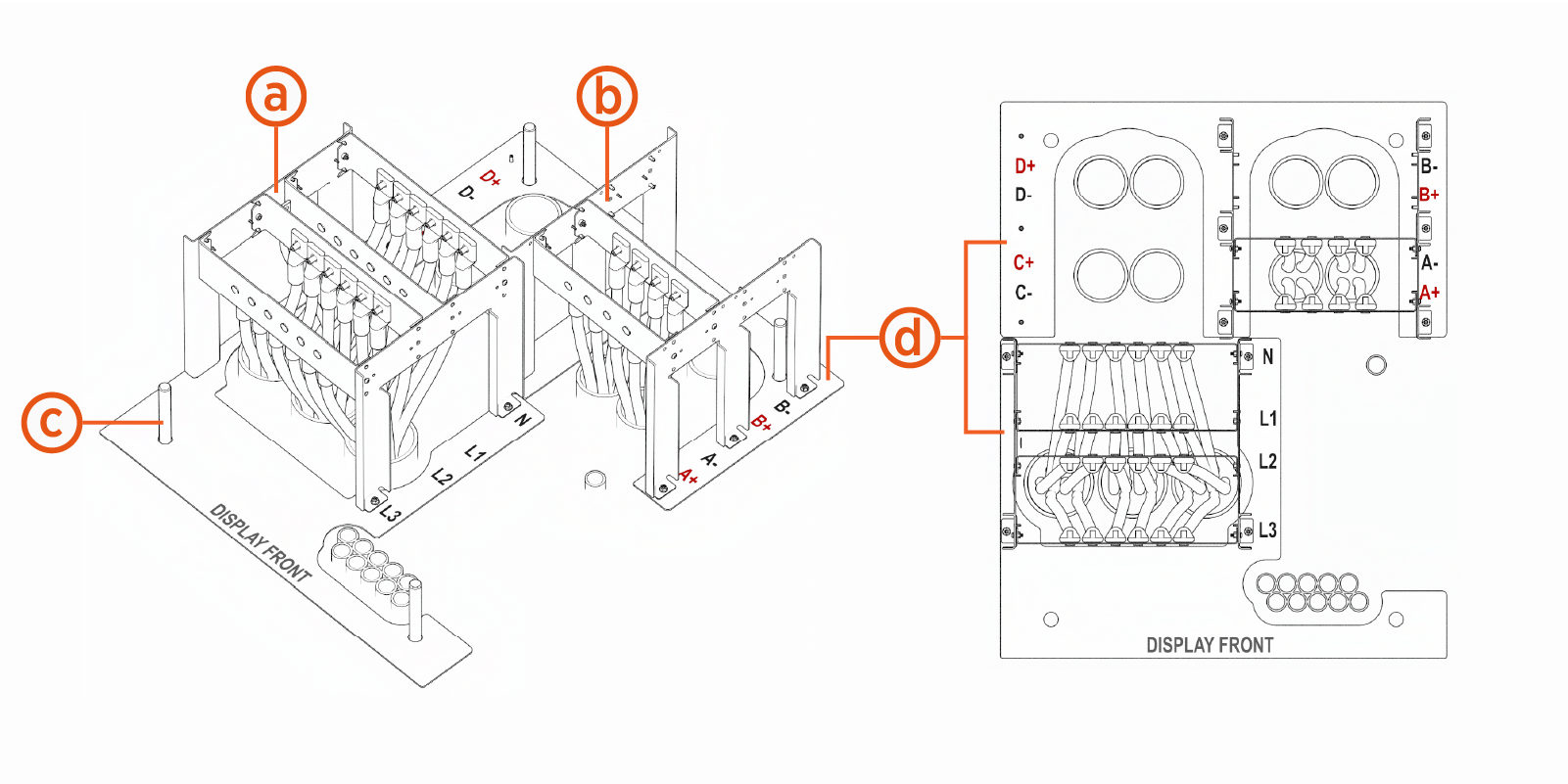
The AC input and external DC output wires must be pulled through conduit and prepared for connection using two cable jigs. The cable jigs replicate the positions of the bus bars within the Power Block 2000 cabinet and allows the wires to be prepared (cut to correct length and positioned correctly) before the station is positioned and secured to the concrete pad.
The size and quantity of conduits and wires shown below are for illustrative purposes only. The actual quantity and size of conduits and wires for your specific site may vary and shall depend on site specific requirements. Use the diagram solely to review usage of the cable jigs.
|
Ref |
Part |
Function or Definition |
|---|---|---|
| (a) |
DC cable landing jig |
Positions the external DC output wires for landing on bus bars |
| (b) |
AC input cable landing jig |
Positions AC input wires for landing on bus bars |
| (c) |
Anchor bolt |
Concrete-embedded anchor bolts (x4) |
| (d) |
Jig alignment plate |
Two-part plate that installs over the anchor bolts and serves as a base for the cable jigs |
Pull and Test AC Input and External DC Output Wires
Follow the procedure below to pull and test AC input and external DC output wires.
-
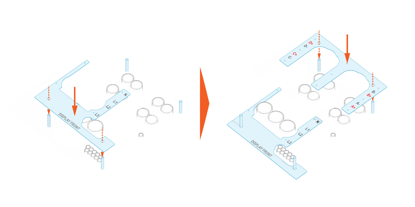
Install the jig alignment plates over the anchor bolts and conduit stub-ups.
The size and quantity of conduits and wires shown below are for illustrative purposes only. The actual quantity and size of conduits and wires for your specific site may vary and shall depend on site specific requirements. Use the diagram solely to review usage of the cable jigs.
-
Power Block 2000 supports four different conduit options. Study the line diagram carefully to understand which wires should be pulled through each conduit.
-
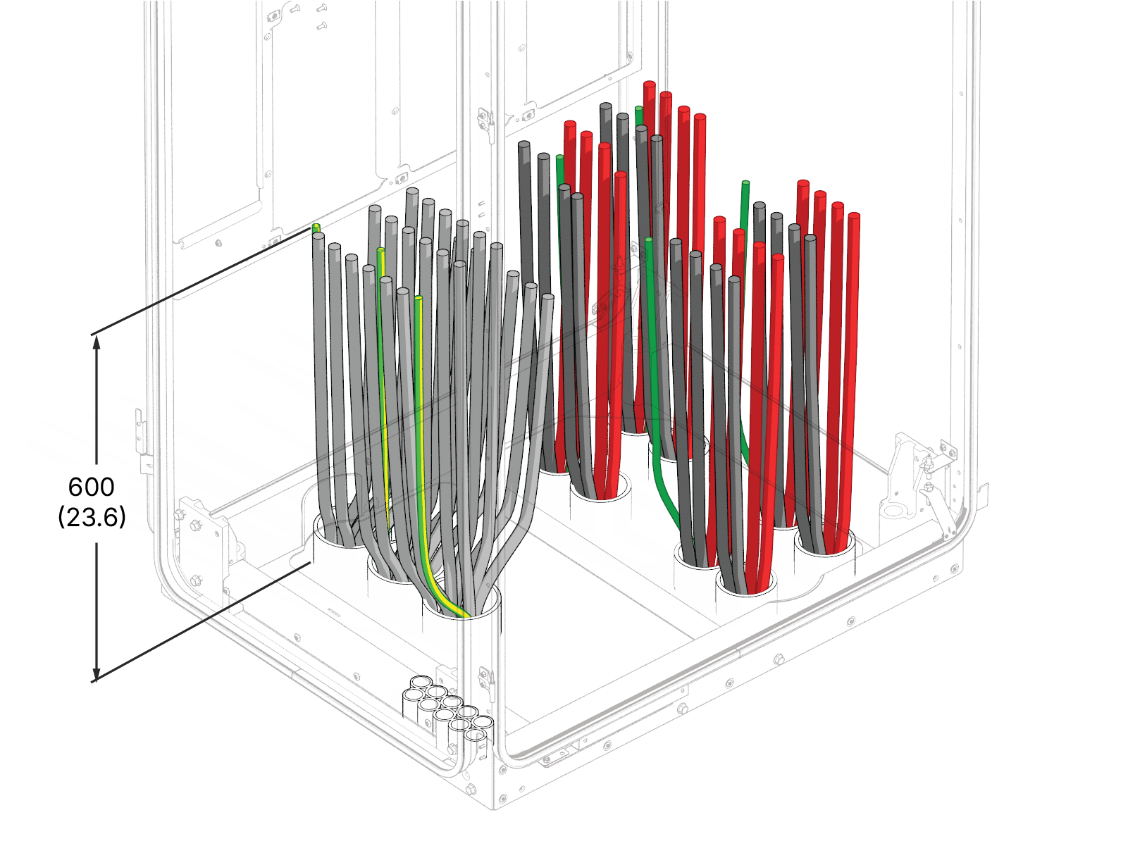
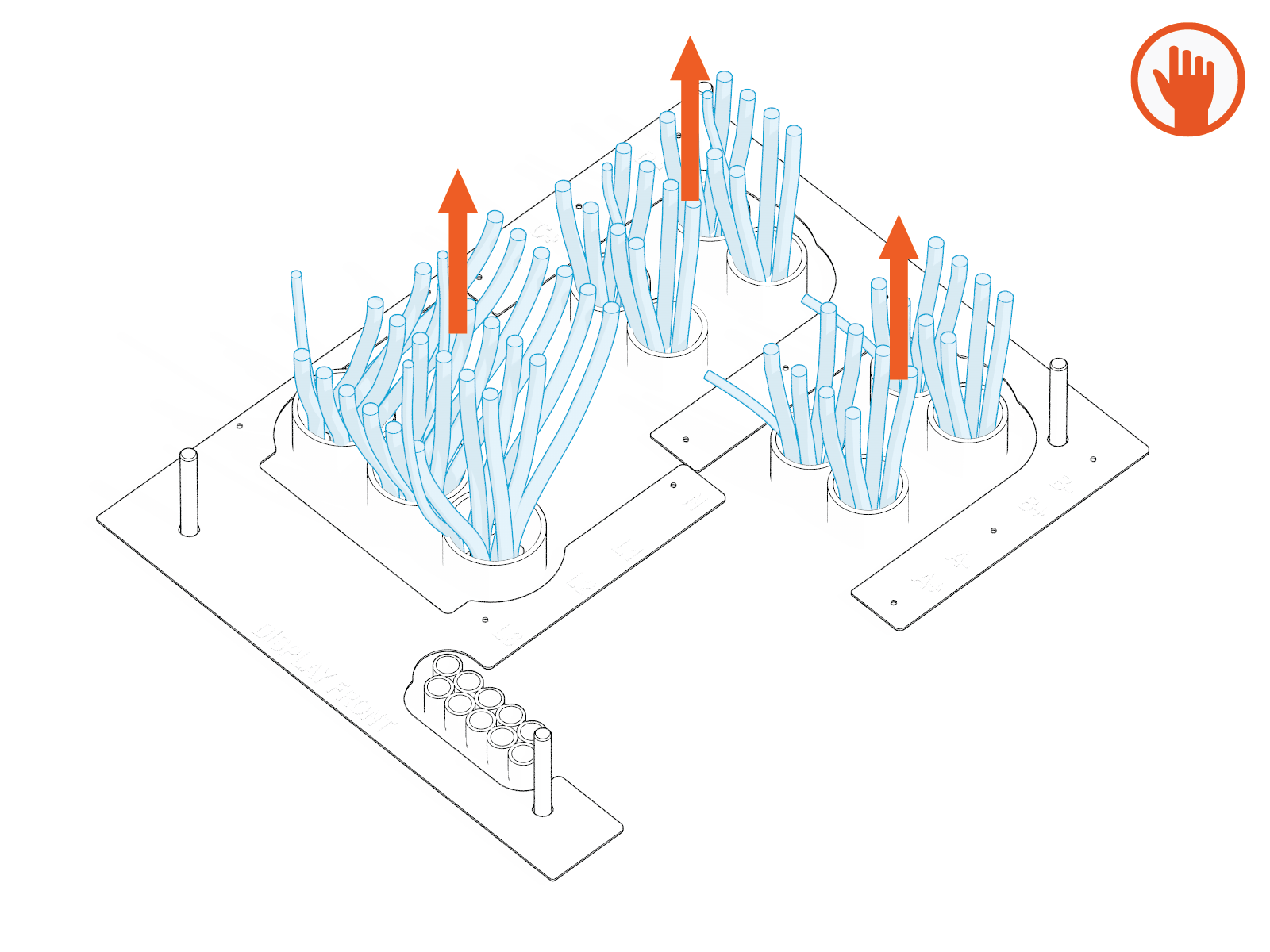
Prepare wires for conduit pull. Label each wire at both ends. Plan wire lengths so that, after pulling, there is sufficient wire length to land on all lug landing positions on the cable jig. Alternatively, plan for wires to extend a minimum of 600 mm (23.6 in) above the finished mounting surface.
-
Pull the AC input and External DC output wires through conduit. If necessary, apply a non-conductive wire pulling lubricant.
-
Perform insulation resistance test on the pulled wires. Refer to the High Voltage Wire Insulation Resistance Test Field Guide.
-
Wipe off any remains of wire pulling lubricant (if applied).
Prepare AC Input Wires
Follow steps below to prepare AC input wires using the AC input cable landing jig.
-
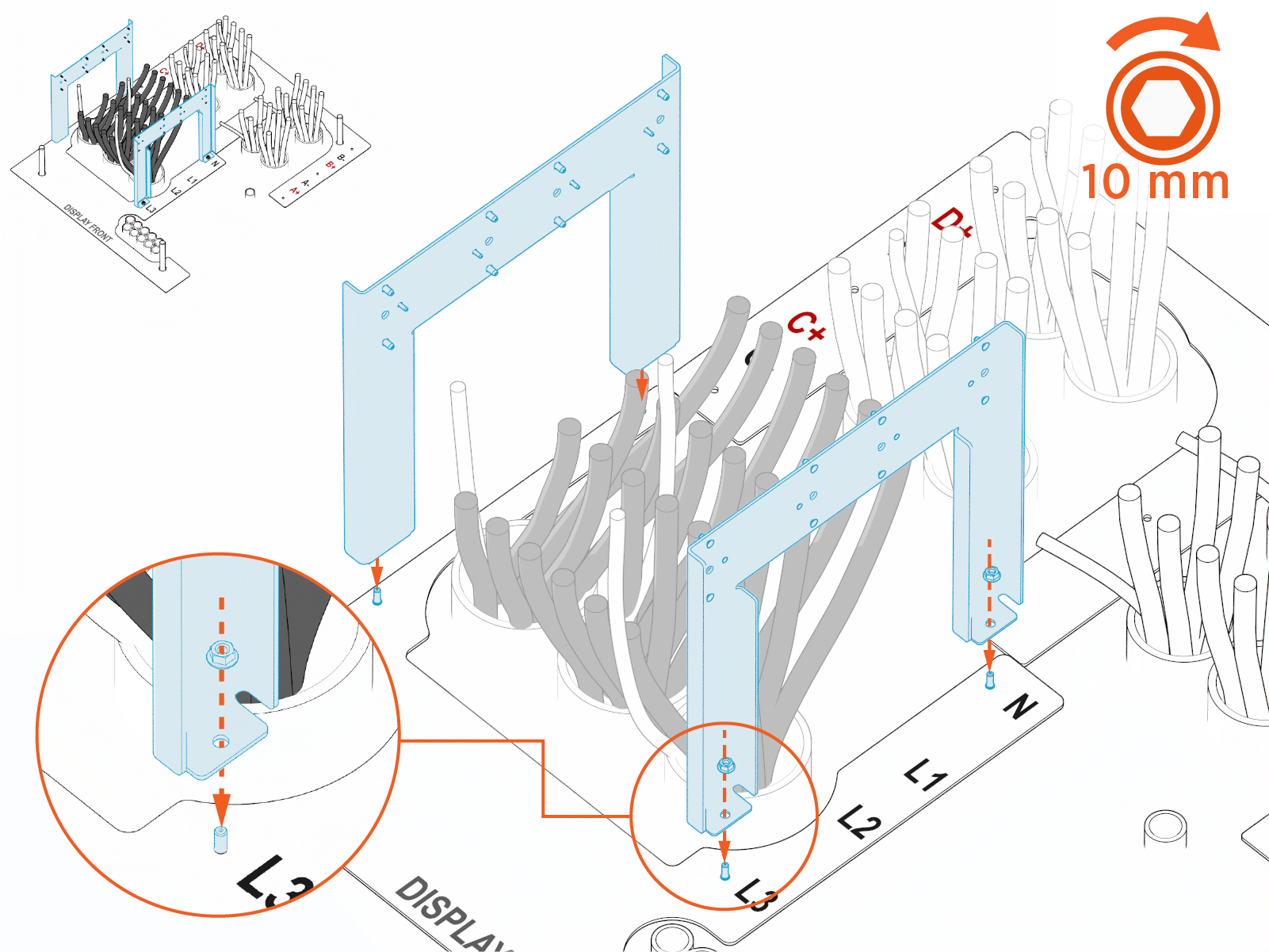
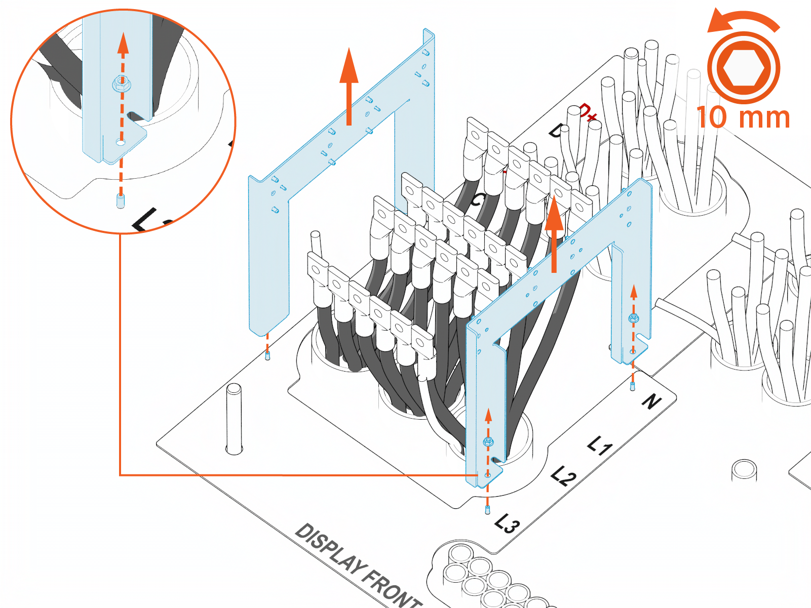
Secure each side frames (x2) to the jig alignment plate using provided M6 hex nuts (x2 for each frame). Torque to 5.6 Nm (50 in-lb).
-
If neutral is required, take the following steps to prepare the neutral wires:
-
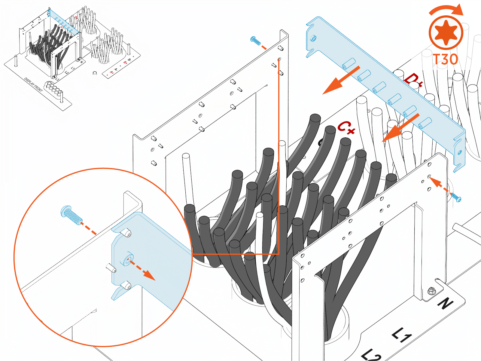
Attach the stud landing bar to the side frame in the neutral (N) position. Secure the bar with provided M6 bolts (x2).
-
Install the wire lugs on the stud landing bar. Secure each lug with provided M10 hex nut. Hand tighten.
IMPORTANT: Ensure all wire lugs are installed vertically on the landings studs, with no tilt or skew.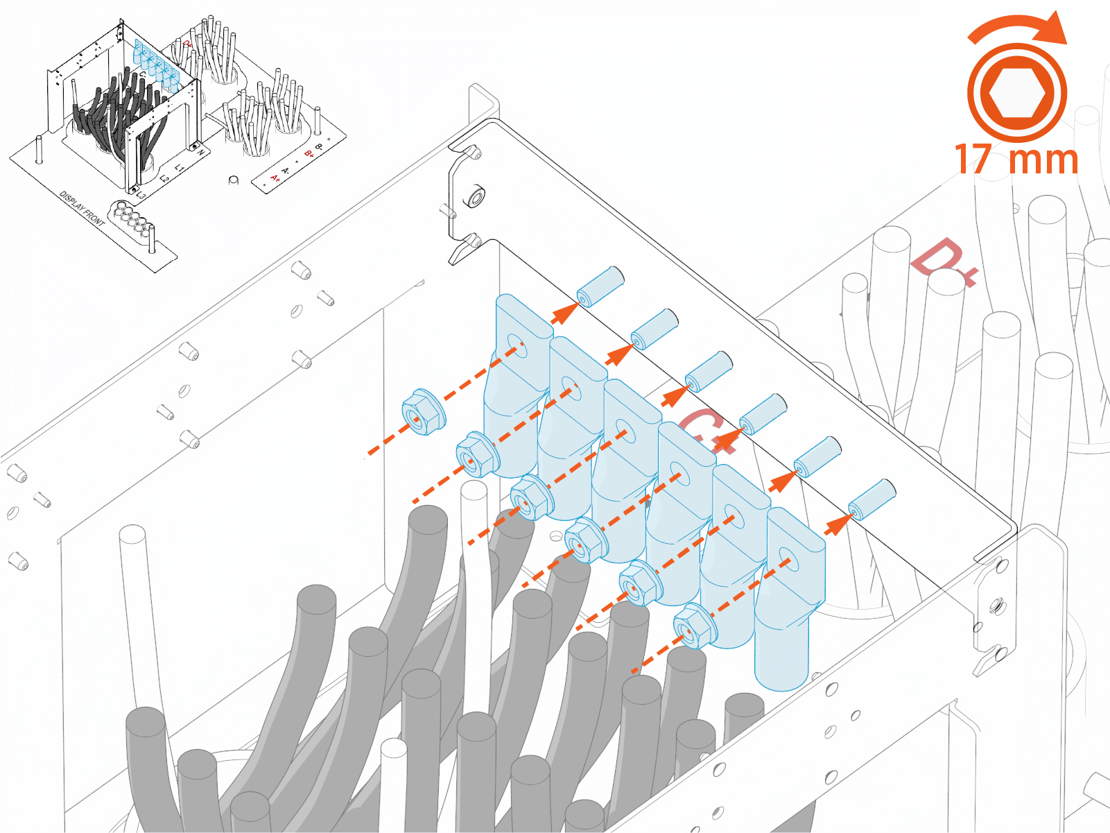
-
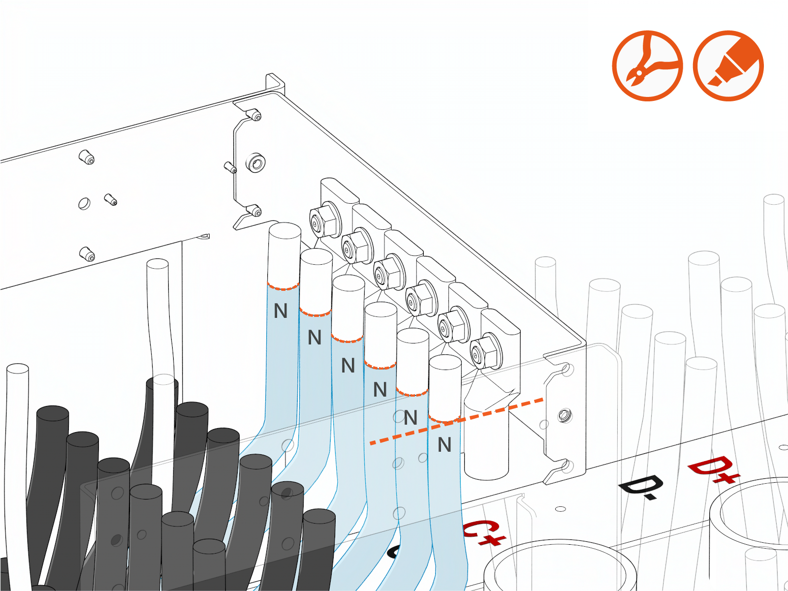
Position the neutral wires next to the lugs. Mark and cut the wires to length.
-
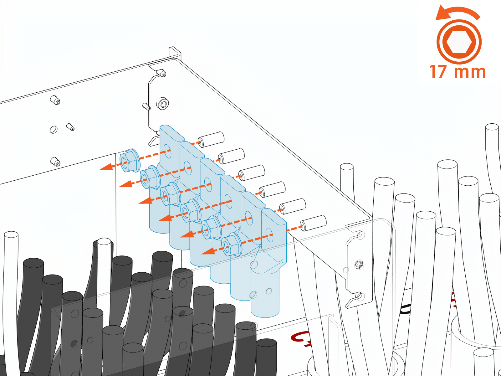
Remove the lugs from the stud landing bar.
-
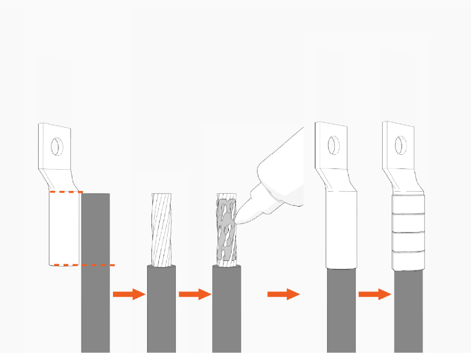
Terminate each wire with a lug:
-
Mark the lug's barrel height on the cable.
-
Strip the wire jacket. Use a suitable wire stripper, such as a Klein tool.
-
If recommended by the wire manufacturer or local code, apply an anti-oxidant joint compound to the bare cable to make a gastight joint with the lug.
-
Insert the stripped wire end into the lug barrel and crimp it. Use a suitable lug crimping tool and/or die recommended by the lug manufacturer.
-
-
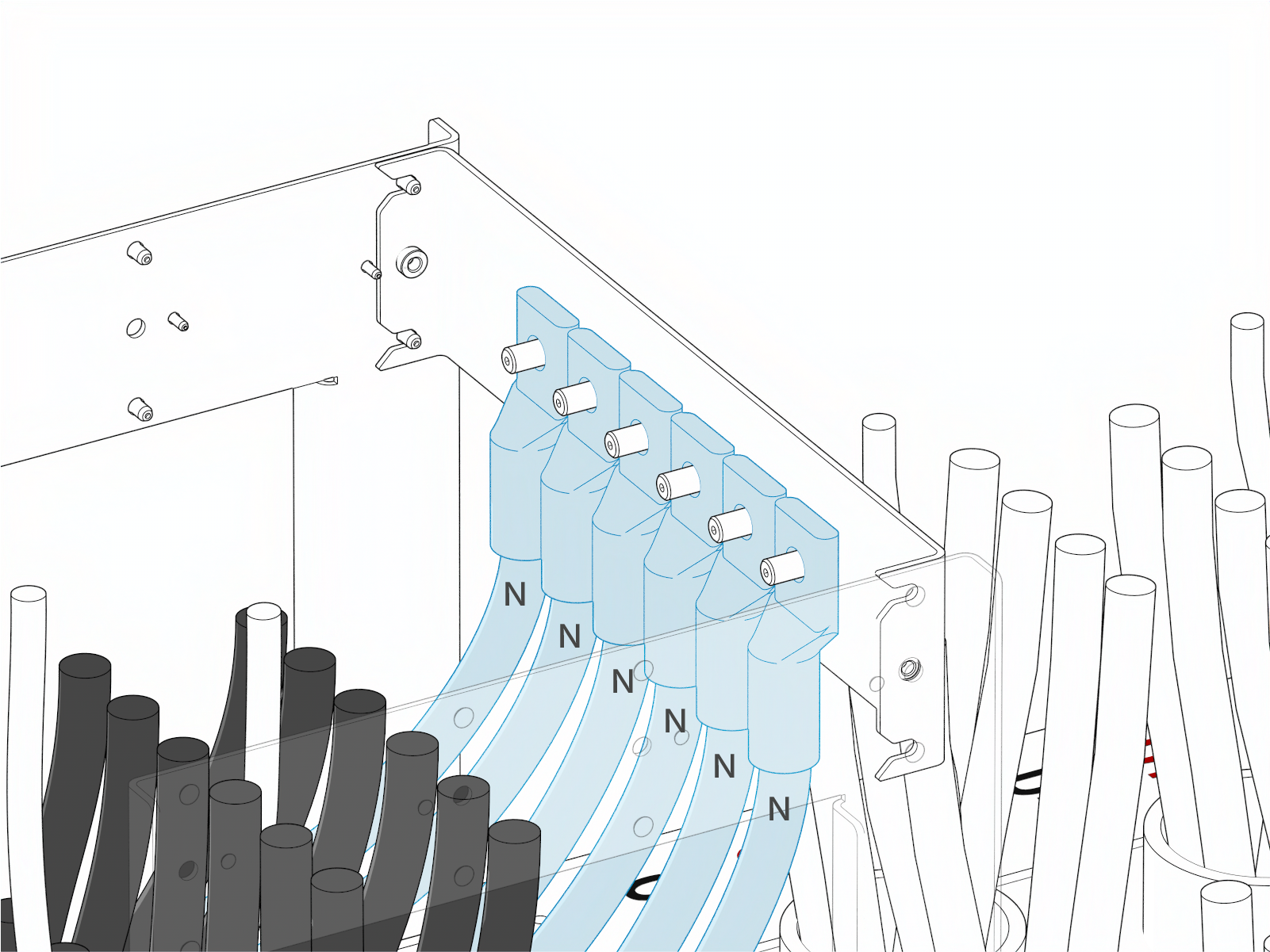
Stage the terminated wires on the stud landing bar.
-
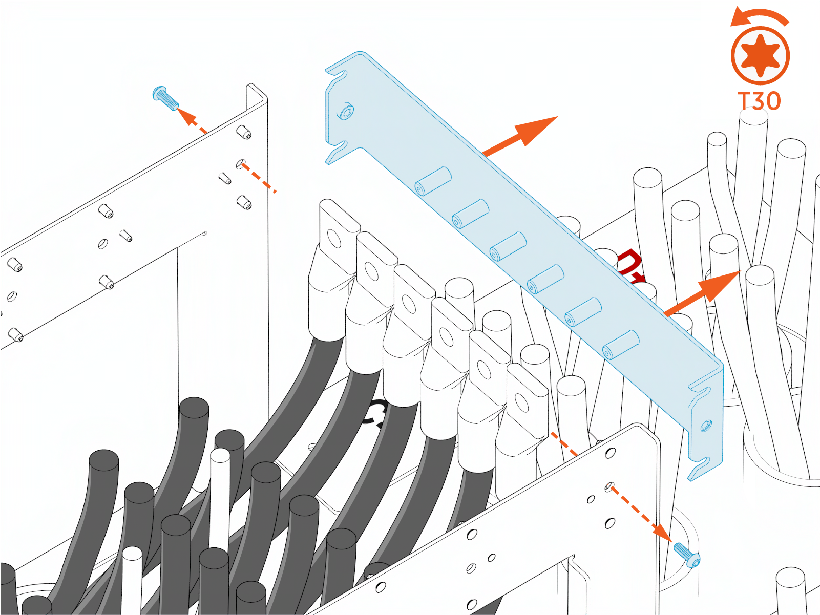
Unfasten stud landing bar and slide it out to the side.
-
-
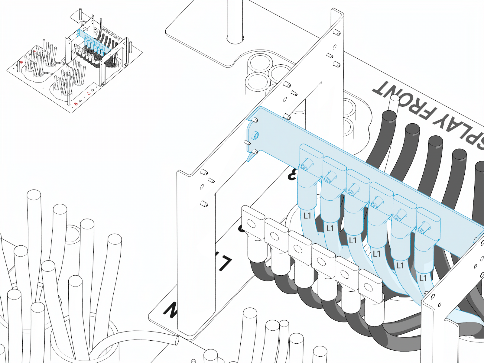
Repeat to stage the L1 wires.
-
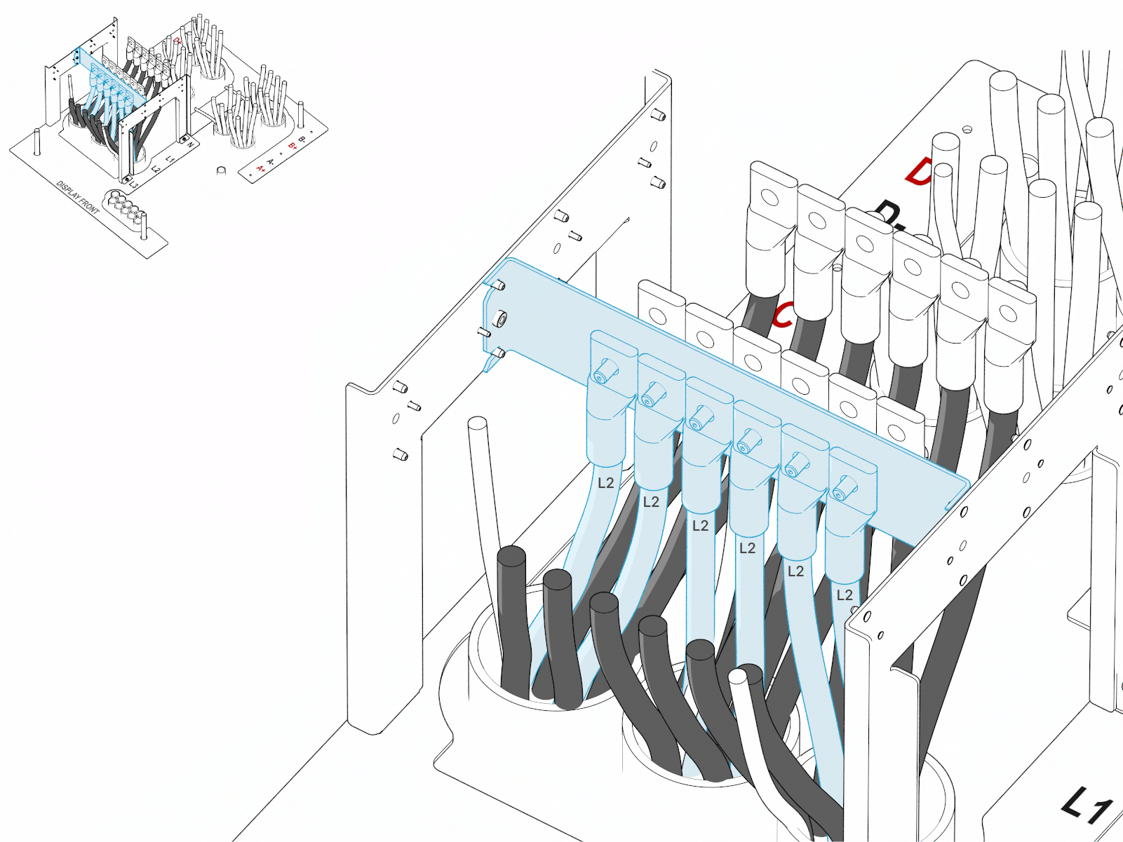
Repeat to stage the L2 wires.
-
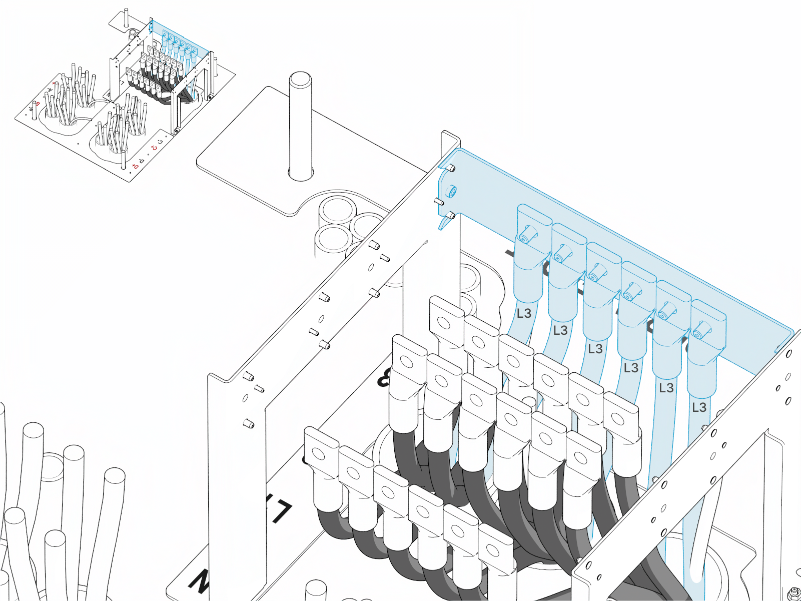
Repeat to stage the L3 wires.
-
Unfasten and remove the side frames from the jig alignment plate.
Prepare External DC Output Cables
Follow steps below to prepare the external DC output wires using the DC cable landing jig.
-
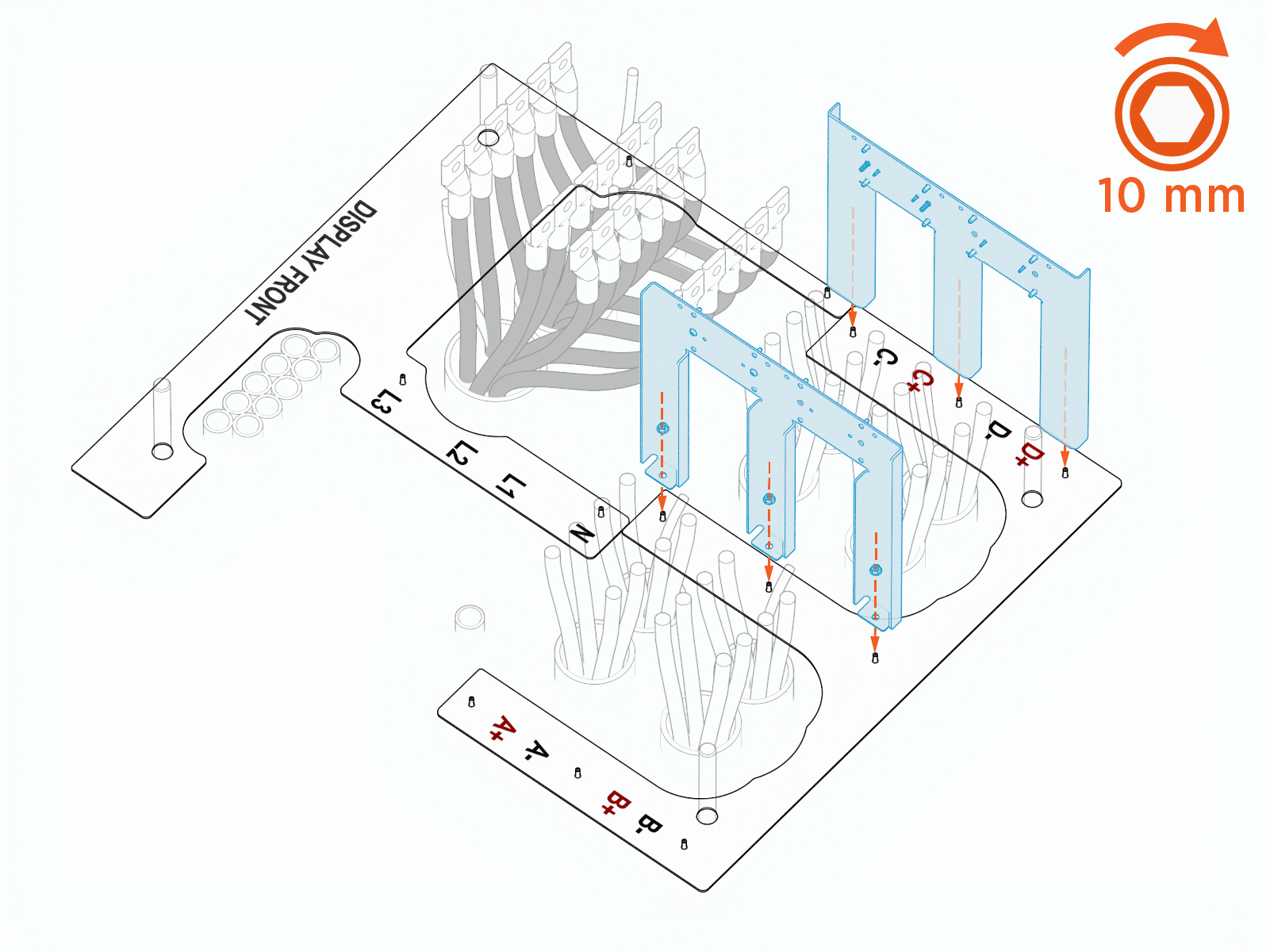
Install the side frames (x2) around the exhaust-side external DC output conduits. Secure them to the jig alignment plate using provided M6 hex nuts (x3 for each frame). Torque to 5.6 Nm (50 in-lb).
-
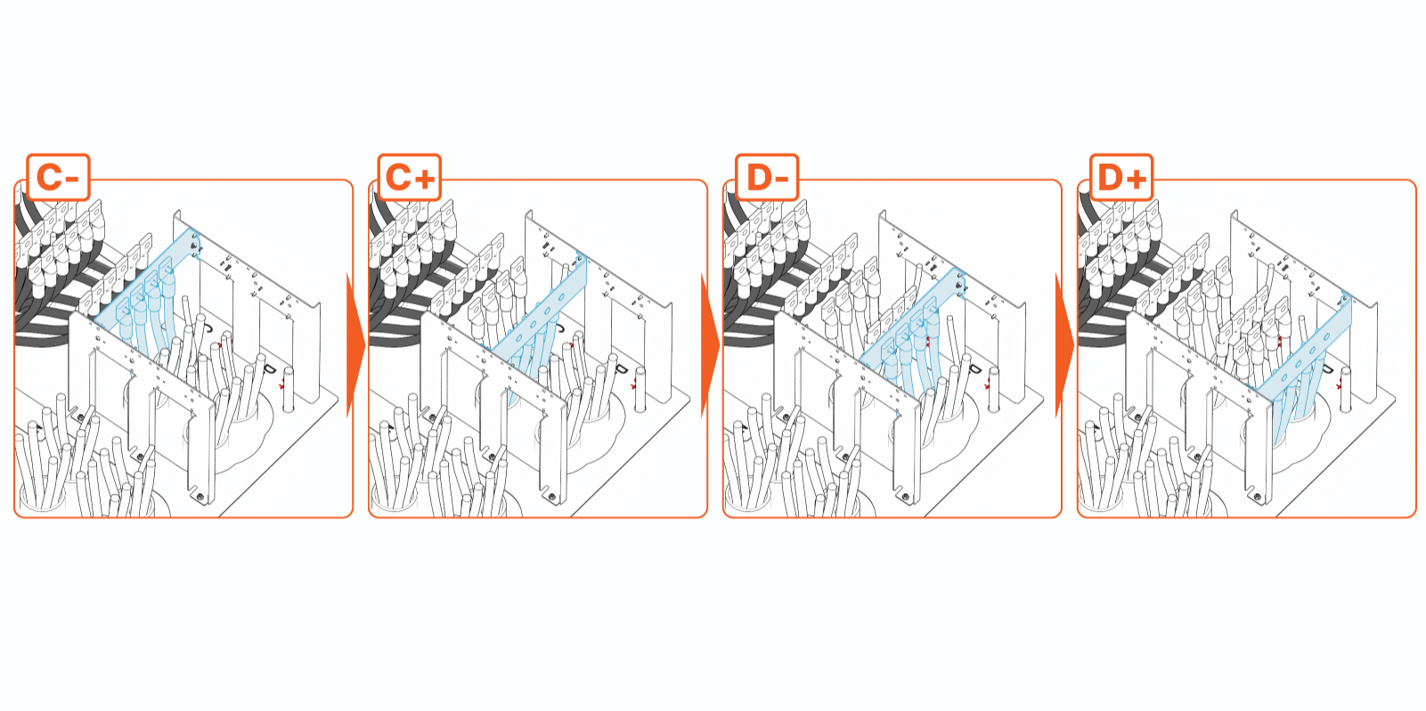
Using the same procedure described for the AC cable jig, cut, terminate, and stage the EXT C negative (C-), EXT C positive (C+), EXT D negative (D-), and EXT D positive (D+) wires, working one row at a time. Remove the cable jig when done.
-
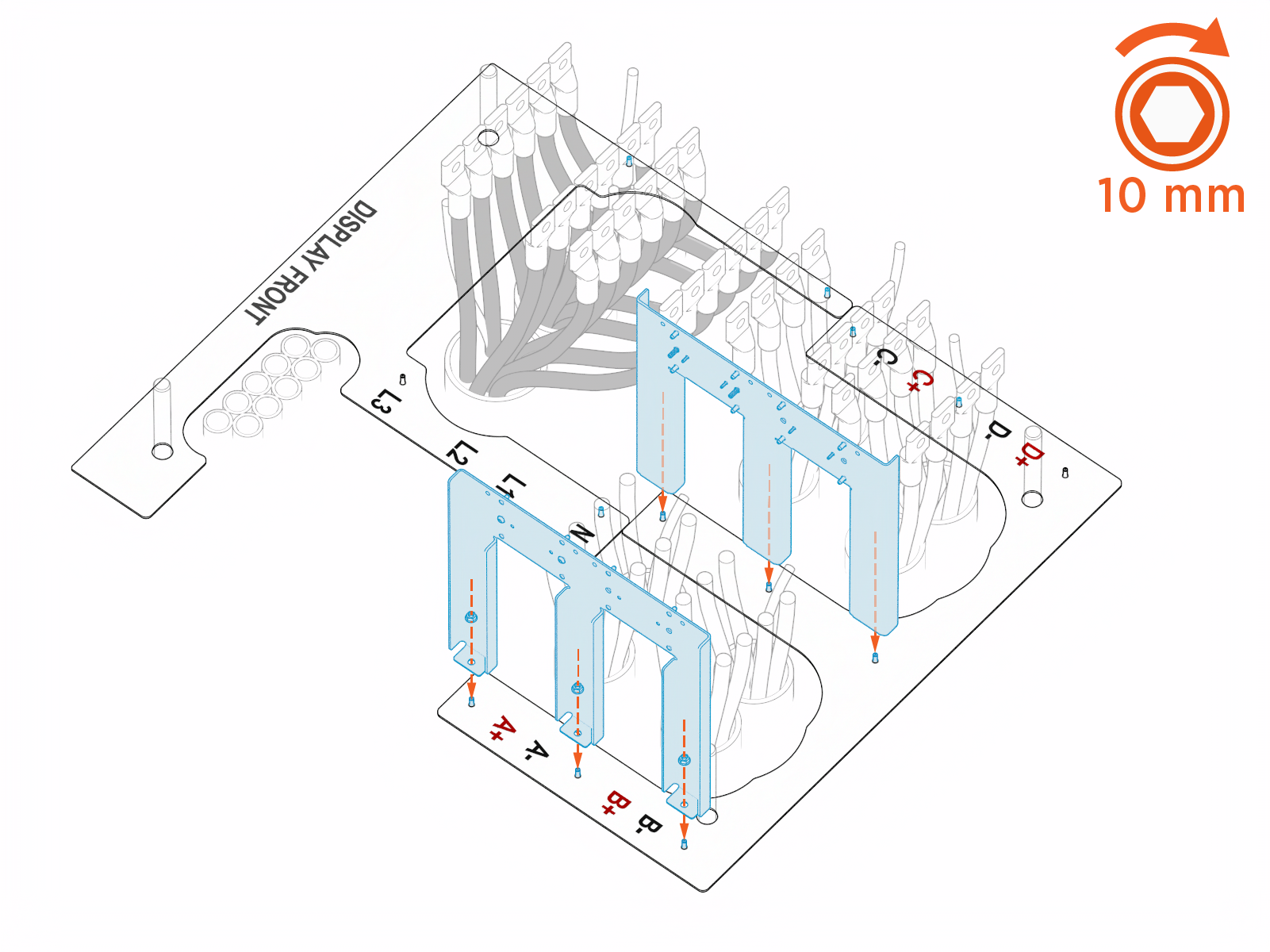
Install the side frames (x2) around the intake-side external DC output conduits. Secure them to the jig alignment plate using provided M6 hex nuts (x3 for each frame). Torque to 5.6 Nm (50 in-lb).
-
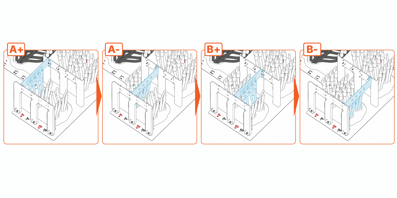
Working one row at a time, use the stud landing bar to prepare the EXT A positive (A+), EXT A negative (A-), EXT B positive (B+), and EXT B negative (B-) wires.
-
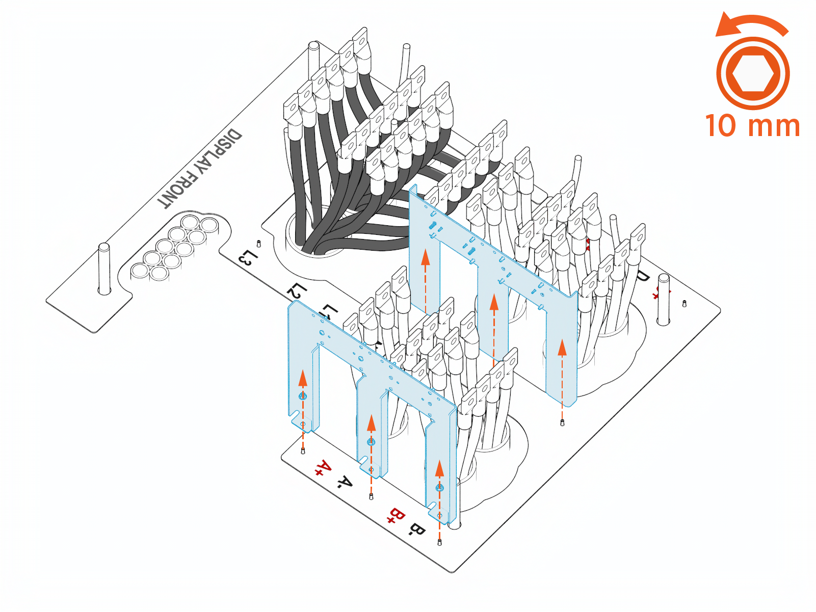
Remove the DC cable jig.
Finalize Wire Preparation
-
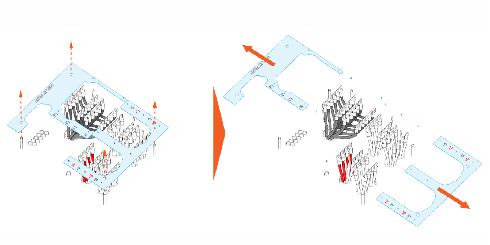
Remove the jig alignment plates. Lift each jig alignment plate off the anchor bolts and move it away from the installation area.
-
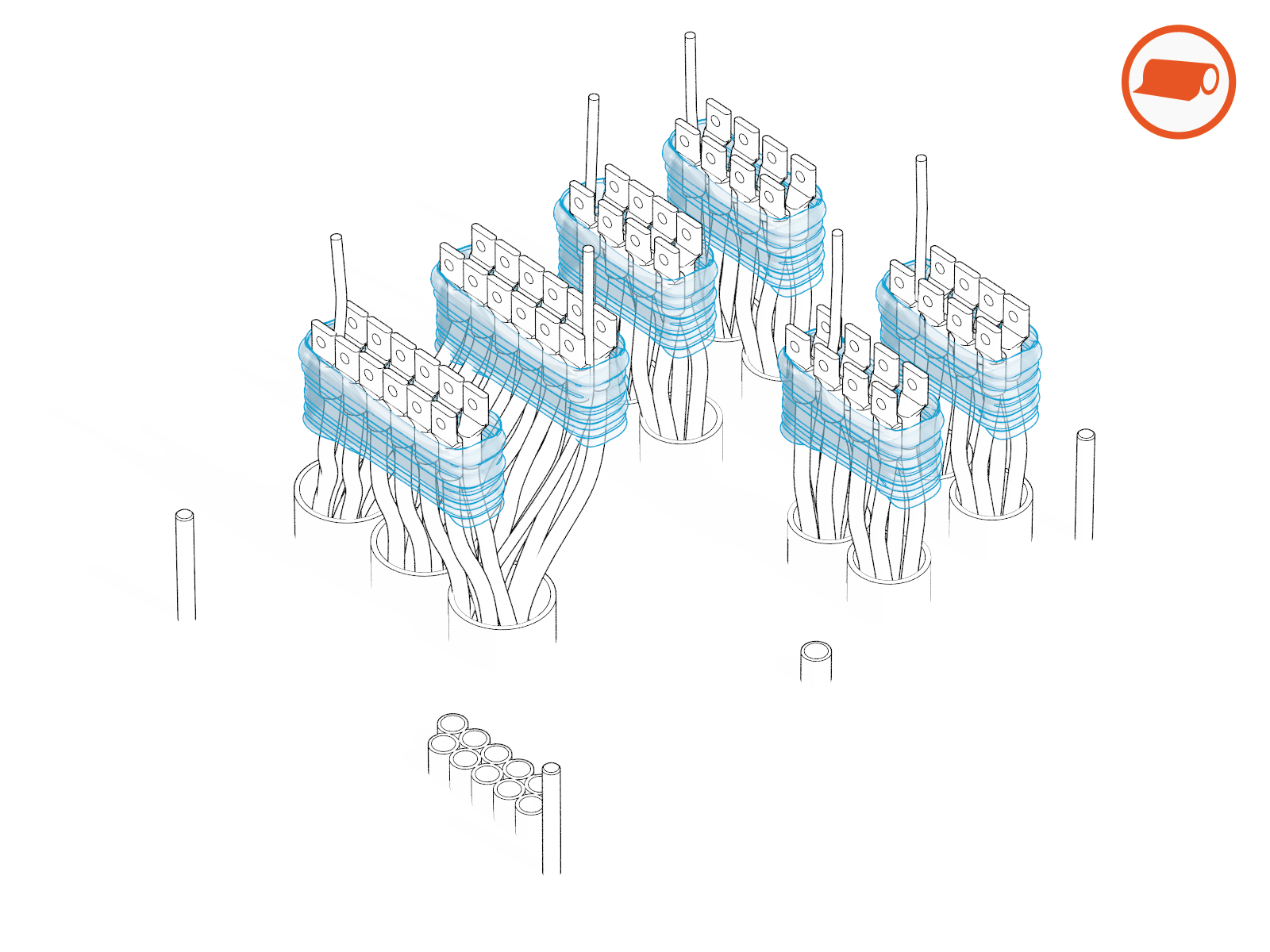
Use cling film to carefully bundle the wires as shown below. The un-terminated ground/PE wires may be gathered within the wire bundles.
Open Doors and Remove Safety Covers
Follow steps below to open the intake and exhaust doors and remove bus bar safety covers.
-
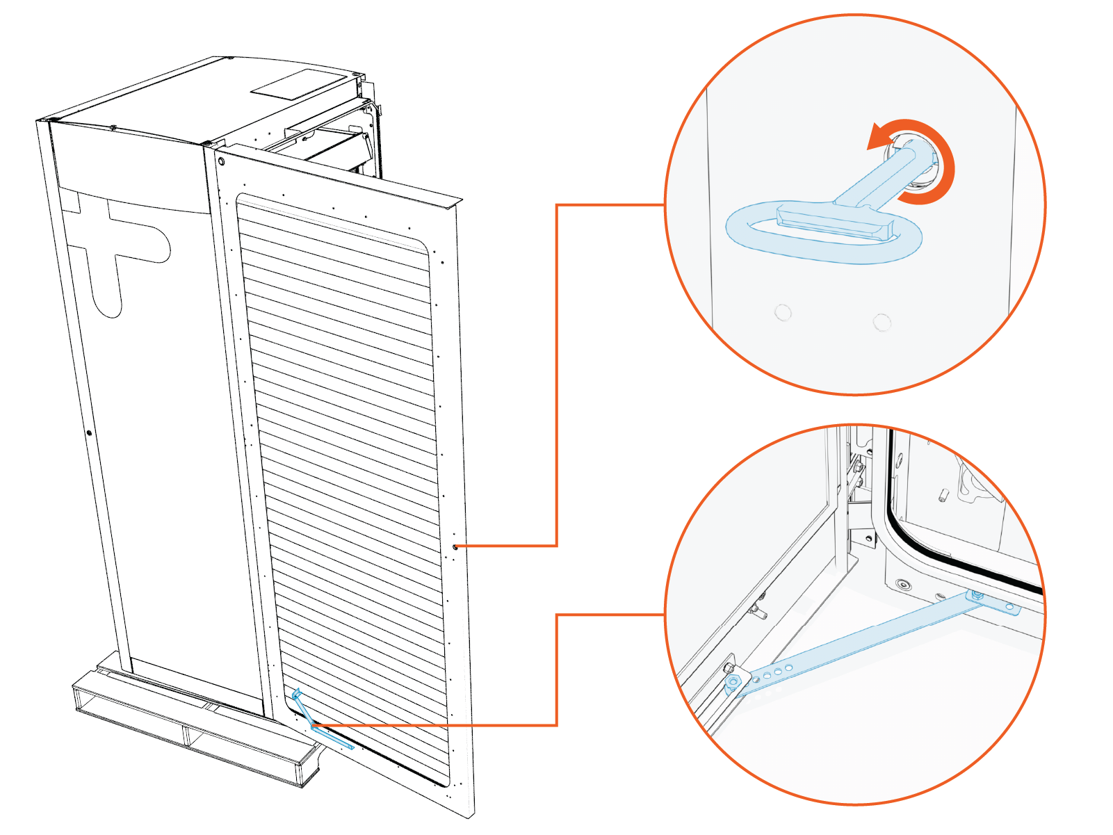
Use the door key to unlock the intake (right side) door. Swing the exhaust door open until the door stopper holds the door in open position.
-
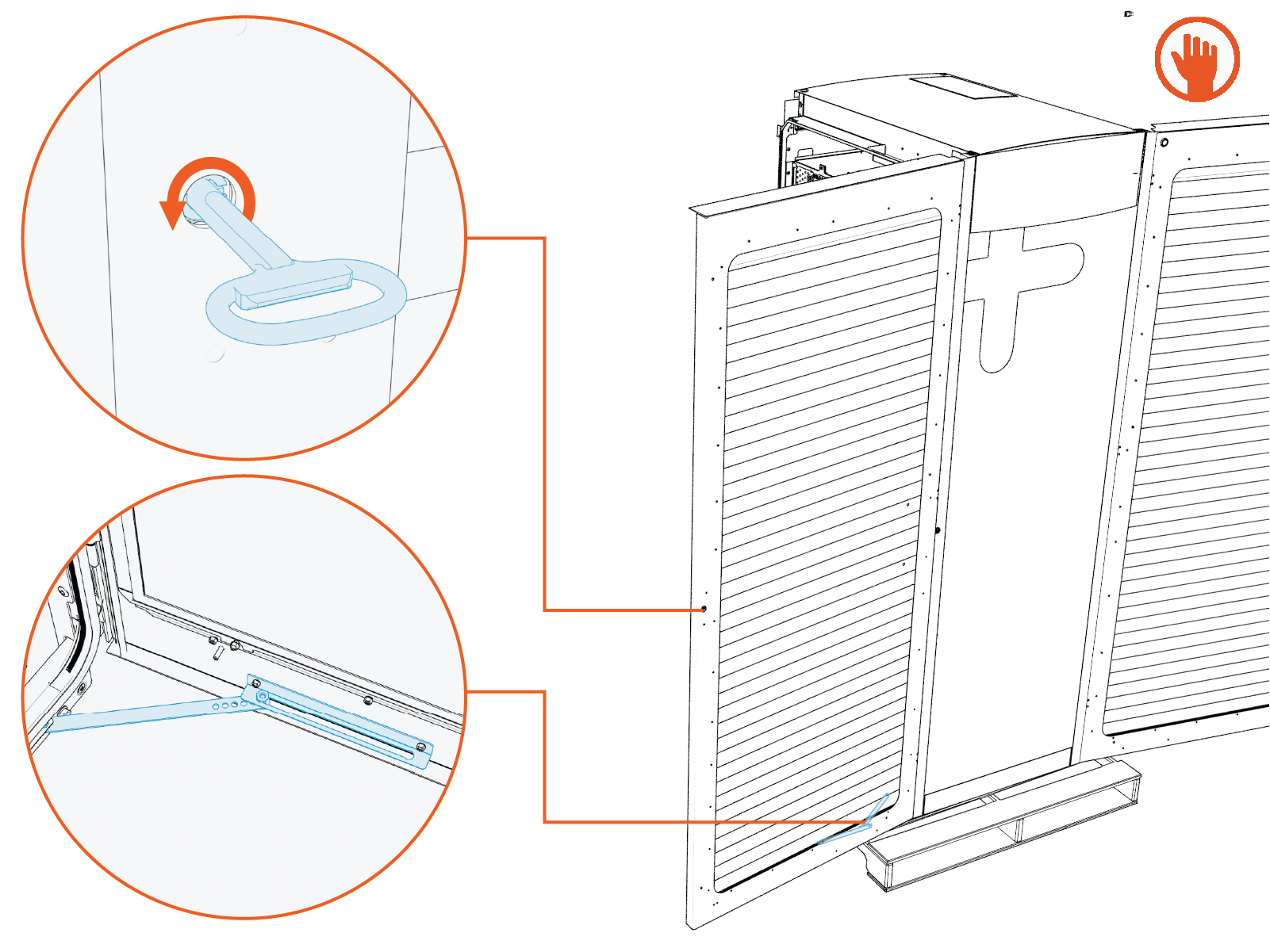
Open the exhaust (left side) door in the same manner. Make sure the door stopper holds the door in open position.
-
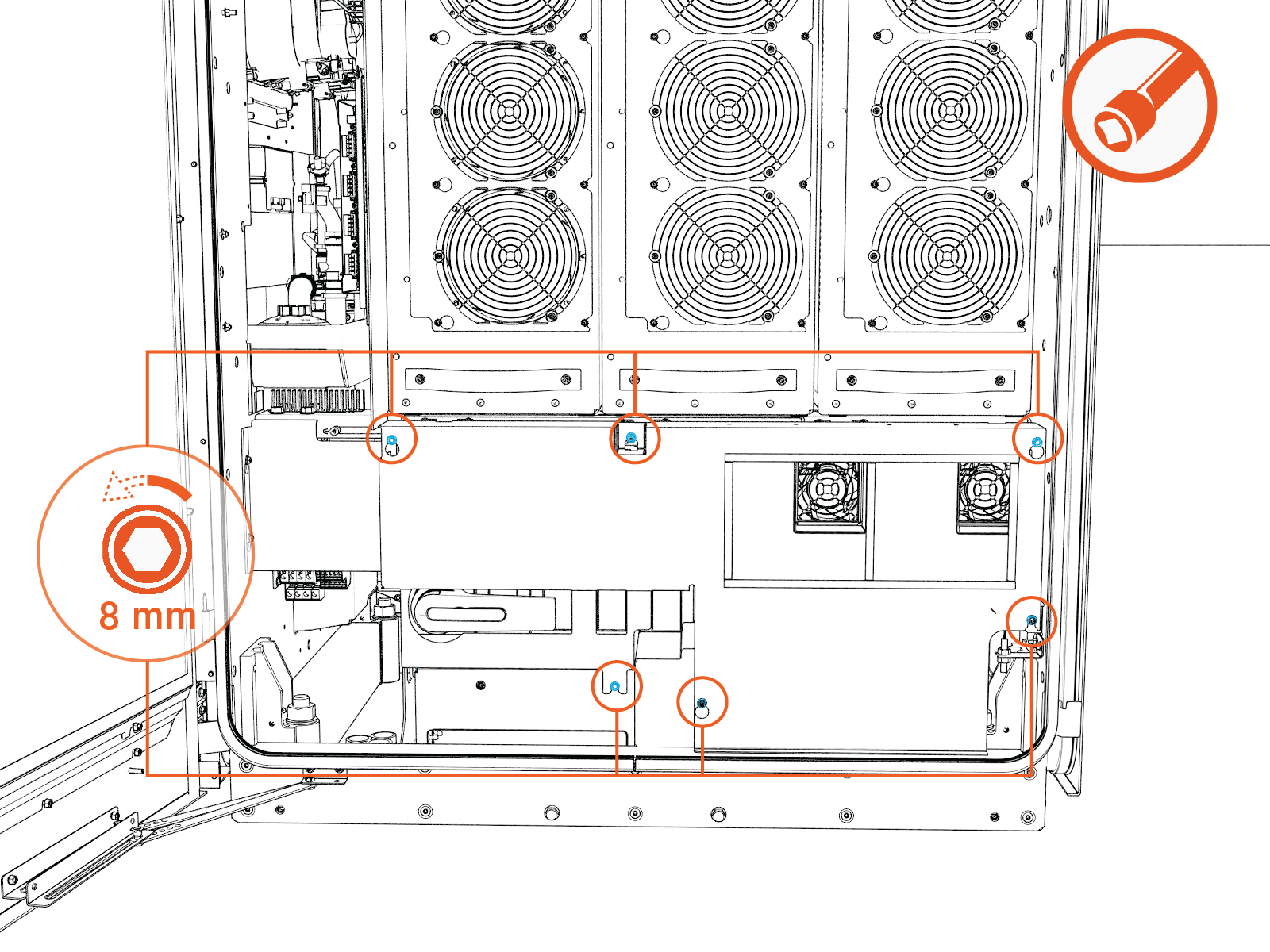
On the intake (right) side of the cabinet, loosen (do not remove) the nuts (x6) that secure the DC bus bars safety cover. Use a socket extender as needed.
-
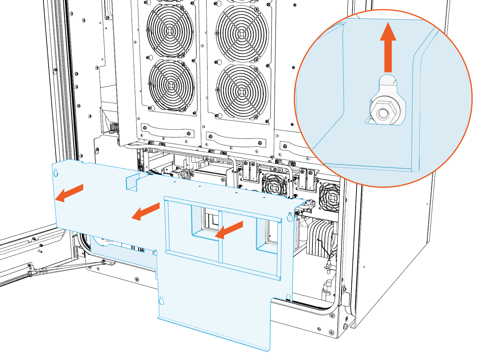
Slide the cover upward to release the keyholes. Then pull outward to remove the safety cover.
-
On the exhaust (left) side of the cabinet, loosen (do not remove) the nuts (x5) that secure the DC bus bar safety cover.
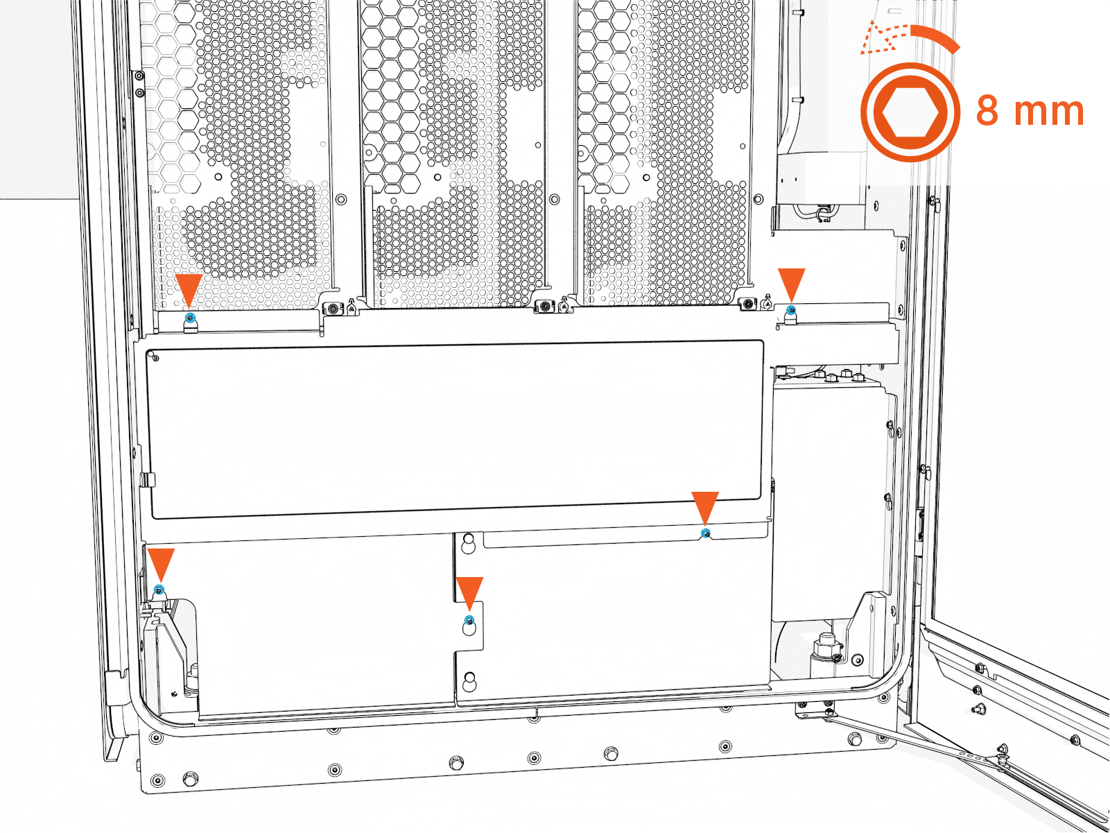
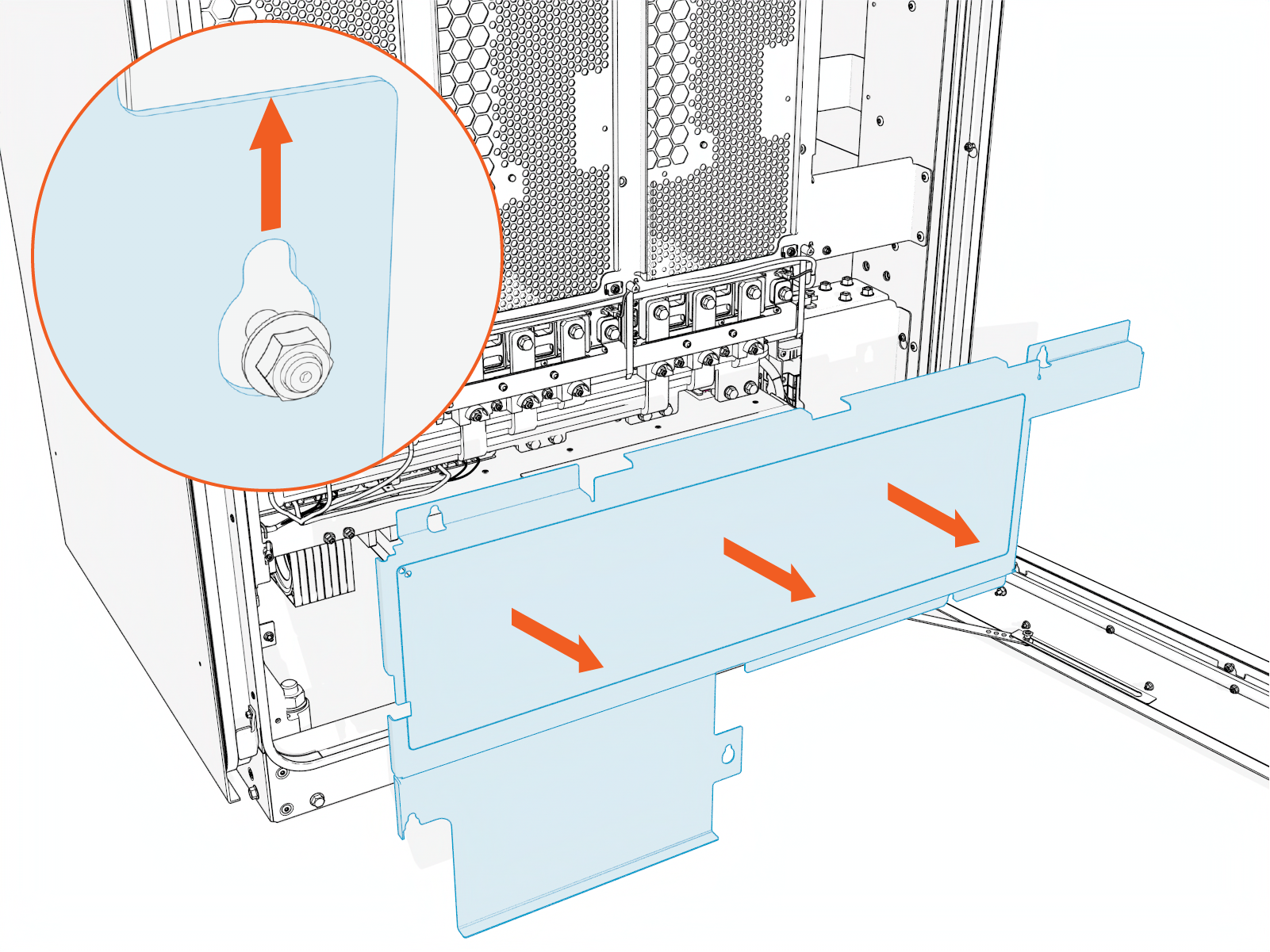
-
Slide the cover upward to release the keyholes. Then pull outward to remove the safety cover.
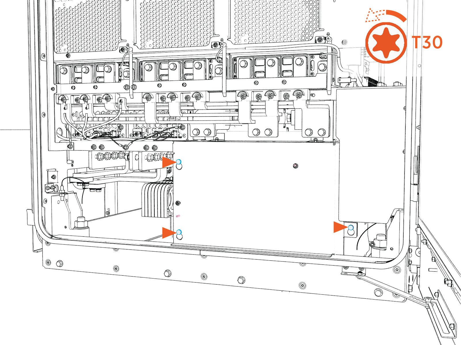
-
On the exhaust (left) side of the cabinet, loosen (do not remove) the nuts (x3) that secure the AC bus bars safety cover.
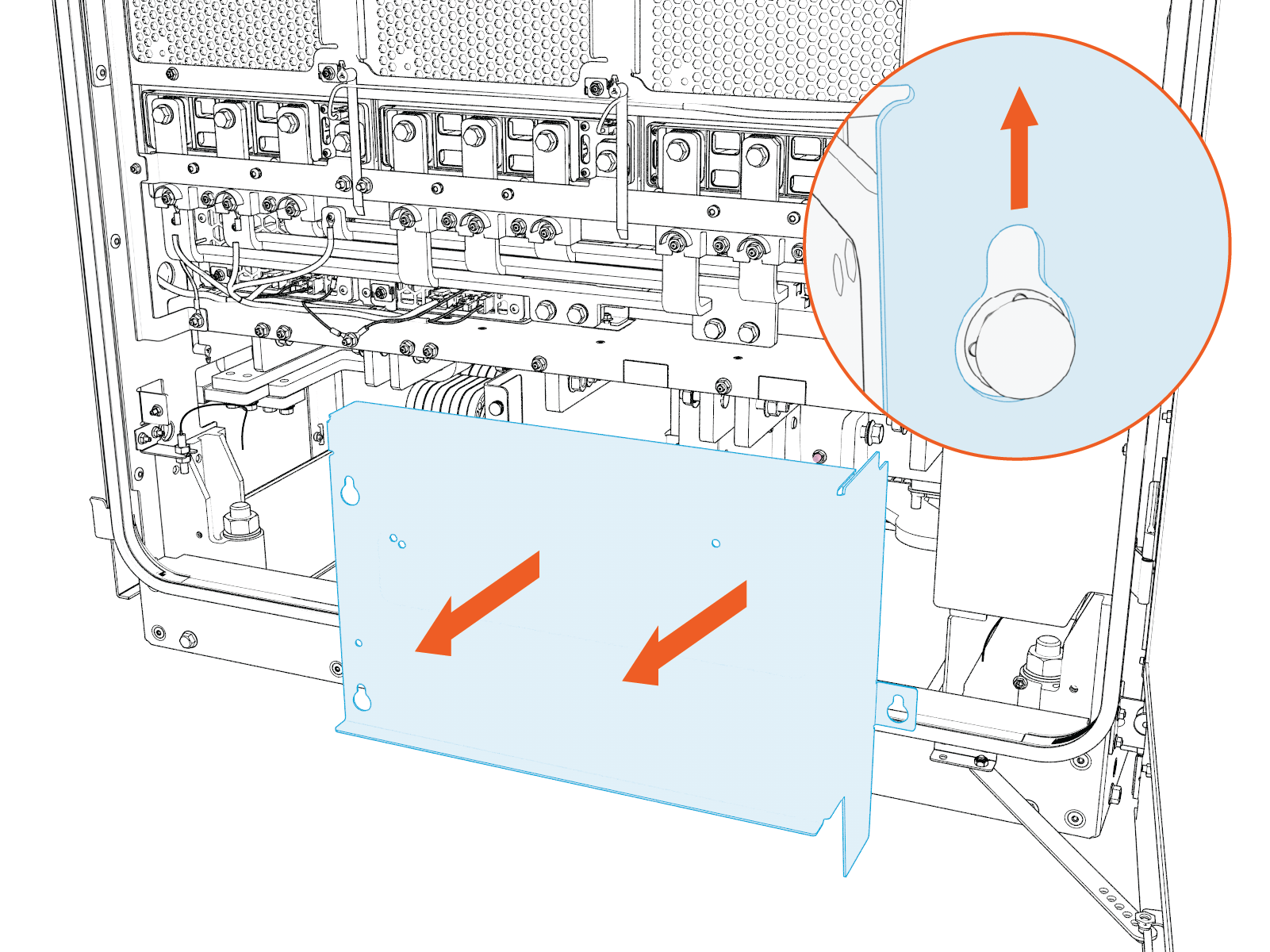
-
Slide the cover upward to release the keyholes. Then pull outward to remove the safety cover.
-
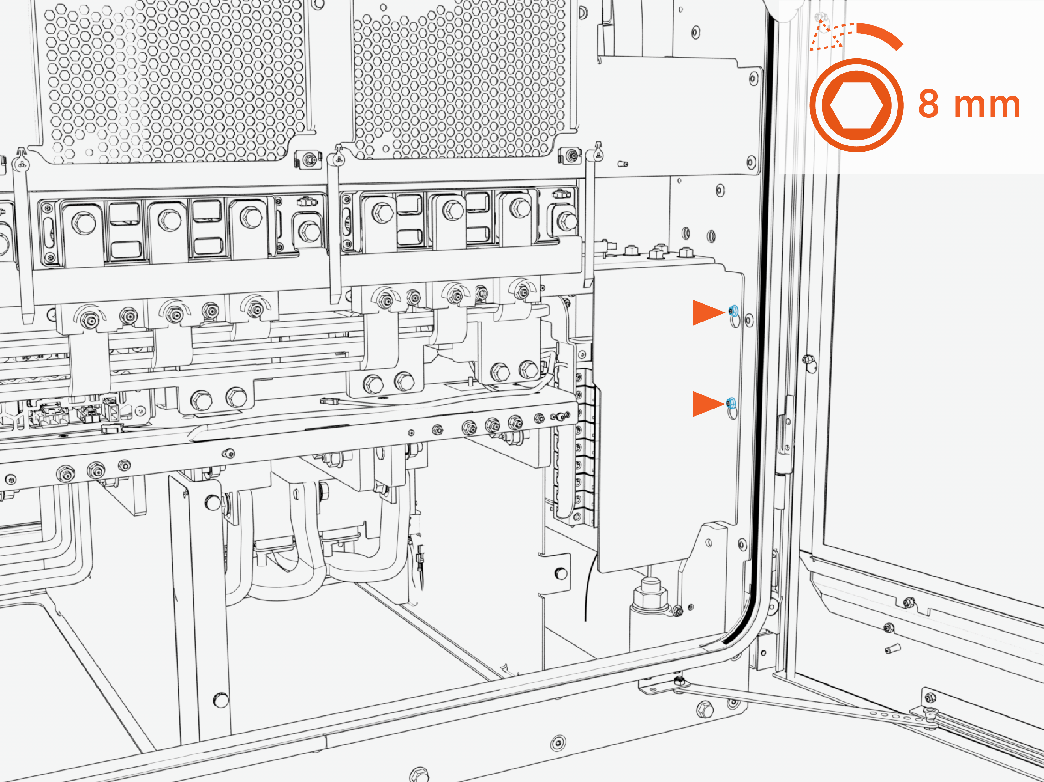
On the exhaust (left) side of the cabinet, loosen (do not remove) the nuts (x2) that secure the fuse block safety cover.
-
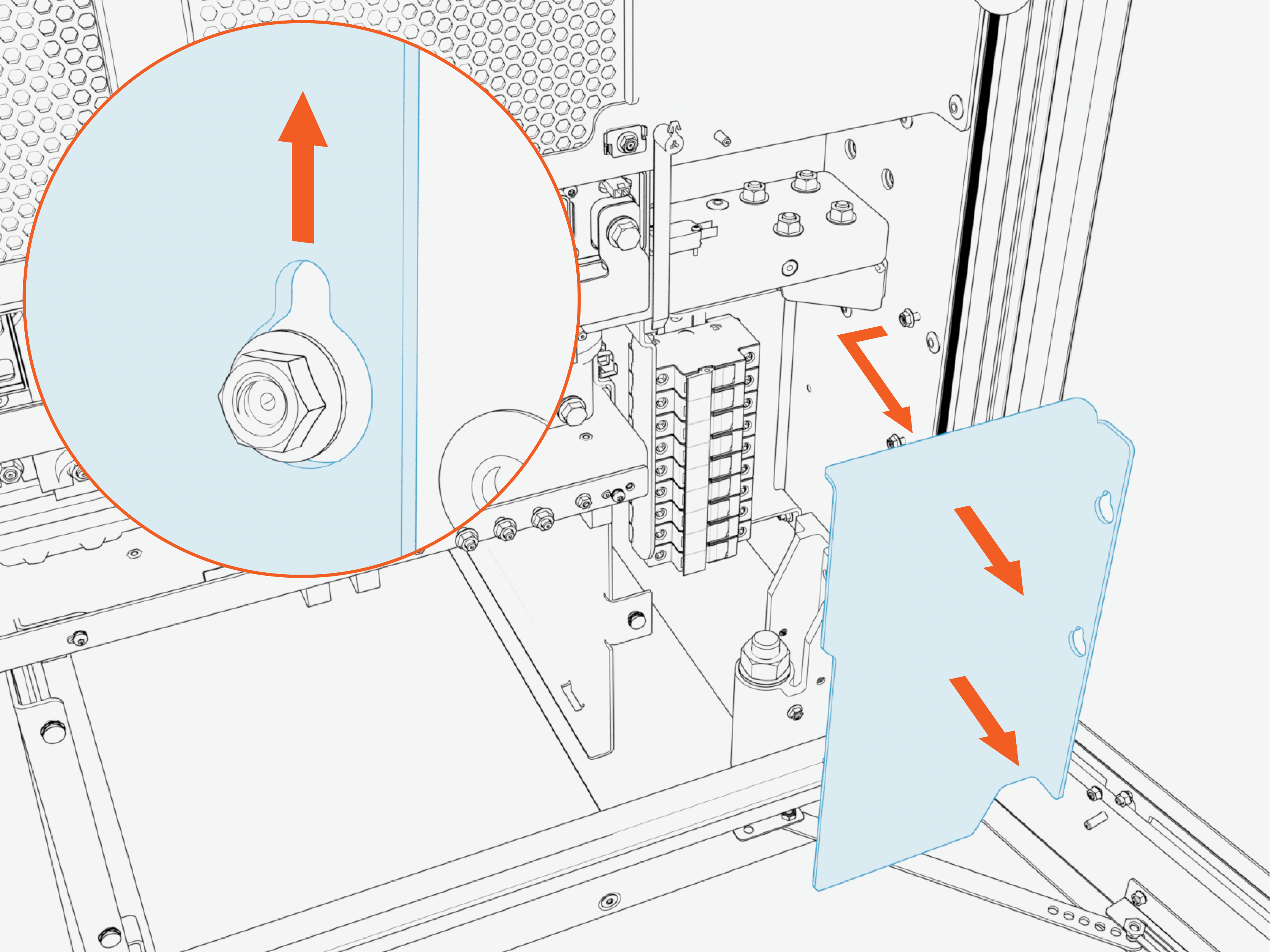
Slide the cover up to release the keyholes. Then pull outward to remove the safety cover.
-
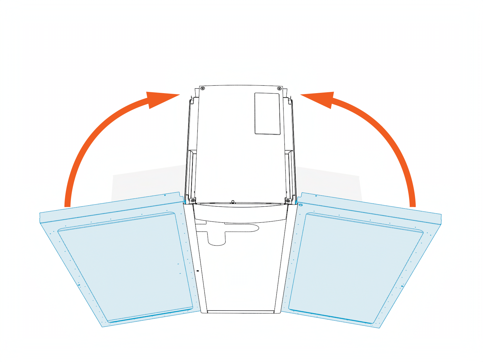
Disengage the door stays and close (do not lock) the intake and exhaust doors.
Lift Assembly
To install Power Block 2000, the assembly must be lifted from the shipping pallet. There two methods for lifting Power Block 2000:
-
Standard Eye Bolt Lift: Lift the Power Block 2000 assembly using eye bolts installed at the top of the assembly. This is the most common lift method.
-
Forklift Bracket Lift: If installing Power Block 2000 at a site with low clearance, the assembly may be lifted using forklift brackets installed at the sides of the assembly.
Follow instructions here to lift Power Block 2000 using the standard method. If installing at a low-clearance site, see Appendix: Low Clearance Forklift Bracket Lift.
-
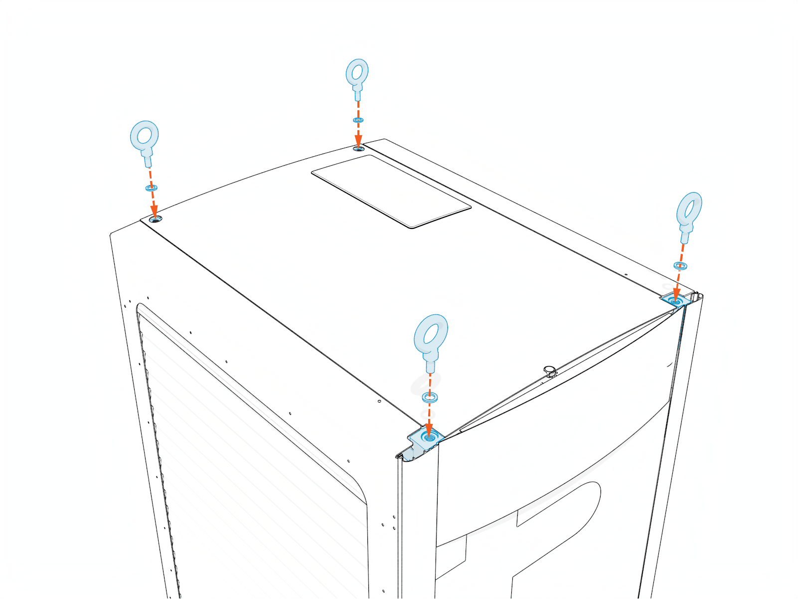
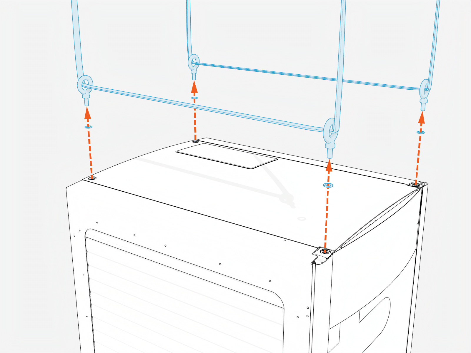
Install eye bolts with rubber washers (x4 each). Torque to 2 Nm (18 in-lb) minimum.
-
Thread lifting straps (x2) through eye bolts and install strap loops to hoisting equipment. Keep the straps slightly slack. Install a clamp on the end of the forklift tines to ensure lifting straps do not slip off tines.
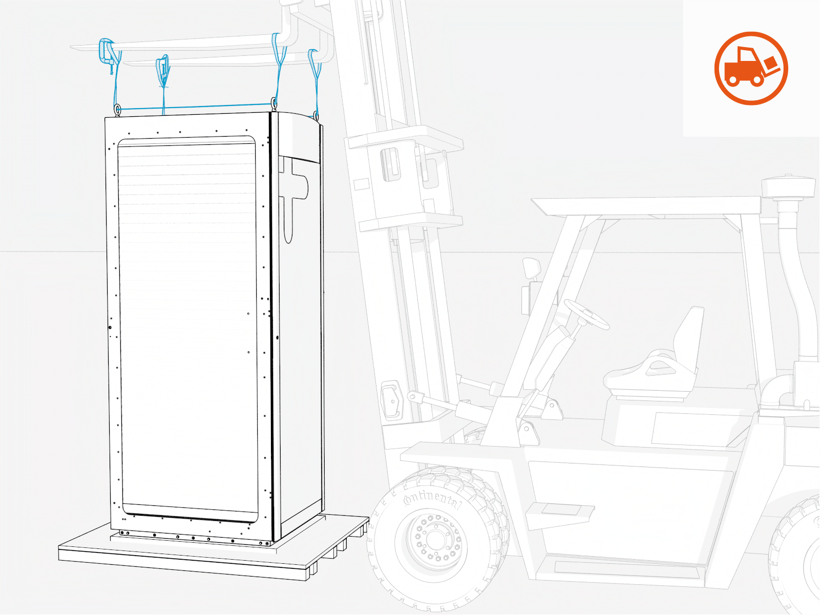
-
Open the intake door and locate two pallet bolts, one at each corner of the enclosure. Remove washer and nut from each pallet bolt.
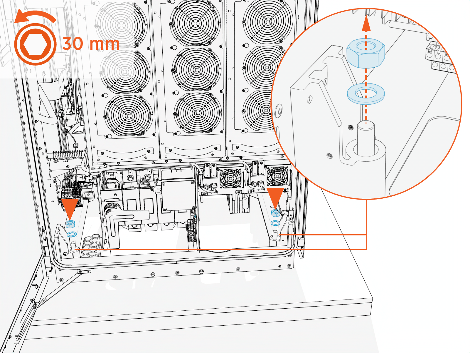
-
Open the exhaust door and locate two pallet bolts, one at each corner of the enclosure. Remove washer and nut from each pallet bolt.
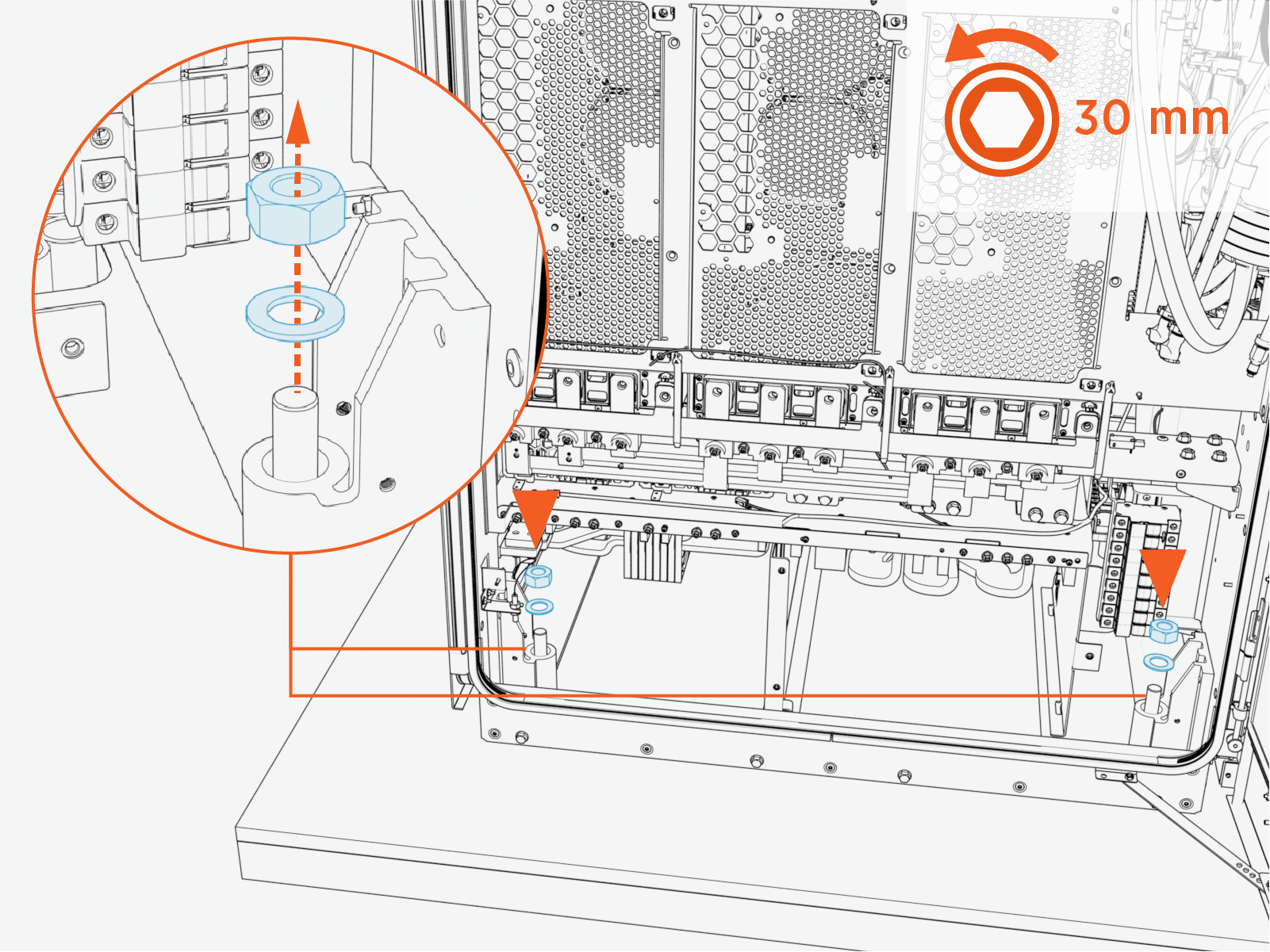
-
Close (but do not lock) the intake and exhaust doors and lift the assembly from the pallet.
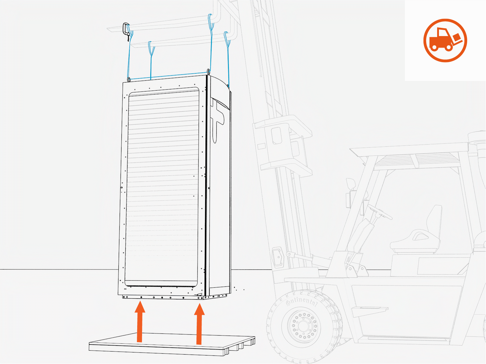
Mount Assembly
Follow steps below to mount the Power Block 2000 assembly. Illustrations depict the mounting procedure when using a forklift and lifting straps to mount the assembly. But the same concept at each step also applies when mounting the enclosure by forklift brackets.
-
Position the assembly over the anchor bolts and prepared cables.
Open the intake and exhaust doors when the assembly is near to the ground, to prepare for alignment of the assembly to the anchor bolts. Make sure the door stays are engaged, holding the doors open.
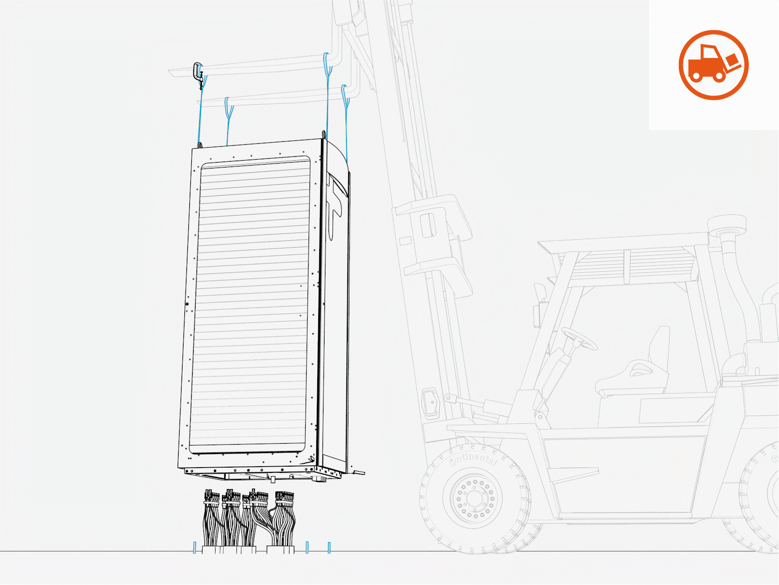
-
Carefully align and lower the assembly over the anchor bolts (x4) and completely onto the ground.
CAUTION: Make sure the AC input and external DC output cables are not disturbed as the assembly is lowered. The cables ends must align to the AC and DC bus bars within the assembly.WARNING: Risk of pinching or crushing of body parts. Keep all body parts clear when lowering the assembly to the ground.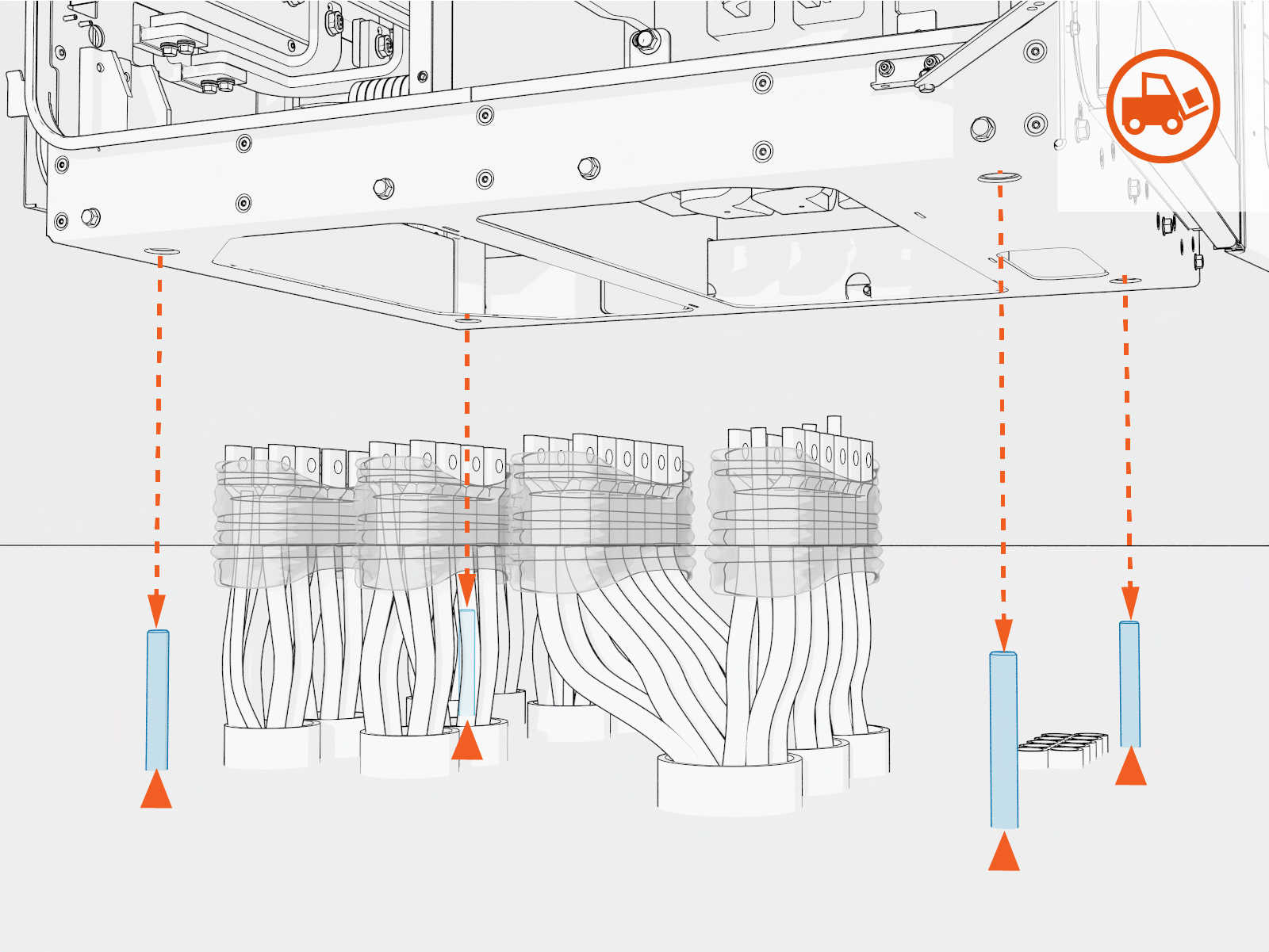
-
Check that the assembly is level and plumb.
-
On the intake side of the enclosure, install an M20 washer and nut onto each anchor bolt. Torque to 136 Nm (100 ft-lb).
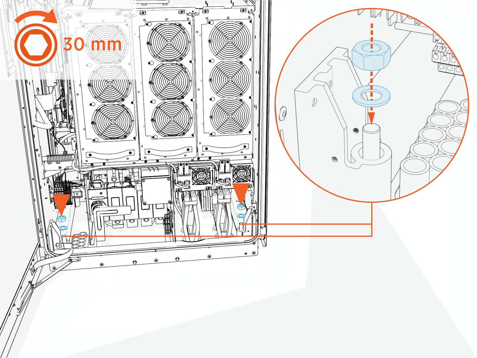
-
On the exhaust side of the enclosure, install an M20 washer and nut onto each anchor bolt. Torque to 136 Nm (100 ft-lb).
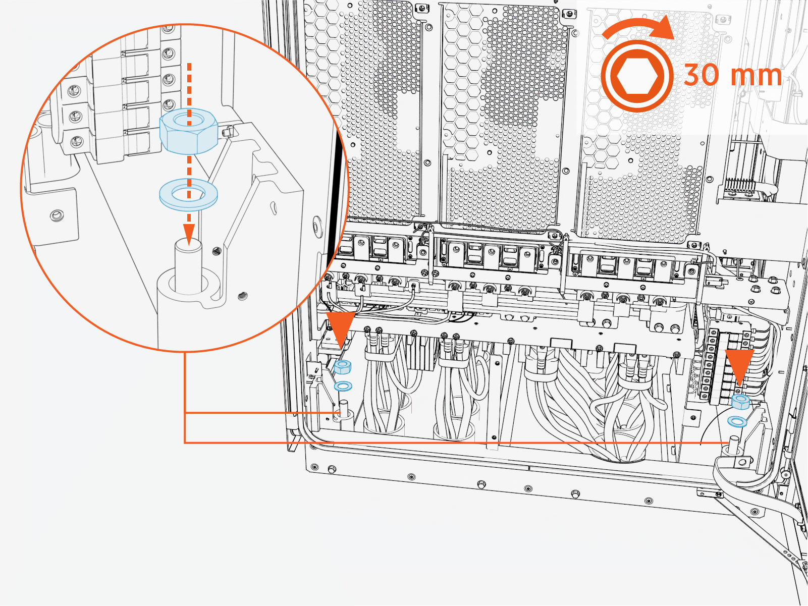
-
If the assembly was lifted using eye bolts, remove lifting straps, eye bolts, and eye bolt washers.
-
If the assembly was lifted using forklift brackets, remove the forklift brackets by reversing steps used to install the forklift brackets.
