Connect Wires
Follow all instructions provided in this section to connect wires.
This section contains images depicting wires and conduits. The size and quantity of conduits and wires shown are for illustrative purposes only. The actual quantity and size of conduits and wires for your specific site may vary and shall depend on site specific requirements.
Wire Terminal and Bus Bar Locations
Familiarize yourself with the wire terminal and bus bar locations illustrated below.
Intake Side
The following illustration identifies the wire ports, terminals, and bus bars accessible from the intake side (right side) of Express Solo. (Safety shields are hidden from view.) The AC input disconnect switch is also identified. Depending on the unit configuration, the AC disconnect switch may or may not be present.
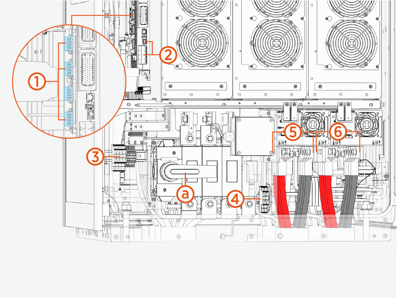
|
Ref |
Part |
|---|---|
| (1) |
Safety Hub ports |
| (2) |
Ethernet ports |
| (3) |
DC terminal block for 48 V DC, soft shutdown switch, door interlock sensor wires |
| (4) |
Shunt trip terminals |
| (5) |
DC BUS (intake side) bus bars |
| (6) |
EXT B bus bars |
| (a) |
AC input disconnect switch (presence of this switch depends on unit configuration) |
The DC wire terminal block allocations are given below:
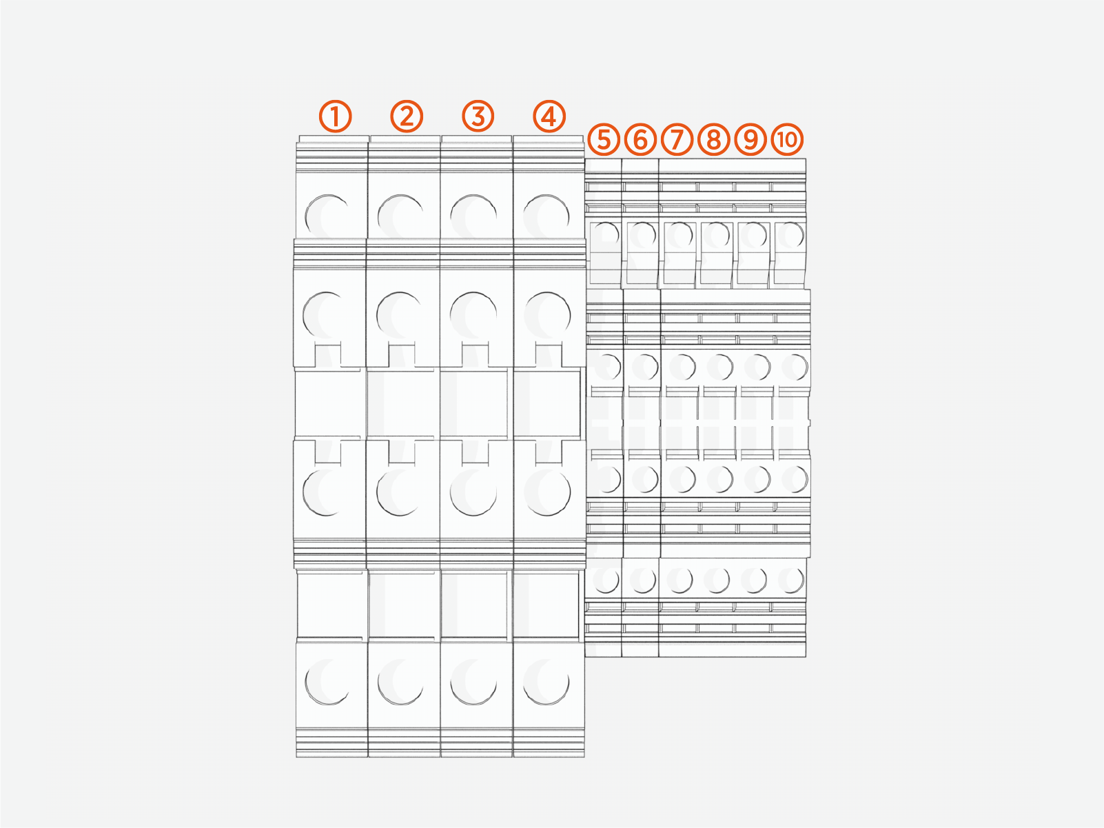
|
Ref |
Allocation |
|---|---|
| (1) |
48 V DC positive (+) to Power Link #1 |
| (2) |
48 V DC negative (-) to Power Link #1 |
| (3) |
48 V DC positive (+) to Power Link #2 |
| (4) |
48 V DC negative (-) to Power Link #2 |
| (5) |
Soft shutdown switch |
| (6) |
Door interlock sensor |
| (7) |
Not used for Express Solo |
| (8) |
Not used for Express Solo |
| (9) |
Not used for Express Solo |
| (10) |
Not used for Express Solo |
The shunt trip terminal allocations are given below:
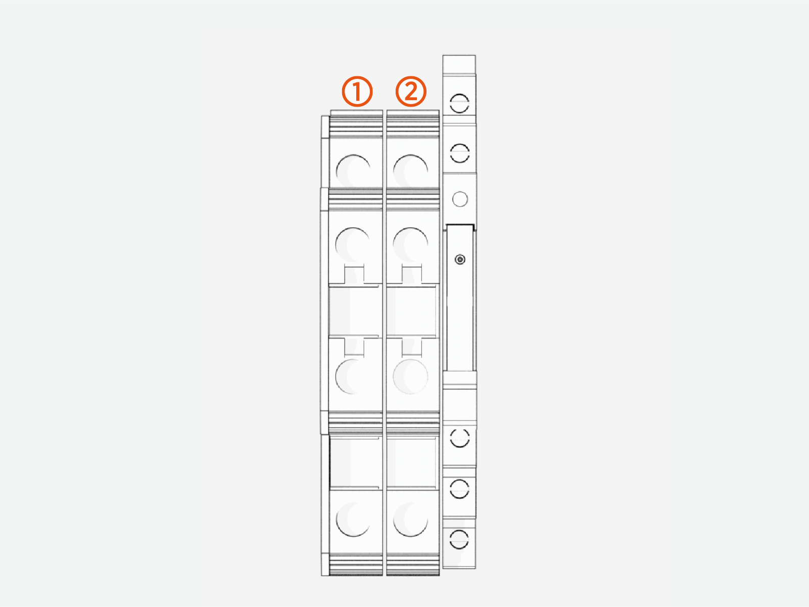
|
Ref |
Allocation |
|---|---|
| (1) |
Shunt 1 |
| (2) |
Shunt 2 |
Exhaust side
The following identifies the wire terminals and bus bars accessible from the exhaust side (left side) of Express Solo. (Safety shields are hidden from view.)
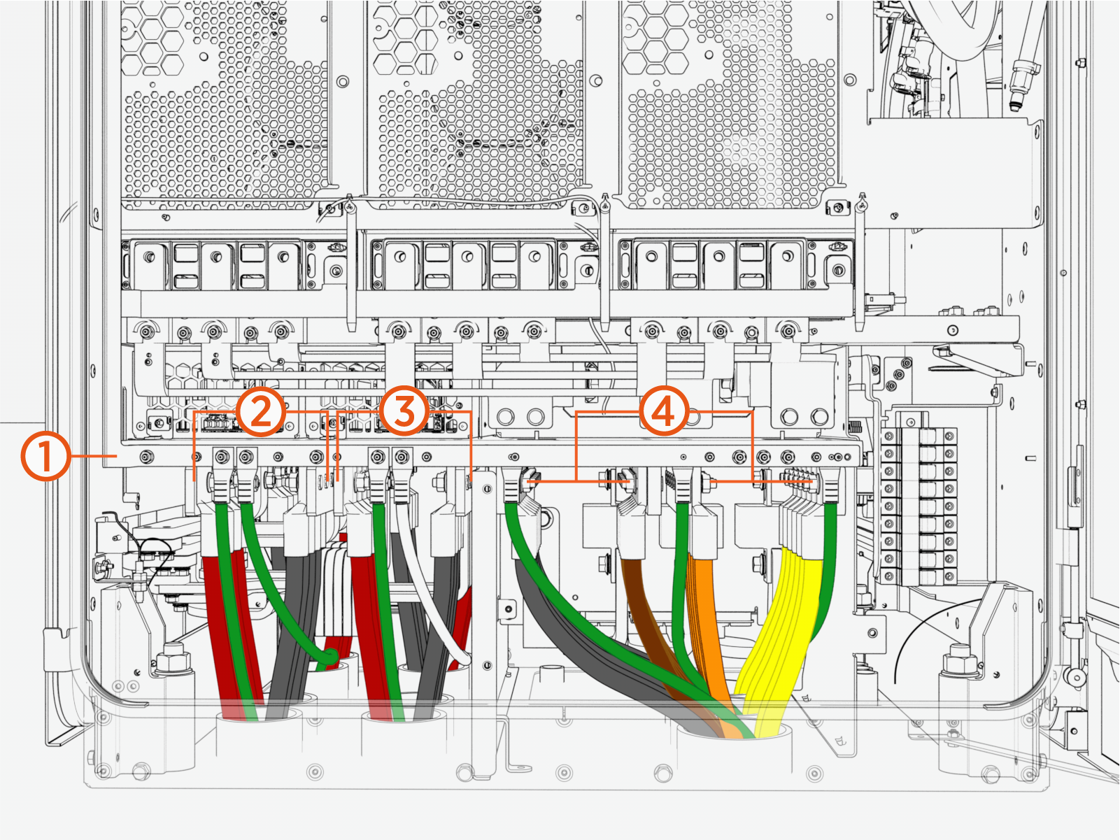
|
Ref |
Part |
|---|---|
| (1) |
Ground/PE bar (with wire landing studs) |
| (2) |
EXT D bus bars |
| (3) |
DC BUS (exhaust side) bus bars |
| (4) |
AC input (L1, L2, L3) and neutral bus bars |
Unwrap Wires
Carefully remove cling film from the wires.
Use caution if using a sharp tool to cut the cling film. Do not damage the wires when removing the cling film.
Connect AC Input Wires
Follow steps below to connect the AC input wires.
-
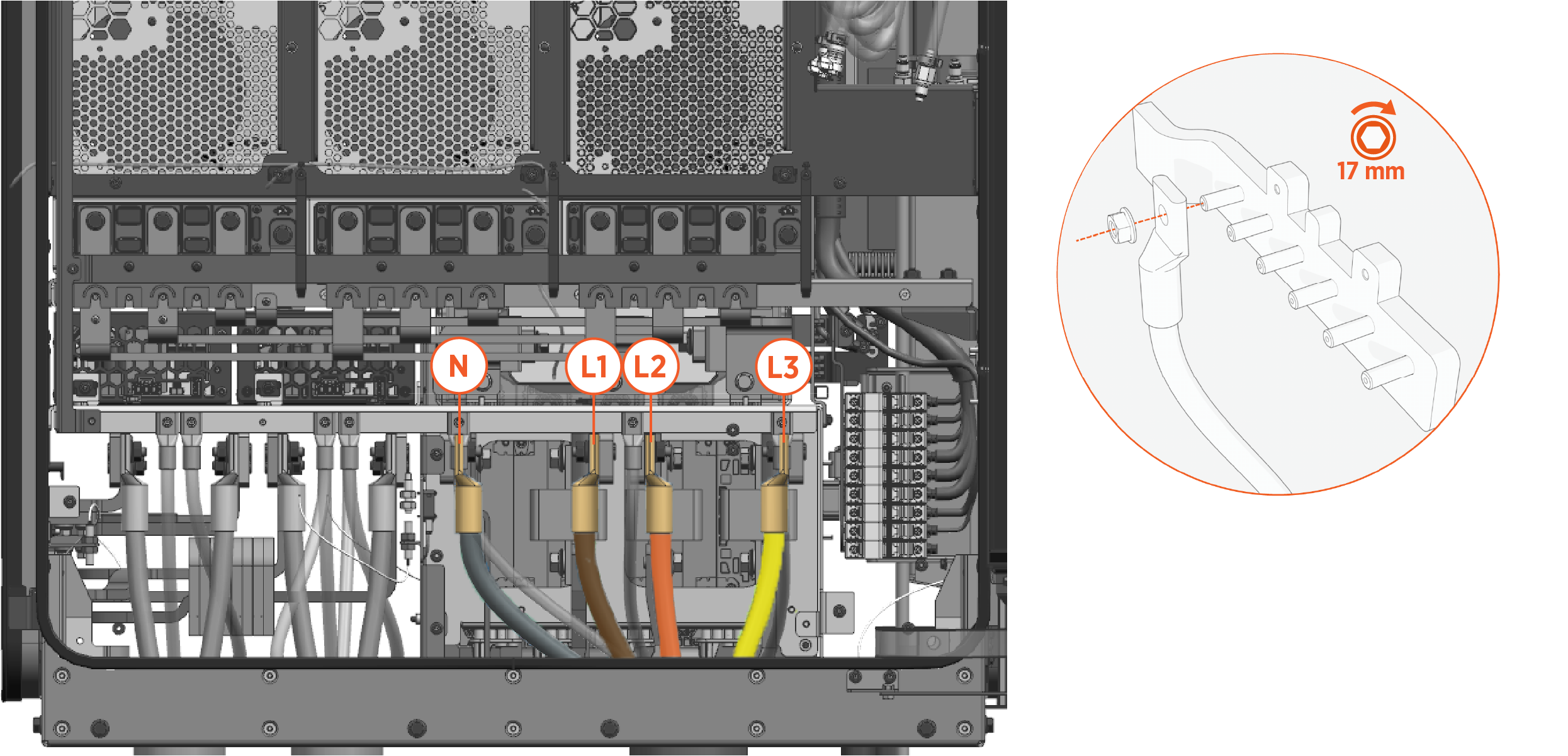
Use the wire landings diagram to locate the AC input wire bus bars. The bus bars are accessible on the exhaust side (left side) of Express Solo.
-
Install each AC input wire onto a wire landing stud with provided M10 nut. If recommended by the wire manufacturer or local code, apply dielectric grease to the back of the lug. Start at the inner-most landing and work your way out. Torque nut to 19 Nm (14 ft-lb).
-
Apply torque marks to all torqued connections.
Connect AC Protective Earth (PE) Wires
Follow steps below to connect the AC input PE wires.
-
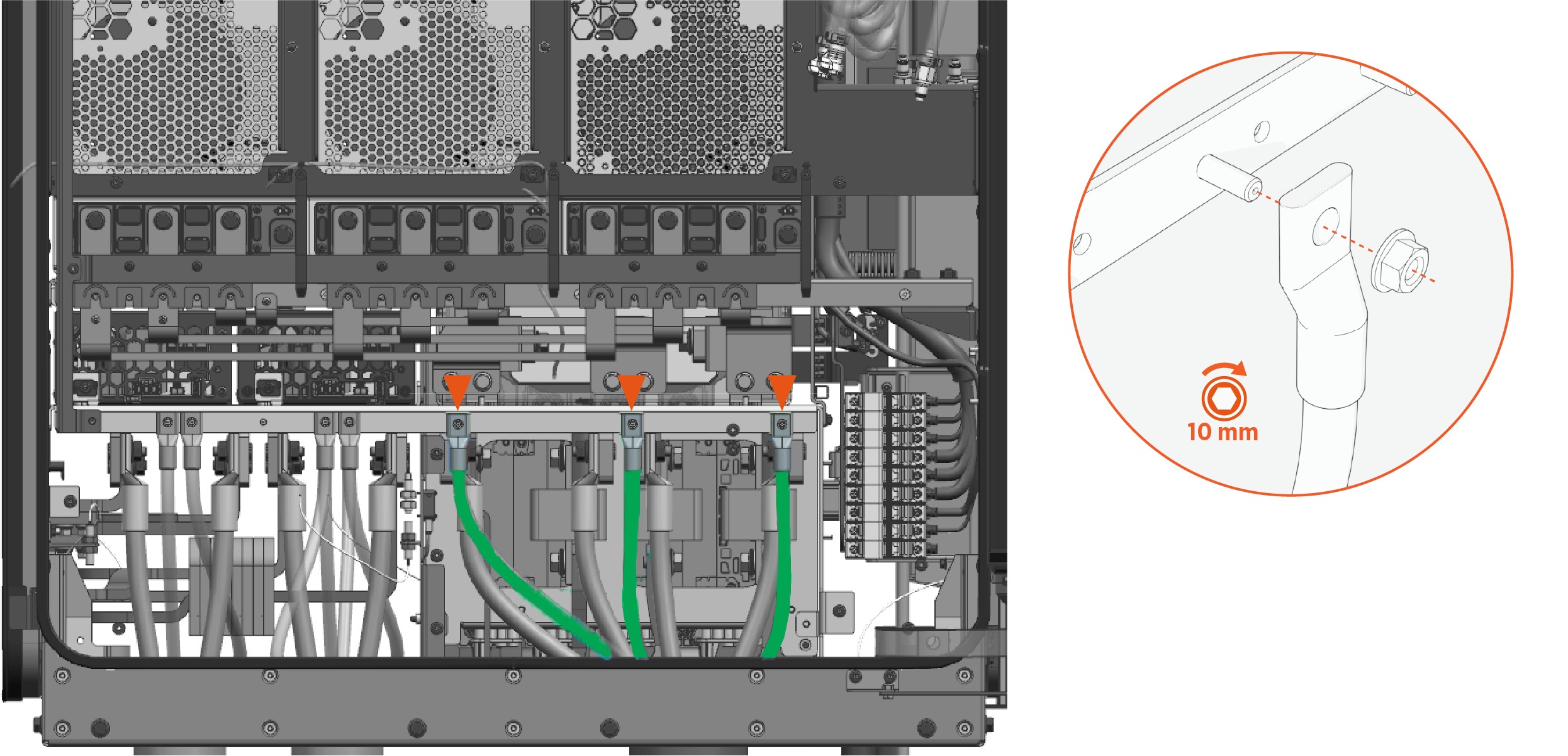
Use the wire landings diagram to locate the PE landing studs. The studs are accessible on the exhaust side (left side) of Express Solo.
-
Temporarily install the AC input PE wire lugs onto the ground bar using provided M6 nuts. Use a 10 mm socket to hand-tighten.
-
Measure and cut the PE wires to length.
-
Remove the lugs from the ground bar.
-
Terminate each PE wire with a lug:
-
Mark the lug's barrel height on the cable.
-
Strip the wire jacket. Use a suitable wire stripper, such as a Klein tool.
-
If recommended by the wire manufacturer or local code, apply an anti-oxidant joint compound to the bare cable to make a gastight joint with the lug.
-
Insert the stripped wire end into the lug barrel and crimp it. Use a suitable lug crimping tool and/or die recommended by the lug manufacturer.
-
-
Install each PE wire onto a wire landing stud with provided M6 nut. Torque nut to 5.6 Nm (50 in-lb).
Connect DC BUS Wires
Follow steps below to connect the DC BUS wires.
-
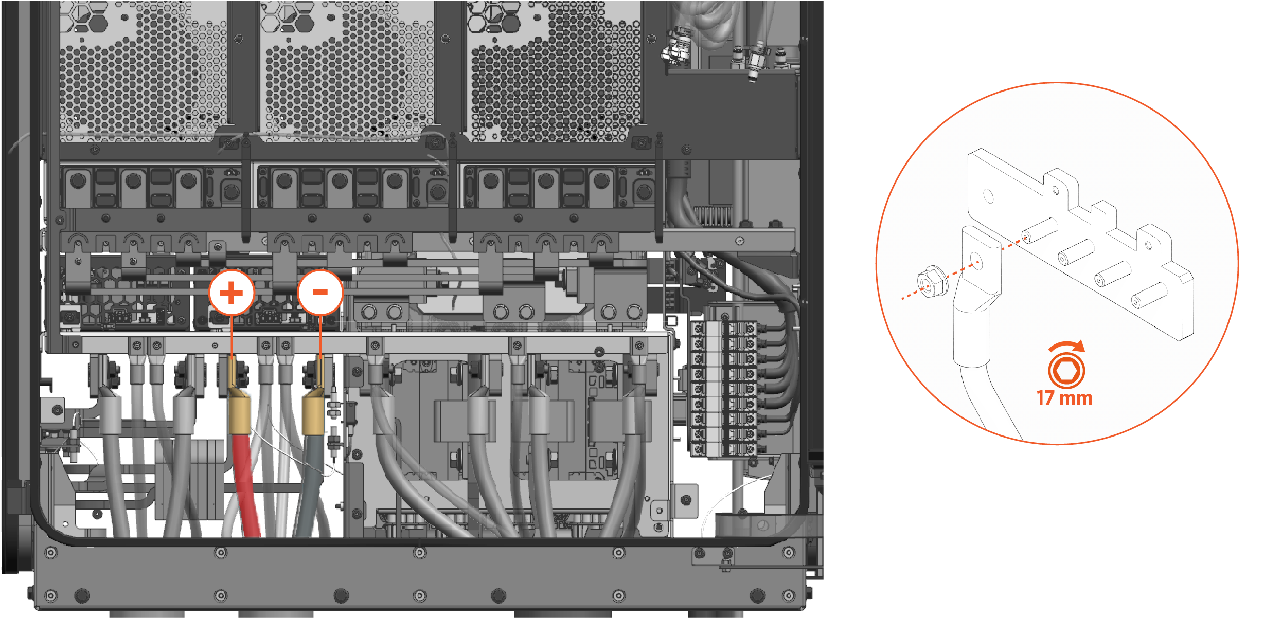
Use the wire landings diagram to locate the DC BUS wire bus bars. The bus bars are accessible on both the intake side (right side) and exhaust side (left side) of Express Solo.
-
Install each DC BUS wire onto a wire landing stud with provided M10 nut. If recommended by the wire manufacturer or local code, apply delectric grease to the back of the lug. Start at the inner-most landing and work your way out. Torque nut to 19 Nm (14 ft-lb).
The illustration below depicts DC BUS wire installation on the exhaust side.
-
Apply torque marks to all torqued connections.
Connect External DC Output Wires
Follow steps below to connect the external DC output (EXT B and EXT D) wires.
-
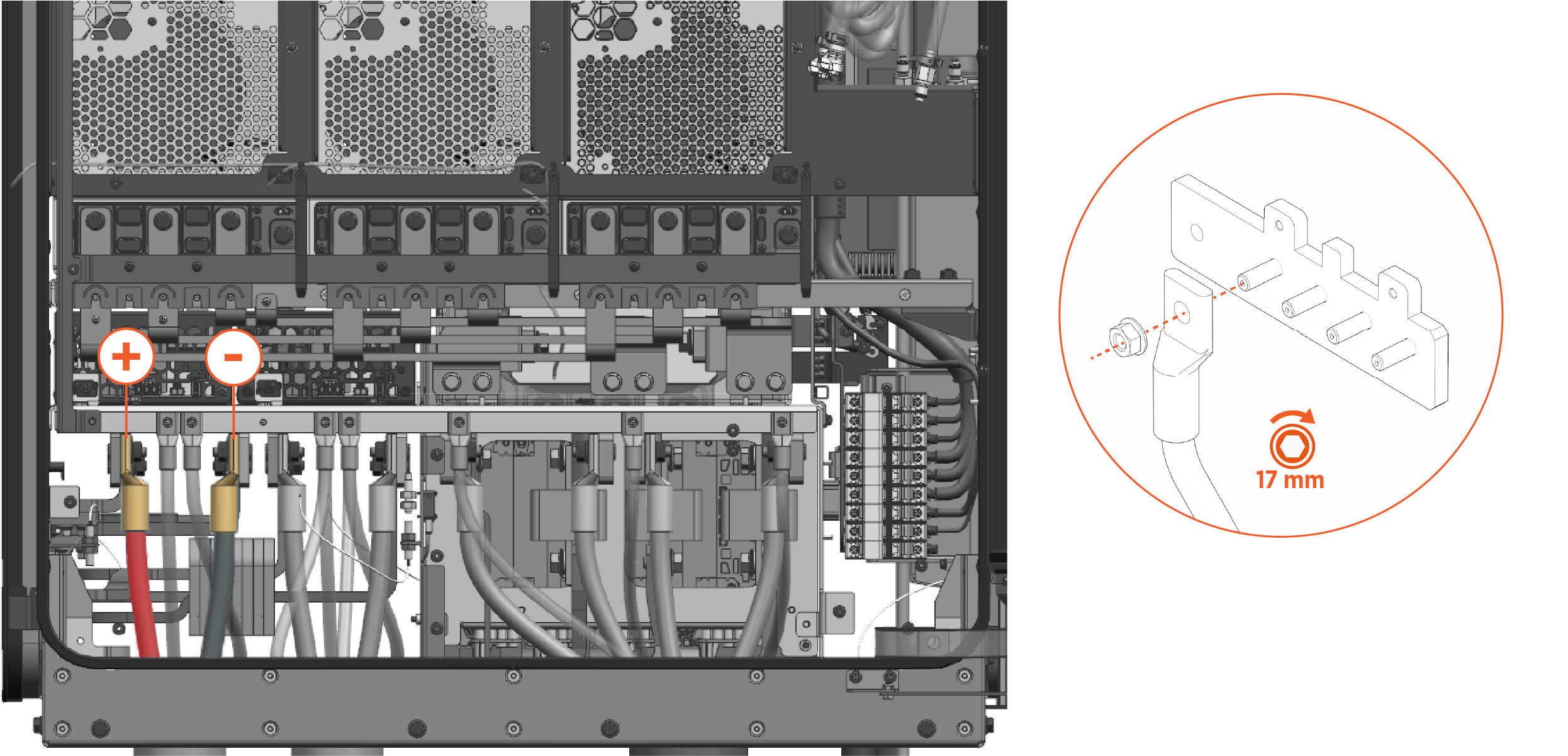
Use the wire landings diagram to locate the EXT B and EXT D wire bus bars. The bus bars are accessible on both the intake side (right side) and exhaust side (left side) of Express Solo.
-
Install each DC wire onto a wire landing stud with provided M10 nut. If recommended by the wire manufacturer or local code, apply delectric grease to the back of the lug. Start at the inner-most landing and work your way out. Torque nut to 19 Nm (14 ft-lb).
The illustration below depicts EXT D wire installation on the exhaust side.
-
Apply torque marks to all torqued connections.
Connect External DC Output and DC BUS Grounding Wires
In this guide, "ground" refers to Protective Earth (PE).
Follow steps below to connect the external DC output and DC BUS grounding wires.
-
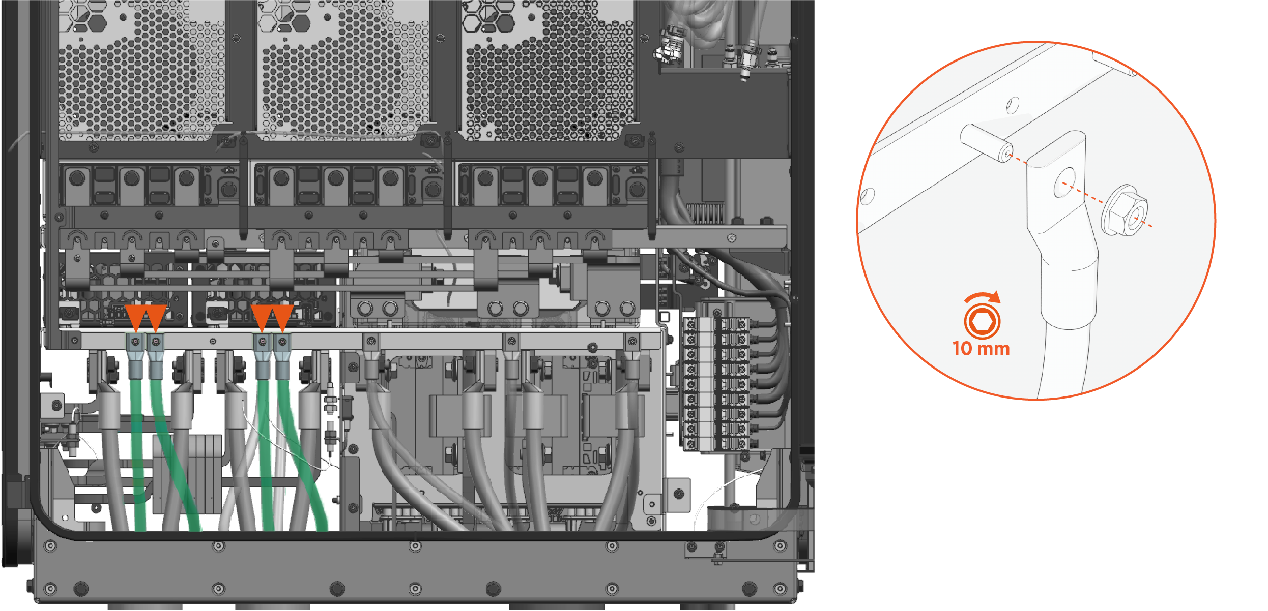
Use the wire landings diagram to locate wire landing studs on the ground bar. The bar is accessible on the exhaust side (left side) of Express Solo.
-
Using same method used to install the AC input PE wires, install each grounding wire onto a wire landing stud with provided M6 nut. Torque nut to 5.6 Nm (50 in-lb).
Pull Remaining Wires
Pull remaining wires into the Express Solo enclosure. Depending on the site-specific system architecture, this may include one or more of the following:
-
48 V DC wires
-
Ethernet cables
-
Door interlock sensor wires
-
Safety Hub wires
-
Soft shutdown switch wires
-
Shunt trip wires
To pull the wires:
-
Study the line diagram carefully to understand which wires should be pulled through each conduit.
-
Label all wires at both ends.
-
Pull the wires through conduit.
Connect 48 V DC Wires
-
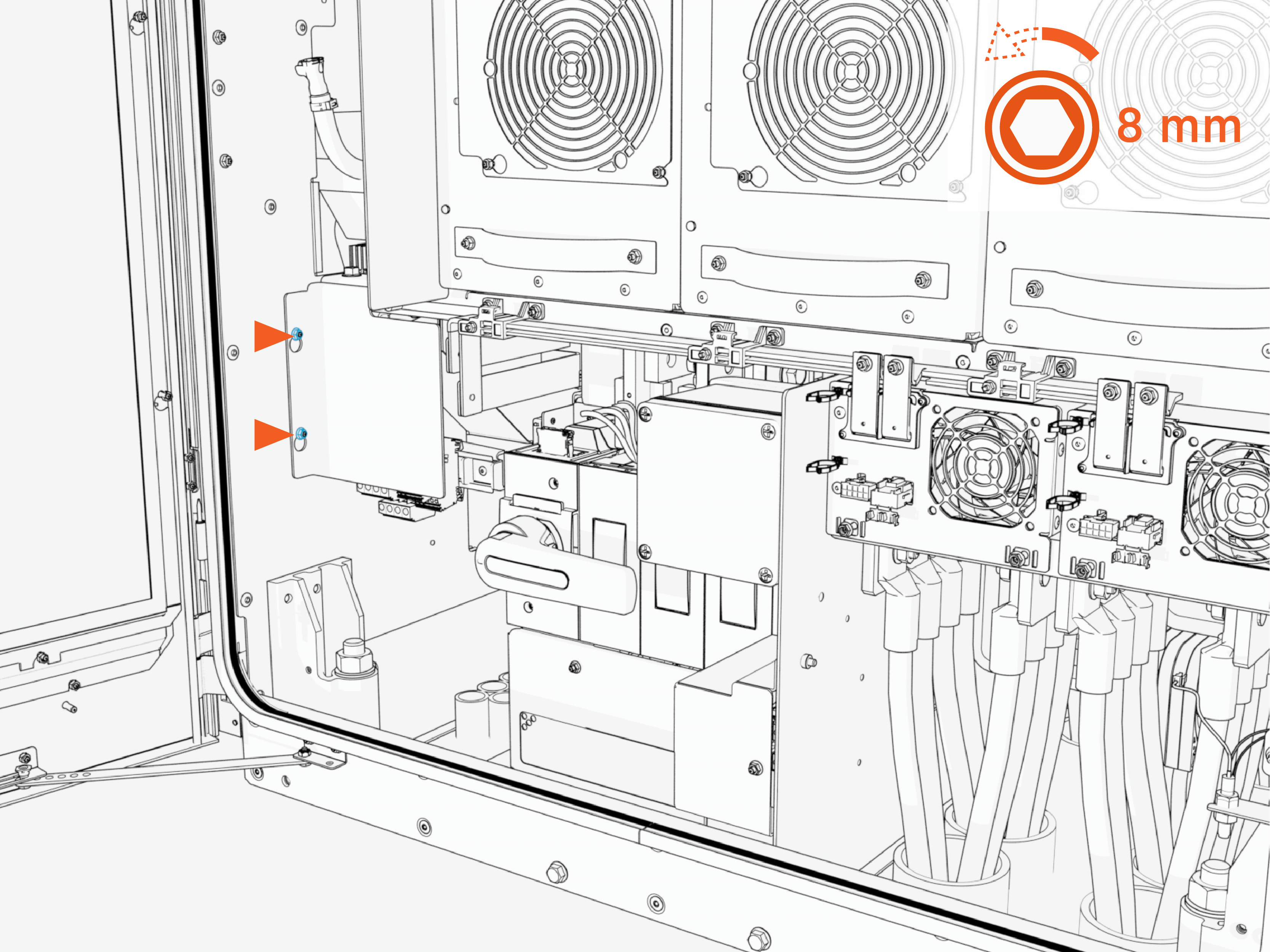
On the intake (right) side of the cabinet, loosen (do not remove) nuts (x2) that secure the DC terminals cover.
-
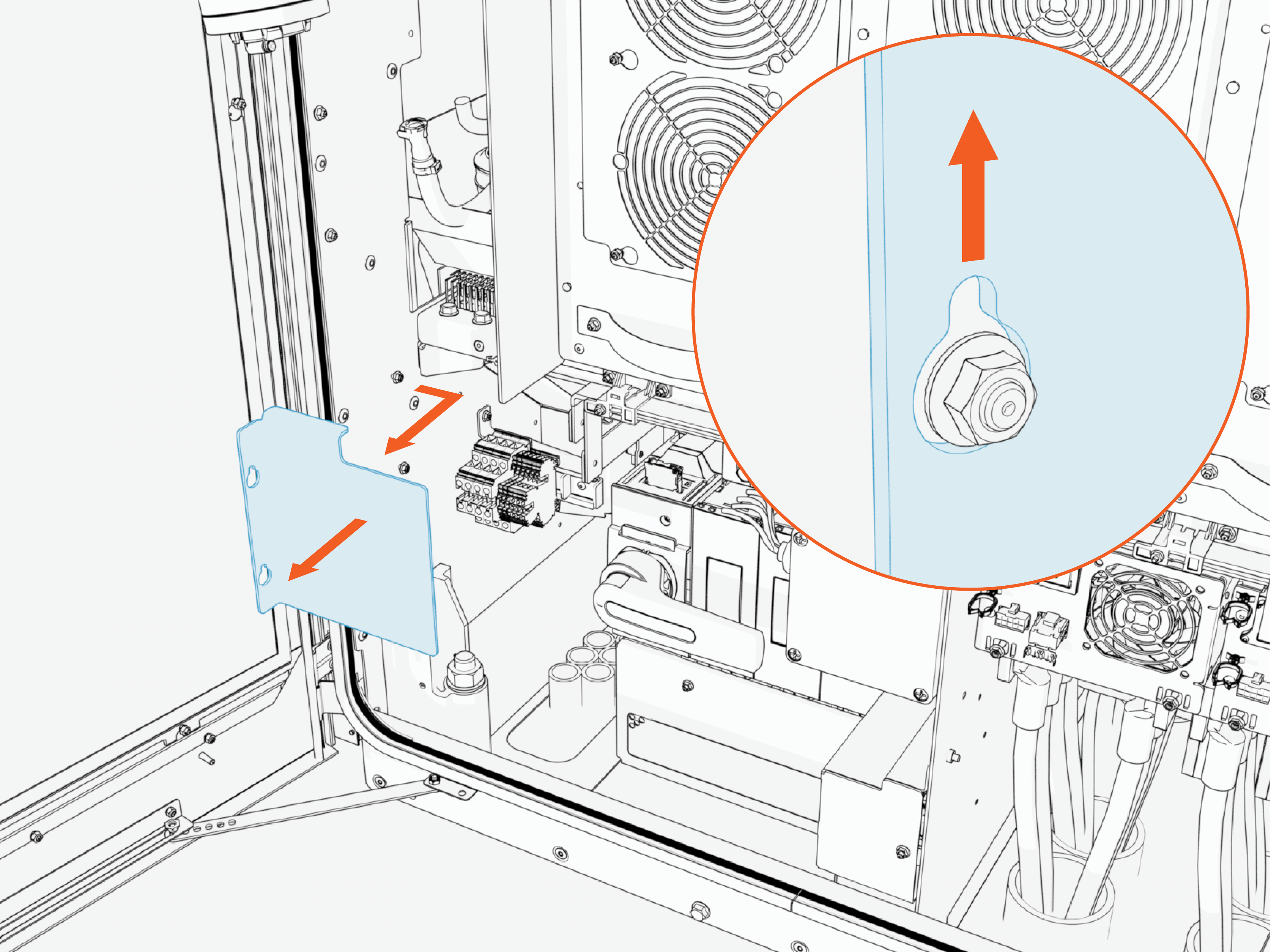
Slide the cover up to release the keyholes. Then pull outward to remove the safety cover.
-
Use the wire landings diagram to locate the 48 V DC terminals within the cabinet. The terminals are accessible on the intake side (right side) of Express Solo.
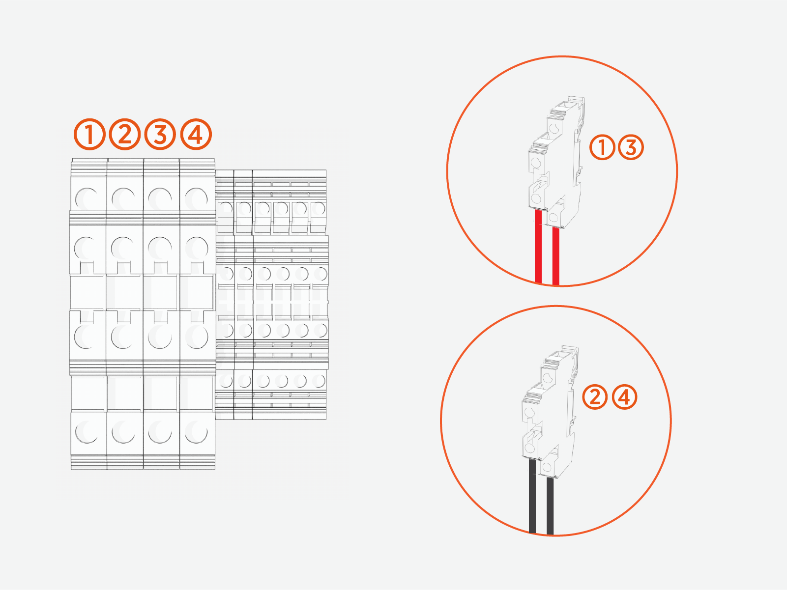
(1) Positive (+) 48 V DC to Power Link #1
(2) Negative (-) 48 V DC to Power Link #1
(3) Positive (+) 48 V DC to Power Link #2
(4) Negative (-) 48 V DC to Power Link #2
Each 2-level terminal is equipped with:
- Upper-level wire insertion point with corresponding set screw
- Lower-level wire insertion point with corresponding set screw
Within a single terminal, the two levels are interchangeable.
-
Route the 48 V DC wires through the wireway clamps up to the 48 V DC terminals. If necessary use cable ties to secure the wires.
-
Install the wires at each terminal with the following steps:
-
Cut the wire (or wires) to length for landing at the terminal.
-
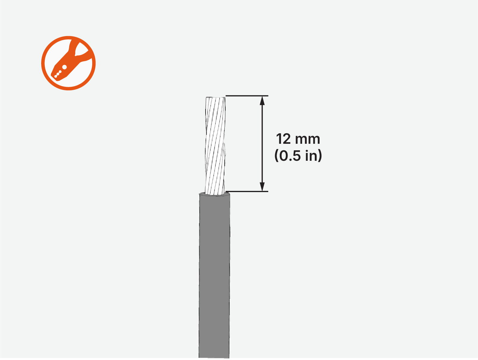
Strip the wire jacket. If using a wire ferrule, install the ferrule after stripping the conductor.
-
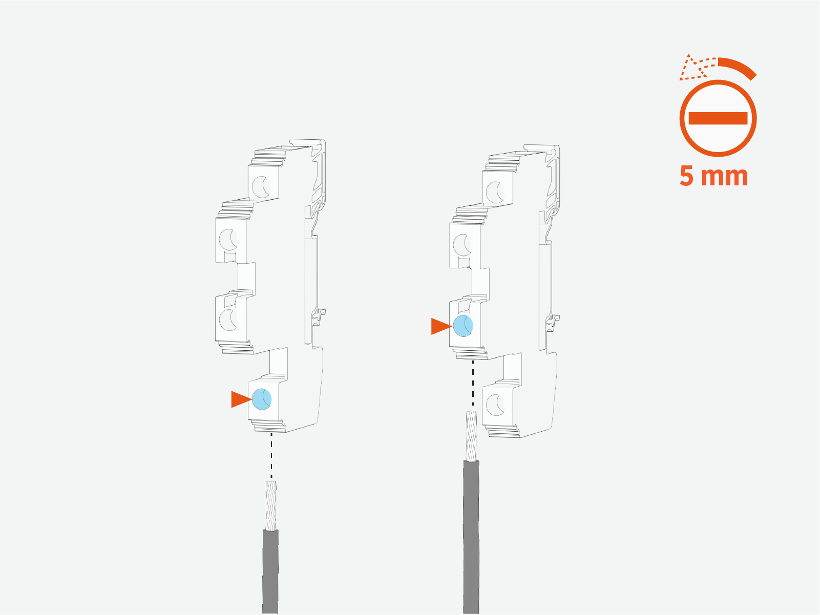
On the terminal, loosen the set screw for each level where a wire will be inserted.
-
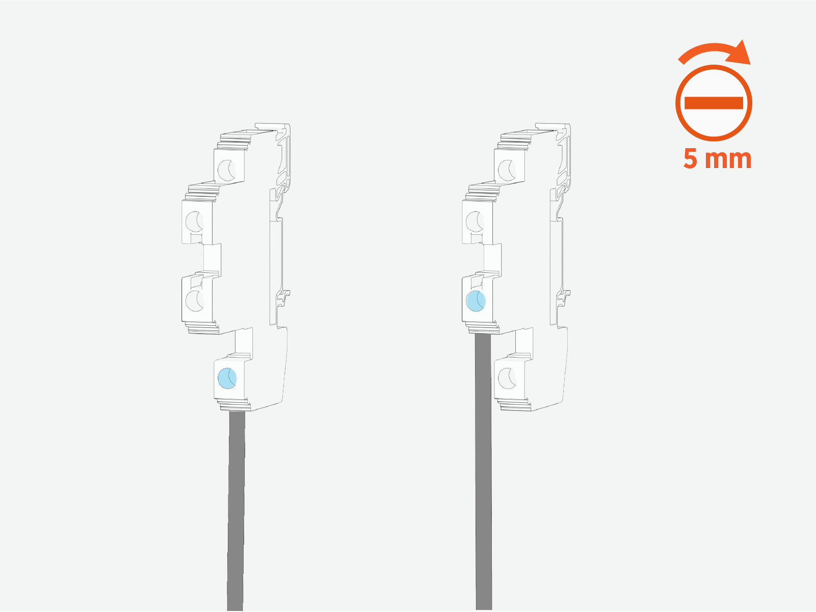
Insert the wire (or wires) into the terminal. Torque the set screws (x2) to 2 Nm (18 in-lb).
-
Push-pull to test that all wires (+ and -) are firmly secured.
-
Connect Ethernet Cables
Follow steps below to connect the Ethernet cables.
-
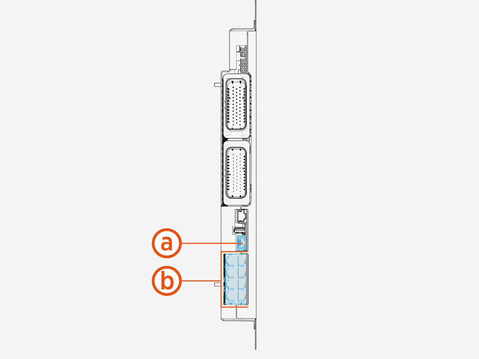
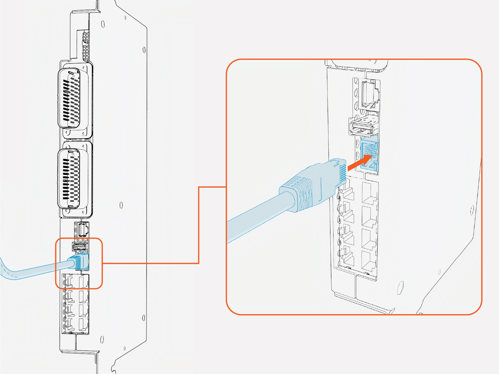
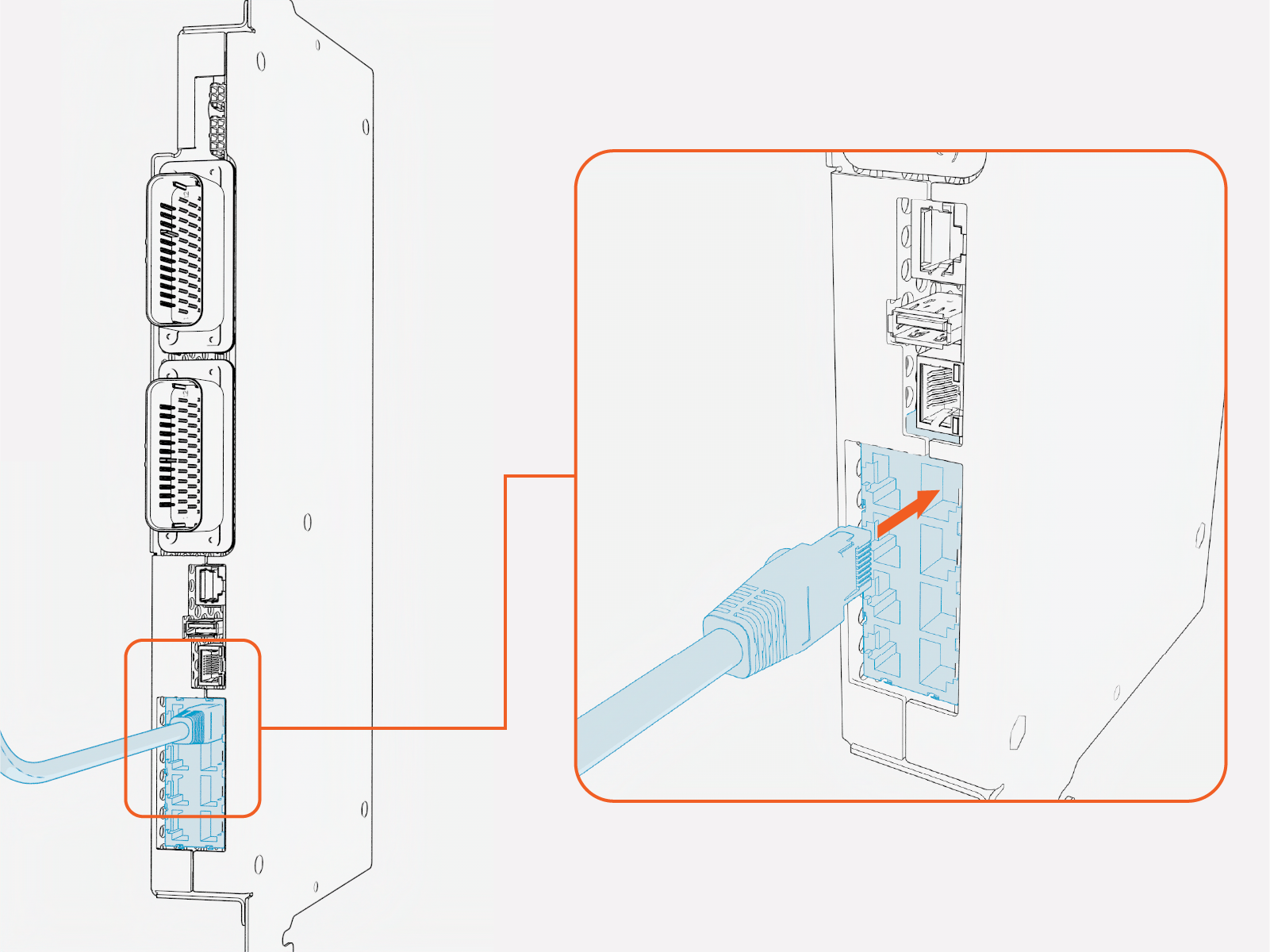
Use the wire landings diagram to locate and identify the Ethernet ports on the Power Management Controller (PMC) within the cabinet. The PMC is accessible from the intake side (right side) of Express Solo.
-
Hardwire Ethernet port.
-
Ethernet ports for connection to Power Link or another Express Solo. There are eight ports and all ports are equivalent.
-
Route the Ethernet cables through the wireway clamps up to the PMC.
-
Install each Ethernet cable with the following steps:
-
Trim Ethernet (Cat6 STP
 Shielded Twisted Pair) cable to length, allowing for a service loop.
 -
Field crimp a shielded RJ45 connector onto the Ethernet cable. Use straight-through T568B pattern.
-
If the Ethernet cable connects from the Express Solo to a Power Link, ground the cable shield at the Express Solo end (and not at the Power Link end)
.
-
If the Ethernet cable connects between two Express Solos, ground the cable shield at only one Express Solo. That Express Solo is designated as the main unit within the cluster.

-
-
Test the Ethernet cable for functionality.
If using a Paige OSP Shielded GameChanger cable for a wire run length greater than 100 m (328 ft), follow the test procedure specified by Paige. See Paige GameChanger Resources.

-
Insert the Ethernet cable into the appropriate Ethernet port. To establish a secure connection, the RJ45 connector latch must click into the switch.
Inserting hardwire Ethernet cable:
Inserting Ethernet cable that connects to a Power Link or another Express Solo:
-
Connect Door Interlock Sensor and Soft Shutdown Switch Wires
Follow steps below to connect the door interlock sensor and soft shutdown switch wires, as needed.
-
Use the wire landings diagram to locate the door interlock sensor terminal and soft shutdown switch terminals within the cabinet. The terminals are accessible on the intake side (right side) of Express Solo. The procedure for installing wires at each terminal is the same.
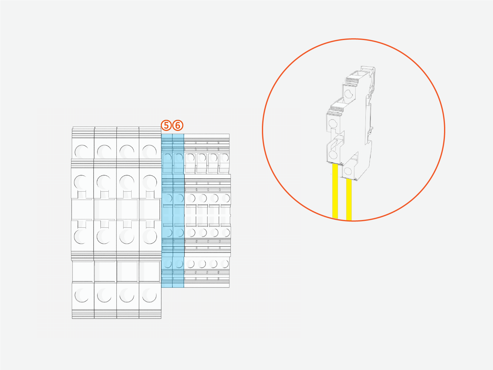
(5) Soft shutdown switch terminal
(6) Door interlock sensor terminal
Each 2-level terminal has:
- Upper-level wire insertion point with corresponding set screw
- Lower-level wire insertion point with corresponding set screw
The soft shutdown switch wires are non-polarized and interchangeable. Either wire can be installed into either level on the soft shutdown switch terminal.
The door interlock sensor wires are non-polarized and interchangeable. Either wire can be installed into either level on the door interlock sensor terminal.
Do not confuse the soft shutdown switch terminal (5) with the door interlock sensor terminal (6). These terminals are not interchangeable.
-
Follow procedures below to connect a wire pair at its designated terminal:
-
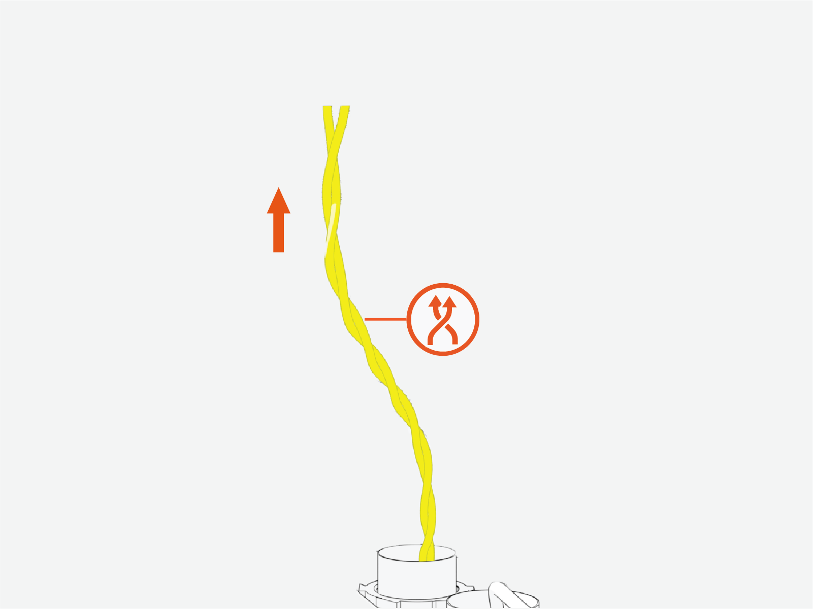
Twist the wires together, using a minimum of five twists per foot.
-
Route the twisted wire pair through the wireway clamps up to the terminal. If necessary use cable ties.
-
Cut the wires to length for landing at the terminals.
-
Strip the wire jackets. If using wire ferrules, install the ferrules after stripping the conductors.
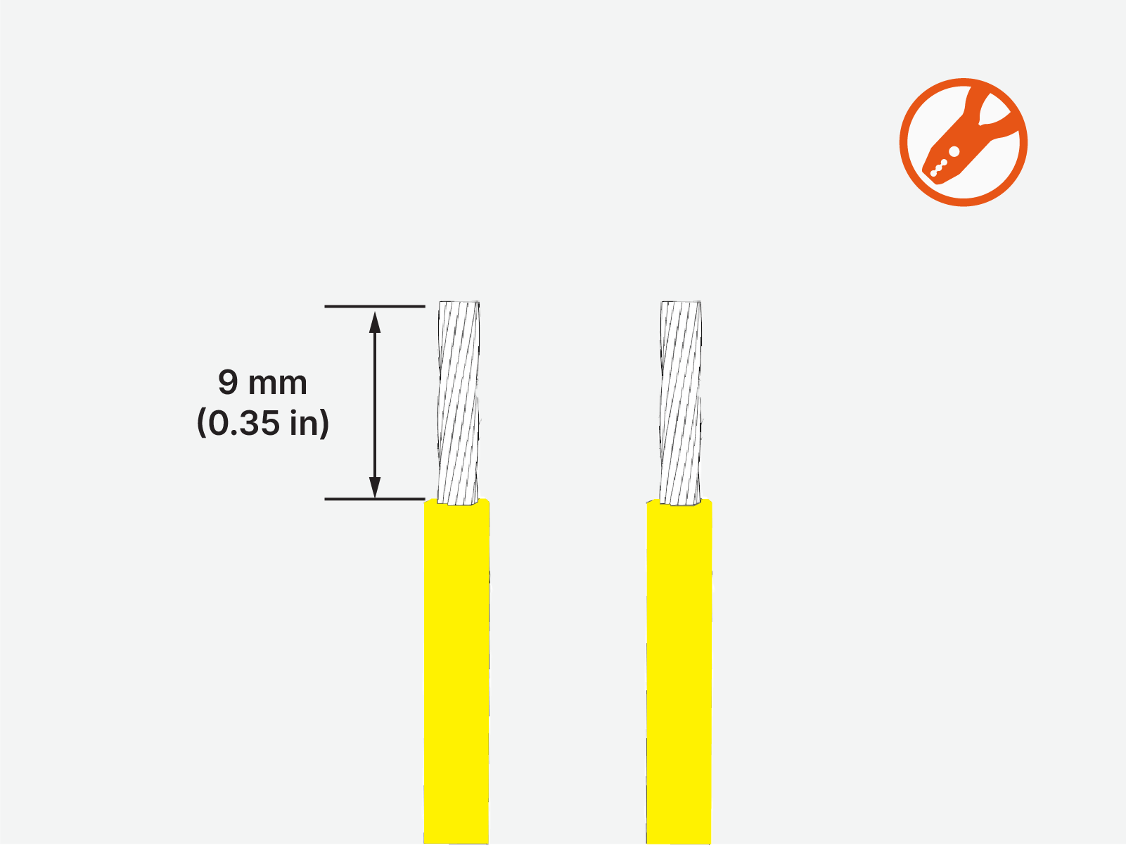
-
At the wire terminal, loosen the wire set screws (x2). Use a 3.5 mm flathead screwdriver.
-
Insert the wires into the terminal. Torque the set screws (x2) to 0.6 Nm (5.3 in-lb).
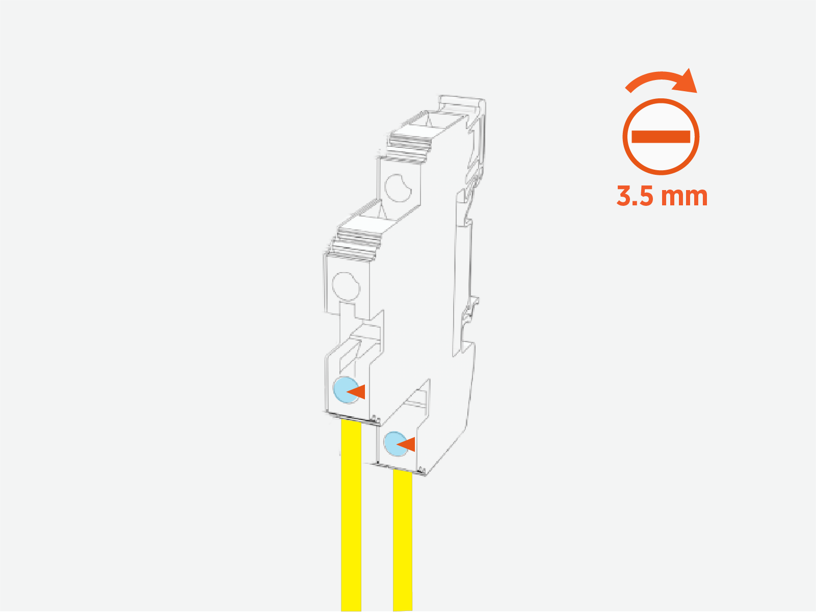
-
Push-pull to test that both wires (+ and -) are secured.
-
Connect Safety Hub Wires
Safety Hub wiring provides electrical‑isolation monitoring between the Express Solo and each connected Power Link.
Depending on the Power Link model used in the installation, the Safety Hub connection at the Express Solo will require either:
-
A twisted‑pair field‑wire connection, or
-
A jumper installed on the Safety Hub Board
Refer to the site design guide and installation guide of the Power Link model specific to your project to determine whether the Power Link requires a Safety Hub twisted-pair connection or a jumper installation. Then proceed through the applicable sections below to install the required wiring.
Identify Safety Hub Board Location, Terminals, and Pin Ports
Refer to Wire Terminal and Bus Bar Locations to locate the Safety Hub board within the Express Solo cabinet.
The Safety Hub Board is equipped with four terminals denoted A, B, C, and D. The terminal allocations are given below. Terminals B and D are equipped with a 5-pin terminal plug. The pin ports on each plug are numbered 1–5.
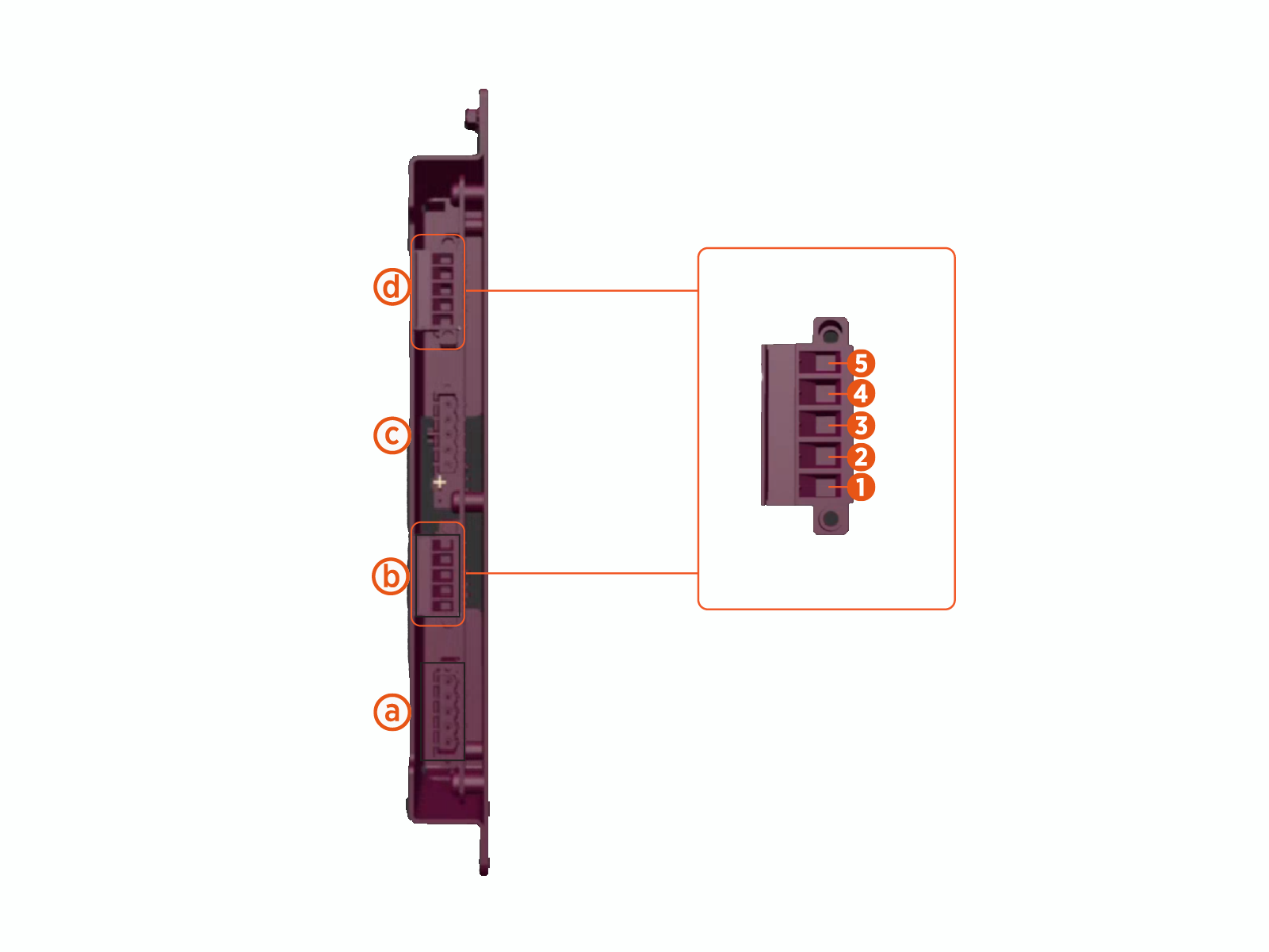
|
Ref |
Allocation |
|---|---|
| (a) |
Terminal A – Not used |
| (b) |
Terminal B – Corresponds to the Power Link connected at EXT B output |
| (c) |
Terminal C – Not used |
| (d) |
Terminal D – Corresponds to the Power Link connected at EXT D output |
Install Jumper Wire
If the Express Solo connects to a Power Link model that requires jumper wire installation at the Safety Hub Board, follow steps below to install a jumper wire at the appropriate terminals of the Safety Hub Board.
The jumper wire is provided with the Power Link.
-
Identify the terminal on the Safety Hub Board. Refer to Identify Safety Hub Board Location, Terminals, and Pin Ports.
-
Fully loosen the captive screws (x2) on the terminal block plug.
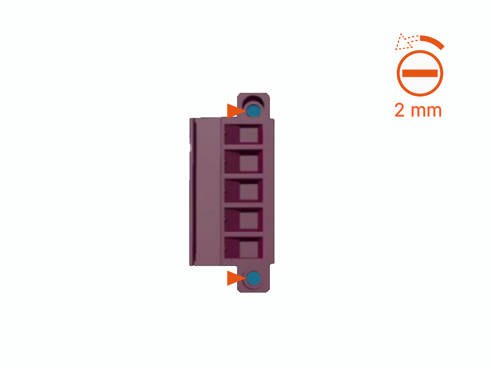
-
Remove terminal block plug from the Safety Hub Board.
-
Install a jumper cable into the plug, using the following steps:
-
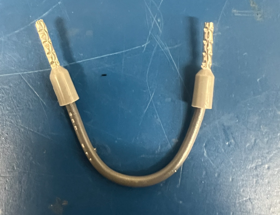
Locate the jumper wire (supplied with the Power Link).
-
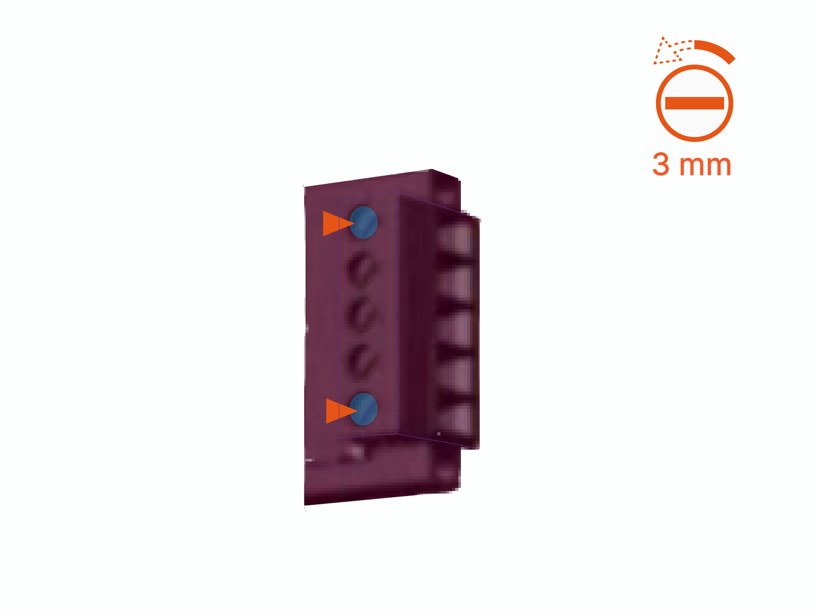
Loosen the set screws for pin ports #1 and #5.
-
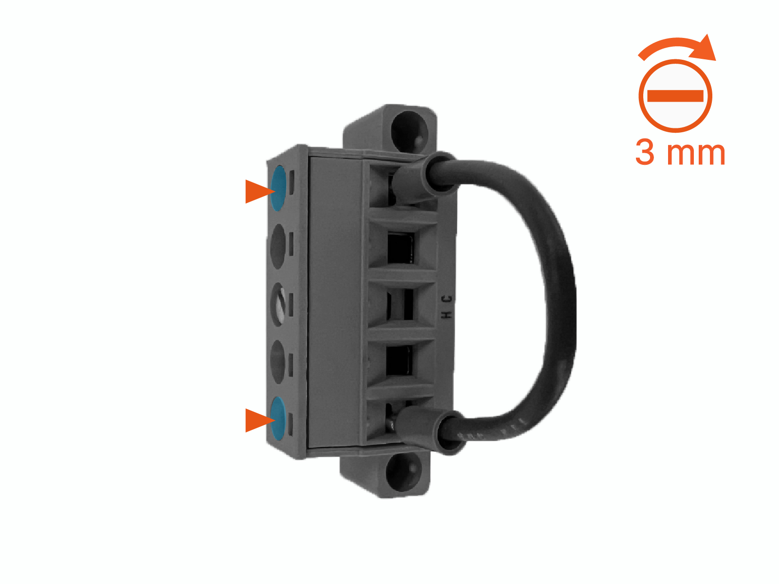
Insert the jumper wire ends into pin ports #1 and #5. Then tighten the set screws to 0.5 Nm (4.4 in-lb). Push-pull to confirm the jumper is secure.
-
-
Reinstall the terminal block plug at the Safety Hub Board. Use a 2 mm flathead screwdriver and tighten the captive screws (x2) to 0.3 Nm (2.7 in-lb).
Connect Shunt Trip Wires
TBD
