Mount Mast
Alternatively, you may use a forklift bracket kit, or a crane with lifting shackles and a spreader bar (constraints may differ among sites).
Parts Needed
To prepare for mast install, find the following parts:
-
Parts from the Mast Installation Parts Crate:
-
1-1/2 in bolt (x10), 1-1/2 in washer (x20), 1-1/2 in nut (x10)
-
Mast ground bar
-
3/8 in bolt (x2), flat washer (x4), dragon tooth washer (x4), lock washer (x2), nut (x2)
-
Knockout cover
-
Knockout cover wedge pins
-
-
Parts from the Mast Components Kit:
-
Controller interface cable (13 m, 42.7 ft)
-
Wi-Fi
 Wireless Fidelity antenna coaxial cable (13 m, 42.7 ft)
 -
RFID
Radio Frequency IDentification antenna coaxial cable (13 m, 42.7 ft)
-
Install Leveling Nuts
-
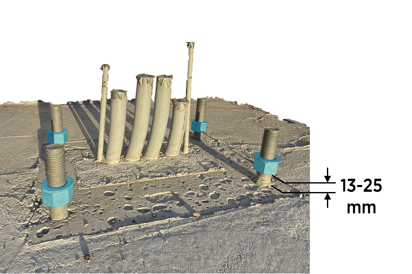
Locate the four embedded anchor bolts for the Pantograph Down Mast. If necessary clean the bolts and concrete surface with a vacuum cleaner and brush.
-
Install a 2-1/4 inch hex nut followed by a 2-1/4 inch washer onto each anchor bolt, leaving 13 - 25 mm (0.5 - 1.0 in) clearance between the foundation surface and the nut bottom.
-
Level the nuts in all directions.

Mount Mast
-
Remove shipping straps securing the mast. Remove protective wrapping from the pole of the mast.
Leave the protective wrapping around the arm of the mast.
-
Locate the hoisting bar on the mast. Fit the crane with a lifting sling and secure the sling straps onto the hoist bar.

-
Gradually lift and position the mast over and above the anchor bolts.

-
Align the mast anchor bolt holes (x4) with the anchor bolts, and slowly lower the mast pole to rest on the leveling nuts.
 with the anchor bolts, and slowly lower the mast pole to rest on the leveling nuts.")
-
Install 2-1/4 inch washer and nut onto each anchor bolt (x4). Tighten to snug tight condition with a 3-1/2 inch socket.
. Tighten to snug tight condition with a 3-1/2 inch socket.")
-
Ensure the mast is level. Adjust leveling nuts if required.

-
Apply Turn of Nut technique to torque anchor bolt top nuts (x4). Use 3-1/2 inch strike wrench.
Be careful not to damage the high voltage (HV High Voltage) DC wires present within the mast. If necessary, pull the wires out through the front access or lower rear vent opening.
. Use 3-1/2 inch strike wrench.")
-
Mark the torqued connections.
-
Release the lifting slings from the hoisting bar.

-
Remove the protective wrapping from the arm of the mast.
Raise and Connect Arm
-
Locate the arm shipping fixture. Attach metal lifting cable sling between the shipping fixture and the crane hook.

-
Lift the crane hook until there is no slack in the sling.
-
Remove pin to release the arm shipping fixture from the support bar.

-
Use the crane to slowly lift the mast arm. Monitor the flexible conduit at the junction between pole and arm to ensure the conduit slides freely and does not catch or chafe.

-
Pause when the arm is nearly horizontal and the two connection plates begin to touch. Check the bolt hole alignment between the arm and pole. If required, use a bull pin or iron workers pry bar to align the bolt holes. Then slowly lift the arm until the connection plates mate completely.
-
Working through the the top and rear openings in the mast, install fasteners one at a time as follows:
-
Install 1-1/2 in bolt with washer into a bolt hole from bottom up.

-
Install 1-1/2 in washer and nut over the bolt. Use a 2-3/8 in socket to turn nut to snug tight condition.

-
-
Apply Turn of Nut technique to torque fasteners. Use a 2-3/8 in socket and follow these procedures:
-
Starting with an outermost pair of diametrically opposing fasteners, torque the fasteners.
-
Torque the other outermost pair of diametrically opposing fasteners.
-
Torque remaining fasteners by working your way inwards in the same fashion.
-
Remove Pivot Hinges
-
Remove pins (x2) from the pivot hinge.
 from the pivot hinge.")
-
Remove the collar (a) and rigging bars (x2) (b).
Each rigging bar weighs 23 kg (51 lb). and rigging bars (x2) (b).")
-
Remove bolts and washers (x12) at the pivot cap plates. Slide cap plates off.
 at the pivot cap plates. Slide cap plates off.")
-
Remove bolts and washers (x12) at the pivot tube assembly. Slide pivot tube assemblies out.
 at the pivot tube assembly. Slide pivot tube assemblies out.")
-
Hold pivot lug to prevent it from falling. Remove the clip to release the pivot lug. Repeat for other pivot lug.

-
Hold pivot yoke to prevent it from falling. From inside the mast column, remove pin to release the pivot yoke. Repeat for other pivot yoke.
Save the pins. They will be used again when installing mast covers and panels.
Remove Arm Shipping Fixture
-
Place wood dunnage below the arm shipping fixture.

-
Remove the pins (x2) securing the arm shipping fixture, allowing the fixture to rest on the wood dunnage.
The shipping fixture weighs 57 kg (125 lb). Use caution when removing the pins and keep hands clear of the area between the shipping fixture and wood dunnage. securing the arm shipping fixture, allowing the fixture to rest on the wood dunnage.")
-
Carefully remove the shipping fixture from the structure.

-
Remove the wood dunnage.

Remove Support Column
-
Brace the support column to prevent it from falling. Remove the pin securing the support column.
The support column weighs 44 kg (96 lb). Ensure the column is supported prior to pin removal.
-
Remove the support column.
Two people are required to safely support the weight of the column during removal.
Open Mast Door
-
Loosen (do not remove) screws (x4) on mast door.
 screws (x4) on mast door.")
-
Quarter turn to unlock door latches (x2).
.")
-
Open the mast door.

Remove Support Bridge
-
Locate the support bridge inside the mast.

-
Hold the support bridge to keep it from falling and remove pins (x4) securing the support bridge.
The support bridge weighs 14.5 kg (32 lb).
 securing the support bridge.")
-
Remove the support bridge.

Install Mast Ground Bar
-
On the front interior face of the mast pole, locate the mast ground bar base.

-
Install the mast ground bar onto the base. Torque fasteners to 19 Nm (14 ft-lb).

-
3/8 x 1-1/4 in bolt
-
3/8 in flat washer
-
Mast ground bar
-
3/8 in dragon tooth washer
-
3/8 in lock washer
-
3/8 in hex nut
-
Install Knockout Cover
-
On the inside of the main access door, slide the knockout cover over two tabs on the door until the cover is flush with the door.

-
Insert wedge pins (x2) to fasten the knockout cover to the door.
 to fasten the knockout cover to the door.")
Pull Low Voltage Cables
-
Familiarize yourself with the cables listed below. Refer to Appendix: Low Voltage Wire Reference.
-
Controller interface cable
-
Wi-Fi
Wireless Fidelity antenna coaxial cable -
RFID
Radio Frequency IDentification antenna coaxial cable
-
-
Label both ends of the coaxial cables to ensure Wi-Fi
Wireless Fidelity and RFID Radio Frequency IDentification antennas are connected correctly at the PD Controller.The provided coaxial cables are interchangeable.
-
Feed the cable ends that will connect to the PD Controller into the front opening of the mast arm. Guide the cables down the mast pole.

-
Stop when the opposite cable ends reach the front opening of the mast arm. At the top access hatch, secure the cables so they do not slide further down into the pole.

