Prepare for Installation
Follow the instructions provided in this topic to prepare Pantograph Down 2000 for installation.
- If the charging station is not installed, commissioned, or serviced by a ChargePoint certified technician using a ChargePoint-approved method, it is excluded from all ChargePoint and other warranties and ChargePoint is not responsible.
- You must be a licensed electrician and complete training at https://www.chargepoint.com/partners/training-certification to become ChargePoint certified and to access ChargePoint's web-based installer tools or ChargePoint Installer app.
Check Site Readiness
To check site readiness, complete this checklist before you install Pantograph Down 2000:
| Pantograph Down 2000 Site Readiness Checklist | ||||
|---|---|---|---|---|
|
☐ | |||
|
☐ | |||
|
☐ | |||
|
☐ | |||
|
☐ |
Electrical Readiness
Refer to the Pantograph Down 2000 Datasheet and Pantograph Down 2000 Site Design Guide at ChargePoint Product Reference Documentation for electrical input and output specifications.
Bring These Tools and Resources
Pantograph Down 2000 requires at least three people for installing the mast and at least two people for installing all other components.
Additionally, the installer must bring the equipment, tools, and materials specified in this section. These are not provided by ChargePoint.
Use appropriately sized tools to torque fasteners.
Use the given torque values to tighten the fasteners.
Ensure that the tools such as torque tool, multimeter, and Ethernet tester are calibrated.
Equipment for Lifting and Installing Mast
|
|
Construction crane
|
|
Mobile elevating work platform (scissor lift) |
|
|
Metal lifting cable sling
|
|
Flat eye web lifting sling (x2)
|
Equipment for Lifting Enclosures and Pantograph
|
|
Forklift with anti-slip forks
|
|
|
Equipment and Tools for Installation
|
|
Paper towel roll |
|
Magnet tray |
|
|
Industrial vacuum cleaner |
|
Wire brush (to remove any residue on anchor bolts) |
|
|
Hard hat |
|
Cut-resistant gloves |
|
|
Safety glasses |
|
Ladder |
|
|
Cable ties |
|
Box cutter |
|
|
Cable puller or fish tape |
|
Measuring tape or other tool to measure height, length, and distance |
|
|
Level |
|
Lockout/tagout equipment |
|
|
Multimeter (meter and probes rated for 1000 V) |
|
Ethernet tester such as a Klein Tools VDV526-052 VDV LAN |
|
|
Conduit cutter (to cut up to 4 in conduits) |
|
Pliers |
|
|
Wire cutters, including Ethernet (Cat6 Shielded Twisted Pair (STP |
|
Wire strippers, including Ethernet (Cat6 STP |
|
|
Lug crimping tool and die |
|
Ethernet (RJ45) connector crimping tool |
|
|
Torque wrench |
|
Torque screwdriver |
|
|
Hex socket set (including 8 mm, 10 mm, 13 mm, 17 mm, 24 mm deep socket, 1/2 in, 9/16 in, 3/4 in, 7/16 in, 7/8 in, 15/16 in, 2-3/8 in, 3-1/2 in) |
|
Hex wrench (10 mm, 5/32 in, 3/16 in, 7/32 in, 7/16 in) |
|
|
Wrench set (including 3/4 in, 5/16 in, 13/16 in, 20 mm, 33 mm, 46 mm, and adjustable) 3-1/2 in strike wrench |
|
Torx screwdriver (T20, T25, T30) |
|
|
T25 Security screwdriver |
|
Flathead screwdriver set (including 2.5 mm and 3.5 mm tip for terminal blocks) |
|
|
Phillips head screwdriver set (including #2) |
|
Torque paint pen |
|
|
Permanent marker |
|
Anti-oxidant joint compound (to make gastight joint between wire and lug) and wire pulling lubricant |
|
|
Weatherproof sealant |
|
Dielectric grease |
|
|
Hydraulic hole punch |
|
Rubber mallet |
|
|
Hand-held drill |
|
Drill bit (3/8 in) |
|
|
Smartphone with internet connectivity |
|
QR |
|
|
ChargePointInstaller app |
|
ChargePoint installer login credentials |
Additional Consumables
The installer must provide the following parts. These parts are not provided by ChargePoint.
-
A 3-1/2 inch strut pipe strap (x1 per Pantograph Down Mast)
-
A water-tight cable gland for the ground wire that exits the Power Link 2000 bottom gland plate and connects to the Pantograph Down Mast (x1 per Power Link 2000)
Wires and Terminations Required for Site
The installer must bring all wires and lugs specified in this section. They are not provided by ChargePoint.
-
For AC and DC high voltage (HV
 High Voltage), high current wiring, use copper or aluminum wires rated for 90 °C (194 °F).
-
AC high current wires can be THHN Thermoplastic High Heat-Resistant Nylon-Coated/THHW Thermoplastic High Heat-Tesistant, Water-Resistant/THW Thermoplastic Heat-Resistant, Water-Resistant-2/THWN-2 based on site condition (dry or wet) and rated for 600 V.
-
DC HV High Voltage wires can be XHHW/XHHW-2 based on site condition (dry or wet) and rated for 1000 V.
-
AC high current wires can be THHN
-
For low voltage (LV Low Voltage) DC wiring, use only copper wires (XHHW/XHHW-2 based on site condition, dry or wet) rated for 1000 V and 75 °C (167 °F).
- For PD Controller 120–277 V AC input wires, use only copper wires rated for 600 V AC and 75 °C (167 °F).
- Use copper lugs for copper wires and aluminum lugs for aluminum wires. The lugs must be nickel, tin, or silver plated compression (not mechanical) lugs. Nickel-plated lugs installed with dielectric grease is recommended.
- All AC and DC high voltage wires must undergo insulation testing as outlined in the High Voltage Wire Insulation Resistance Test Field Guide.
Mast-mount Power Link 2000 input wires
The Power Block DC (HV![]() High Voltage and LV
High Voltage and LV![]() Low Voltage) and Ethernet outputs are the inputs for the Power Link 2000. In some Express Plus architectures, the Power Link 2000 may receive DC (HV
Low Voltage) and Ethernet outputs are the inputs for the Power Link 2000. In some Express Plus architectures, the Power Link 2000 may receive DC (HV![]() High Voltage and LV
High Voltage and LV![]() Low Voltage) power from Power Block(s) via a connection to another Power Link 2000. The Power Link 2000 may also be configured with LV DC
Low Voltage) power from Power Block(s) via a connection to another Power Link 2000. The Power Link 2000 may also be configured with LV DC![]() Low Voltage Direct Current connection with a soft shutdown switch and/or a hardwired Ethernet connection to a network server.
Low Voltage Direct Current connection with a soft shutdown switch and/or a hardwired Ethernet connection to a network server.
|
Input Wire |
Quantity |
Size |
Termination |
|---|---|---|---|
|
HV DC (Max. 500 A per landing) |
Max. 12 wires (three per pole on each landing) |
Upper landings: Max. 150 mm2 (300 MCM)(*) |
Lug: Long barrel and tongue with two holes spaced 44.5 mm (1.75 in) apart and sized for M12 (0.5 in) studs. Max. tongue width: 31 mm (1.25 in) for upper landings, 25.9 mm (1 in) for lower landings. Aluminum lug max. tongue thickness: 10 mm (0.4 in) for upper landings, 5 mm (0.2 in) for lower landings. |
|
Lower landings: Max. 120 mm2 (4/0 AWG |
|||
|
Ground (from Power Block)
|
Max. 3 wires (one from each Power Block) |
Refer to local code for size; Max. 50 mm2 (1/0 AWG |
Lug: Short barrel and tongue with single hole and sized for M6 (0.25 in) stud. |
|
LV DC (from Power Block or another Power Link 2000) |
Max. 4 wires (two wire pairs; each pair has one wire per pole) |
16 mm2 (6 AWG |
Stripped wire end |
|
Ethernet |
Max. 4 cables |
Cat6 STP |
RJ45 connector |
|
Soft shutdown switch(***) |
2 wires |
2.5 mm2 (14 AWG |
Stripped wire end |
Mast-mount Power Link 2000 output wires
The mast-mount Power Link 2000 provides HV DC![]() High Voltage Direct Current output to one pantograph and provides LV DC
High Voltage Direct Current output to one pantograph and provides LV DC![]() Low Voltage Direct Current and Ethernet output to the PD Controller. In some Express Plus architectures, the Power Link 2000 may provide DC (HV
Low Voltage Direct Current and Ethernet output to the PD Controller. In some Express Plus architectures, the Power Link 2000 may provide DC (HV![]() High Voltage and LV
High Voltage and LV![]() Low Voltage) power from Power Block(s) to other Power Link 2000(s).
Low Voltage) power from Power Block(s) to other Power Link 2000(s).
|
Output Wire |
Quantity |
Size |
Termination |
|---|---|---|---|
|
6 wires (three per pole) |
120 mm2 (4/0 AWG |
Lug(**): Long barrel and tongue with two holes spaced 44.5 mm (1.75 in) apart and sized for M12 (0.5 in) studs. Max. tongue width: 31 mm (1.25 in). Aluminum lug max. tongue thickness: 5 mm (0.2 in). |
|
|
High power ground(*) (to pantograph PE) |
1 wire |
50 mm2 (1/0 AWG |
Lug: Short barrel and tongue with single hole sized for M6 (0.25 in) stud. |
|
Ground (to Pantograph Down Mast) |
1 wire |
Refer to local code for size; Max. 50 mm2 (1/0 AWG |
Lug: Short barrel and tongue with single hole sized for M6 (0.25 in) stud. |
|
LV DC (to another Power Link 2000) |
Max. 4 wires (two wire pairs; each pair has one wire per pole) |
16 mm2 (6 AWG |
Stripped wire end |
|
LV DC (to PD Controller) |
This wire pair is provided with the mast-mount Power Link 2000. The wire ships pre-terminated for connection within the Power Link 2000. |
||
|
Chassis ground (to PD Controller) |
1 wire |
4 mm2 (12 AWG |
Ring terminal: Sized for M6 (0.25 in) stud. |
|
Ethernet |
1 cable |
Cat6 STP |
RJ45 connector, shielded |
PD Controller Wires
Each PD Controller is configured with AC input from the site as well a LV DC![]() Low Voltage Direct Current, chassis ground, and Ethernet connection from a Power Link 2000. Allowed quantity, size, and terminations for these wires are listed below. Check the site plan for site specific wire specifications.
Low Voltage Direct Current, chassis ground, and Ethernet connection from a Power Link 2000. Allowed quantity, size, and terminations for these wires are listed below. Check the site plan for site specific wire specifications.
|
Wire |
Quantity |
Size |
Termination |
|---|---|---|---|
|
120-277 V AC input |
2 wires (one per pole) |
Size based on branch circuit breaker; Max. 16 mm2 (6 AWG |
Stripped wire end |
|
AC ground |
1 wire |
Size based on branch circuit breaker; Max. 16 mm2 (6 AWG |
Stripped wire end |
|
LV DC |
|||
|
Ethernet input |
RJ45 connector, unshielded |
||
|
Chassis ground |
Stripped wire end |
||
Schunk SLS 201.102 pantograph wires
The Schunk SLS 201.102 pantograph is configured with HV DC![]() High Voltage Direct Current input and high power ground connection from a Power Link 2000. It also has a ground connection from the Pantograph Down Mast. Allowed quantity, size, and terminations for these wires are listed below. Check the site plan for site specific wire specifications.
High Voltage Direct Current input and high power ground connection from a Power Link 2000. It also has a ground connection from the Pantograph Down Mast. Allowed quantity, size, and terminations for these wires are listed below. Check the site plan for site specific wire specifications.
|
Wire |
Max. Wire Quantity and Size |
Termination |
|---|---|---|
|
HV DC (from Power Link 2000) |
Lug: Single hole lug and sized for M10 bolt. |
|
|
High power ground (PE) (from Power Link 2000) |
Lug: Single hole lug and sized for M10 bolt. |
|
|
Ground (from Pantograph Down Mast) |
Ring terminal: Sized for M8 bolt. |
Pantograph Down Mast wires
The Pantograph Down Mast is configured with a ground connection from the Power Link 2000. Depending on site requirements, it may also be connected to a maximum of two grounding rods. Allowed quantity, size, and terminations for these wires are listed below. Check the site plan for site specific wire specifications.
|
Wire |
Quantity |
Size |
Termination |
|---|---|---|---|
|
Ground (from grounding rods)
|
Max. 2 wires |
Refer to local code for size; Max. 50 mm2 (1/0 AWG |
Lug: Single hole and sized for 3/8 in bolt. |
|
Ground (from Power Link 2000) |
1 wire |
Lug: Single hole and sized for 3/8 in bolt. |
|
|
Ground (to pantograph frame) |
1 wire |
Refer to local code for size; Max. 50 mm2 (1/0 AWG |
Ring terminal: Sized for M8 bolt. |
Tightening Torques
Power Link 2000
| Component | Component Material | Fastener | Tool | Torque |
|---|---|---|---|---|
|
— |
— |
2.5 mm flathead screwdriver |
0.6 Nm (5.3 in-lb) |
|
|
— |
— |
3.5 mm flathead screwdriver |
0.7 Nm (6.2 in-lb) |
|
|
LV DC terminal set screws (for output to Power Block or other Power Link 2000) |
— |
— |
3.5 mm flathead screwdriver |
1.5 Nm (13.3 in-lb) |
| Metal | M5 |
T25 Security |
4.5 Nm (40 in-lb) | |
|
8 mm socket |
||||
|
Metal |
M6 |
T30 Torx |
5.6 Nm (50 in-lb) |
|
|
10 mm socket |
||||
|
Metal |
M10 |
17 mm socket |
19 Nm (14 ft-lb) |
|
Mounting base fasteners |
Metal | 1/2 in | 3/4 in socket | 50 Nm (37 ft-lb) |
PD Controller
| Component | Component Material | Fastener | Tool | Torque |
|---|---|---|---|---|
| — | — |
5/16 in wrench |
0.45 Nm (4 in-lb) |
|
| — | — | |||
| — | — |
3.5 mm flathead screwdriver |
1.7 Nm (15 in-lb) |
|
| — | — |
#2 Phillips screwdriver
|
2.4 Nm (21.2 in-lb) |
|
| — | — |
2.8 Nm (24.8 in-lb) |
||
| — | — |
4 Nm (35.4 in-lb) |
||
| — | — |
33 mm wrench
|
4.5 Nm (40 in-lb)
|
|
| — | — |
46 mm wrench
|
||
|
— |
— |
33 mm wrench
|
7.9 Nm (70 in-lb) |
|
|
— |
— |
46 mm wrench |
10.2 Nm (90 in-lb) |
|
Enclosure mounting bolts |
Metal | 5/16 in | 1/2 in socket | 10 Nm (90 in-lb) |
Unistrut mounting fasteners |
Metal | 1/2 in | 3/4 in socket | 50 Nm (37 ft-lb) |
Auxiliary Components
| Component | Component Material | Fastener | Tool | Torque |
|---|---|---|---|---|
| — | — |
13/16 hex wrench
|
1.5 Nm (13.3 in-lb) |
|
| — | — | |||
|
Metal |
M5 |
8 mm socket |
4.5 Nm (40 in-lb)
|
|
|
Metal |
||||
|
Metal |
M6 |
10 mm socket |
5.6 Nm (50 in-lb)
|
|
|
Metal |
||||
|
Metal |
||||
|
Metal |
||||
|
Auxiliary component frame, side cover nuts (along cover length) |
Metal |
|||
|
Metal |
M16 |
24 mm deep socket |
94.9 Nm (70 ft-lb) |
Schunk SLS 201.102 Pantograph
| Component | Component Material | Fastener | Tool | Torque |
|---|---|---|---|---|
| — | — | 7/16 in | 4.7 Nm (42 in-lb) | |
| — | — |
20 mm wrench |
1.5 Nm (13.3 in-lb) |
|
|
Metal |
M8 |
13 mm socket |
12.2 Nm (108 in-lb) |
|
| Metal | M10 | 13 mm and 17 mm socket | 19 Nm (14 ft-lb) | |
| Metal | 5/8 in | 15/16 in socket | 99 Nm (73 ft-lb) |
Pantograph Down Mast
| Component | Component Material | Fastener | Tool | Torque |
|---|---|---|---|---|
|
(for pantograph access cover, hinge access cover, mast arm endcap, and vent panels) |
Metal | 3/8 in | 7/32 in hex | 5.6 Nm (50 in-lb) |
| Metal | M6 | T25 Torx and 10 mm socket | 5.6 Nm (50 in-lb) | |
| Metal | M8 | 13 mm socket | 15 Nm (133 in-lb) | |
| Metal | 3/8 in | 9/16 in socket | 19 Nm (14 ft-lb) | |
| Metal | 1-1/2 in | 2-3/8 in socket | Turn of Nut Technique | |
| Metal | 2-1/4 in | 3-1/2 in strike wrench |
Pantograph Down 2000 Packages
Leave components in the shipping crate until needed. When removing, protect them from damage (such as scratches) by placing them flat on a blanket or tarp, face up. Do not stand up cover panels, as they may be knocked or blown over. Cover charging connectors to prevent damage or ingress.
For any missing component, contact chargepoint.com/support.
Package Dimensions and Weights
| Package | Dimensions (LxWxH) | Max. Weight |
|---|---|---|
|
Pantograph Down Mast |
Varies. The mast arrives on a flat bed truck. |
3175 kg (7000 lb) |
|
Mast installation parts crate |
0.9 x 0.68 x 0.47 m (35.5 x 27 x 18.5 in) |
113 kg (250 lb) |
|
Mast panels and covers crate |
0.86 x 0.74 x 0.55 m (34 x 29.3 x 21.5 in) |
113 kg (250 lb) |
|
Mast Components Kit |
Not available |
Not available |
|
Power Link 2000 |
1.52 x 1.14 x 0.51 m (60 x 45 x 20 in) |
182 kg (400 lb) |
|
PD Controller |
0.8 x 0.79 x 0.33 m (31.5 x 31 x 13 in) |
37 kg (81 lb) |
|
Schunk SLS 201.102 |
2.44 x 1.22 x 1.22 m (96 x 48 x 48 in) |
340 kg (750 lb) |
|
Schunk SLS 201.102 Auxiliary Components Kit |
2.71 x 0.93 x 0.34 m (106.8 x 36.3 x 13.3 in) |
75 kg (165 lb) |
|
Ethernet to USB |
0.3 x 0.39 x 0.22 m (11.81 x 15.35 x 8.66 in) |
1.4 kg (3 lbs) |
Pantograph Down Mast
The Pantograph Down Mast ships to site on a flatbed truck, along with two parts crates.
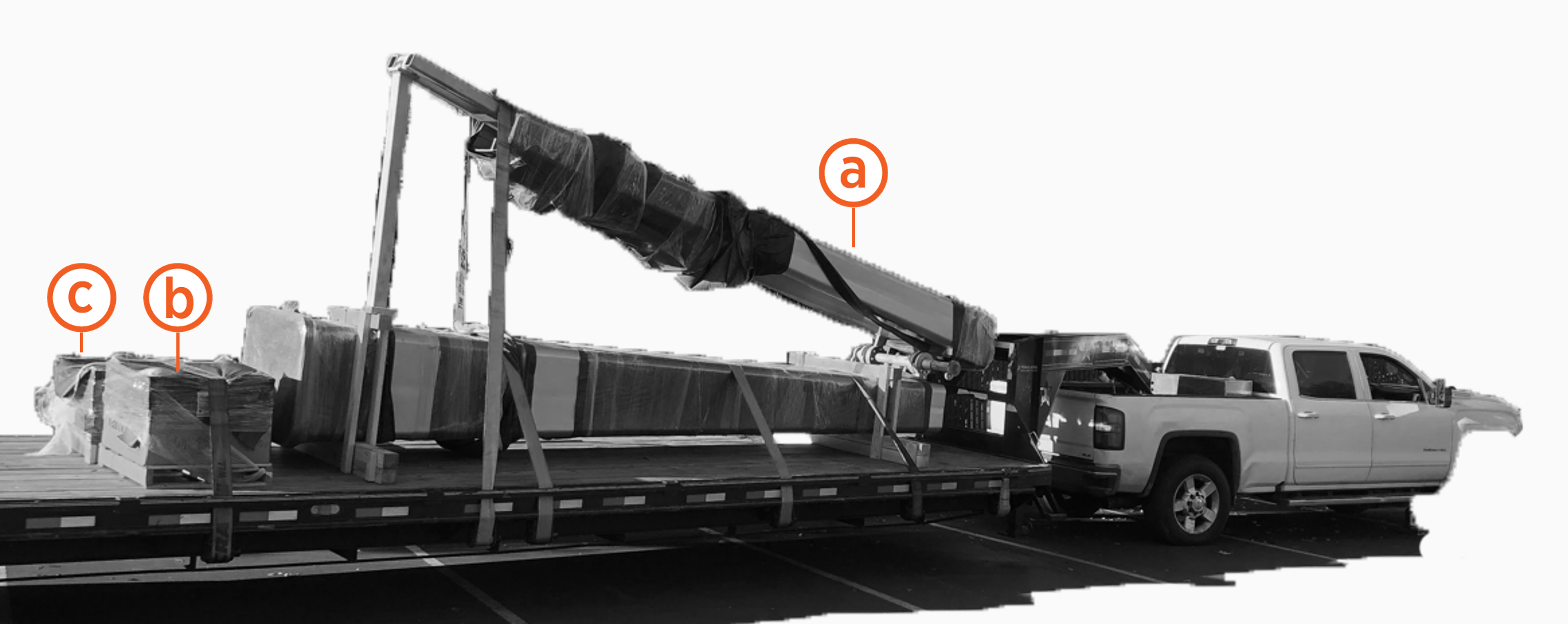
-
Mast
-
Installation parts crate
-
Panels and covers crate
Installation Parts Crate
Images are not exact to scale.
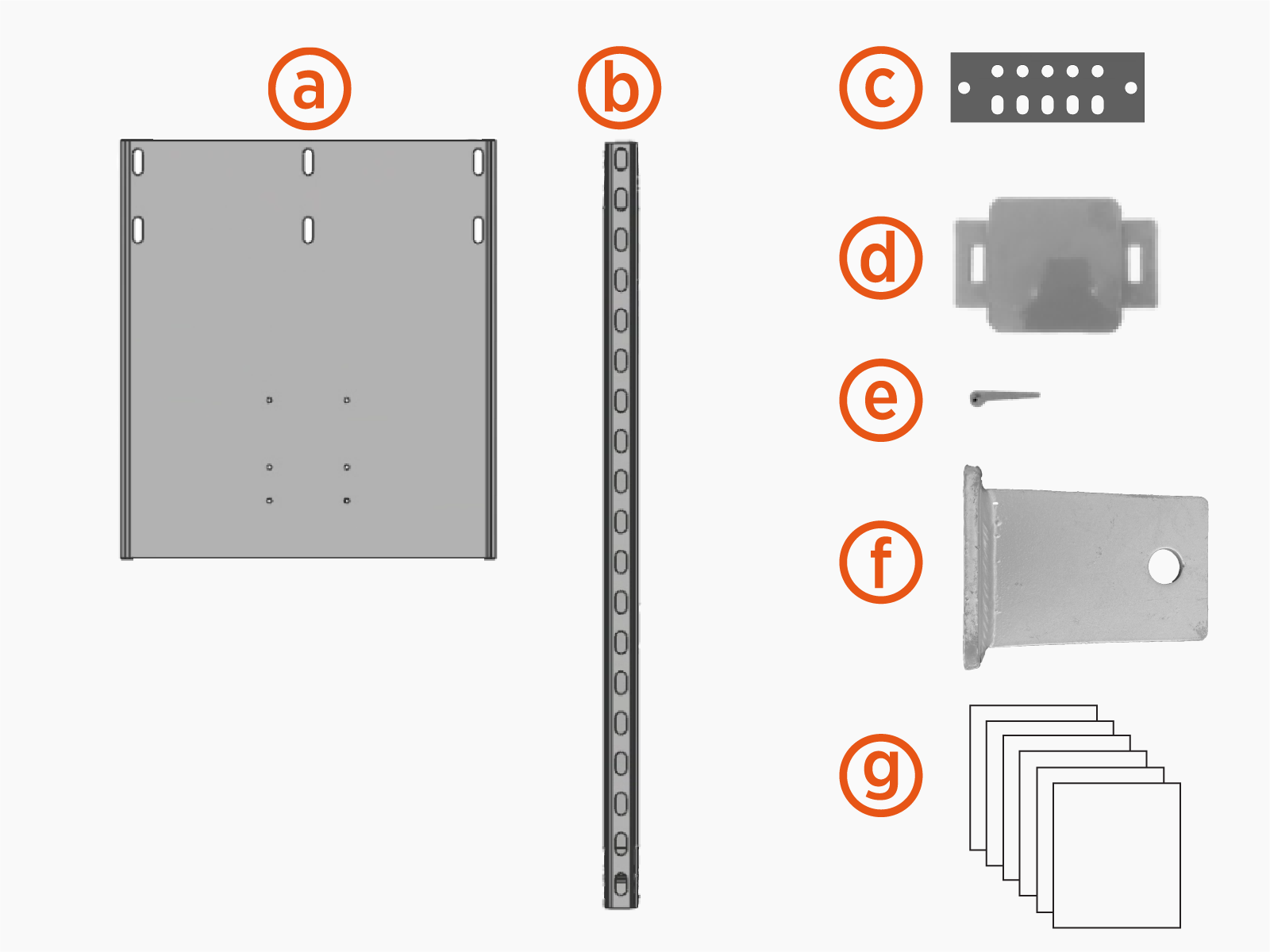
-
Power Link 2000 mounting base
-
PD Controller mounting unistruts (x2)
-
Mast ground bar
-
Knockout cover
-
Knockout cover wedge pins (x2)
-
Pivot hinge plugs (x2)
-
Bags with fasteners and hardware:
-
Fasteners for securing mast arm to pole: 1-1/2 x 8 in bolts (x10), 1-1/2 in washers (x20), 1-1/2 in nuts (x10)
-
Fasteners for securing Power Link 2000 mounting base: 1/2 in bolts (x6), 1/2 in washer (x6), 1/2 in nuts (x6)
-
Fasteners for securing Power Link 2000 to mounting base: M6 x 25 mm screws (x8)
-
Fasteners for securing PD Controller mounting unistruts: 1/2 in bolts (x4), 1/2 in washers (x4), 1/2 in nuts (x4)
-
Fasteners for securing PD Controller to unistruts: 5/16 x 1-1/4 in bolts (x4), 5/16 in washers (x4), 5/16 in spring nuts (x4)
-
Fasteners for securing Schunk SLS 201.102 pantograph on mast: 5/8 x 2 in bolt (x4). 5/8 in flat washer (x4), 5/8 in lock washer (x4), 5/8 in hex nut (x4)
-
Fasteners for securing mast ground bar: 3/8 x 1-1/4 in bolts (x2), 3/8 in flat washers (x4), 3/8 in dragon tooth washers (x4), 3/8 in lock washers (x2), 3/8 in hex nuts (x2)
-
Lanyards (x3) with caribiner clips attached at each end
-
Fasteners for securing mast covers and panels: 3/8 x 1-1/4 in button head screws (x16)
-
Panels and Covers Crate
Images are not exact to scale.
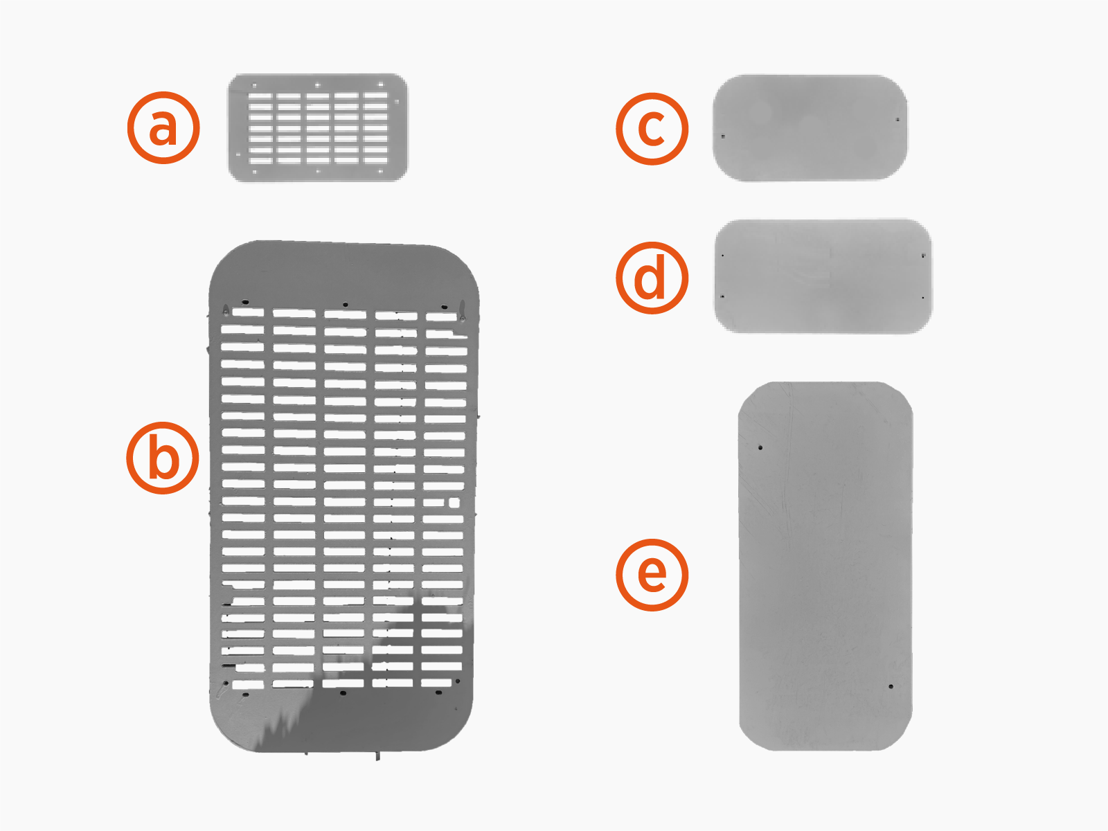
-
Upper vent panels (x2)
-
Lower rear vent panel
-
Hinge top access cover
-
Arm end cap
-
Pantograph top access cover
Mast Components Kit
-
Controller interface cable (13 m, 42.7 ft)
-
Wi-Fi antenna coaxial cable (13 m, 42.7 ft)
-
RFID antenna coaxial cable (13 m, 42.7 ft)
-
Mesh screens, small (x2)
-
Bags with fasteners:
-
Fasteners for securing door window cover: M4 screws and M4 oversized washers (x10 each)
-
Fasteners for securing mesh screens to covers: M6 screws and M6 nuts (x18 each)
-
Fasteners for landing ground wire at pantograph frame: M8 bolt and M8 flange nut (x1 each)
-
Fasteners for landing ground wires at mast ground bar: 3/8 in flange bolts, 3/8 in flange nuts, and 3/8 in external tooth washers (x5 each)
-
-
Cable ties (x2)
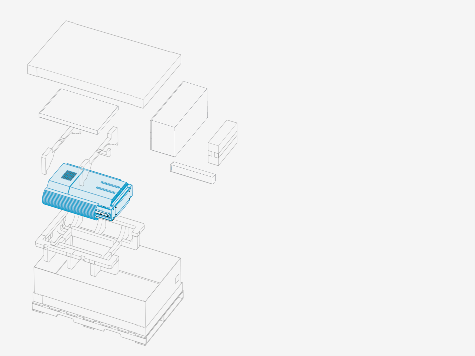
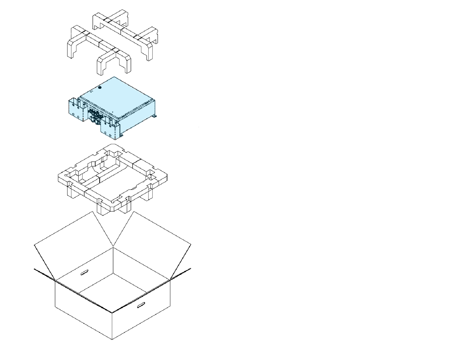
Power Link 2000 Package
PD Controller Package
Schunk SLS 201.102 Package
The pantograph ships crated and secured on a pallet.


-
Mounting frame side cover, right
-
Mounting frame rail, right
-
Mounting frame side cover, left
-
Mounting frame rail, left
-
RFID
Radio Frequency IDentification antenna assembly -
Status LED and cable
-
Mounting frame cover, front
-
Controller interface cable (5 m, 16.4 ft)
-
Mounting frame cover, rear
-
Wi-Fi
Wireless Fidelity and RFID Radio Frequency IDentification antenna coaxial cables (x2) (5m, 16.4 ft each) -
Hardware box with:
-
Ground wire (0.5 m, 1.6 ft)
-
M8 bolt and M8 nut (x1 each)
-
M10 bolts and M10 flange nuts (x5 each)
-
M16 bolts and M16 nuts (x4 each)
-
Wire terminal operating tool
-
Cable ties (x9)
-
-
Wi-Fi
Wireless Fidelity antenna assembly
Disconnect Power
To disconnect power, complete the following steps:
- Before any procedure, disconnect the power.
- Follow local code and site lockout/tagout procedure to de-energize the station.
- Wait for energy to dissipate (approximately five minutes).
- Keep power off until all covers and panels are reinstalled and the work is complete.
-
Disconnect power at the site electrical panel.
Follow standard practice and local code to de-energize the applicable circuit and lock out/tag out the disconnect before proceeding.
-
Use a multimeter to test that the unit is de-energized.
