Build the Pedestal
To build the pedestal, follow these steps:
Check the Box Contents
-
Gather the four lock nuts and strain relief hole plug remaining from Box #3, the Station Mount Kit.
-
Box #4, the Cable Management Kit, contains the CMK
 Cable Management Kit. Identify the box but do not open it until later in this section.
 -
Ensure Box #2, the Pedestal Mount Kit, has all components listed as follows.
|
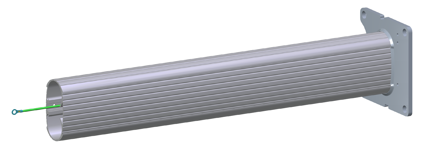
Pedestal column (1) |
|
|
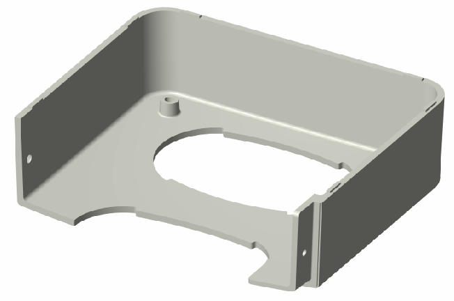
Front bolt cover (1) |
|
|
Rear bolt cover (1) |
|
|
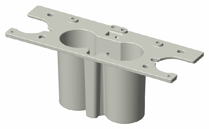
Head bracket (1) |
|
|
Installation kit (1) |
Contains:
|

Prepare the Head Bracket and Bolt Covers
-
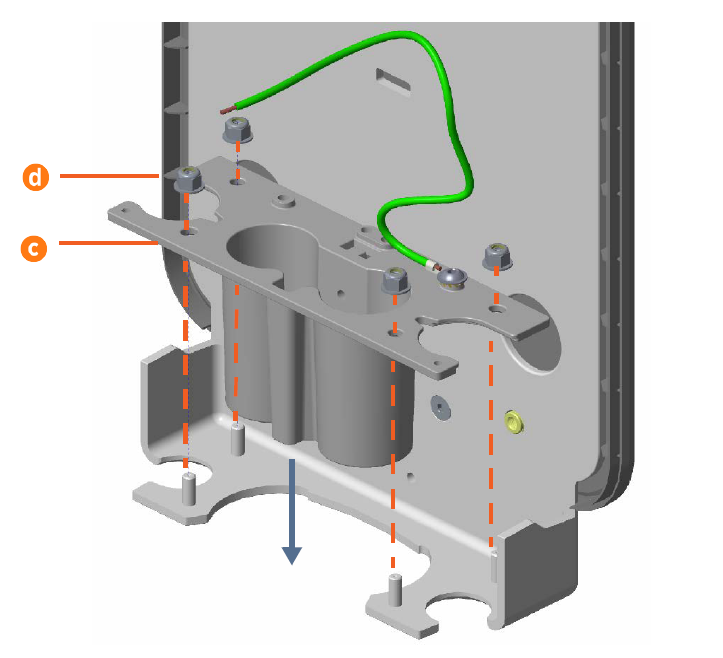
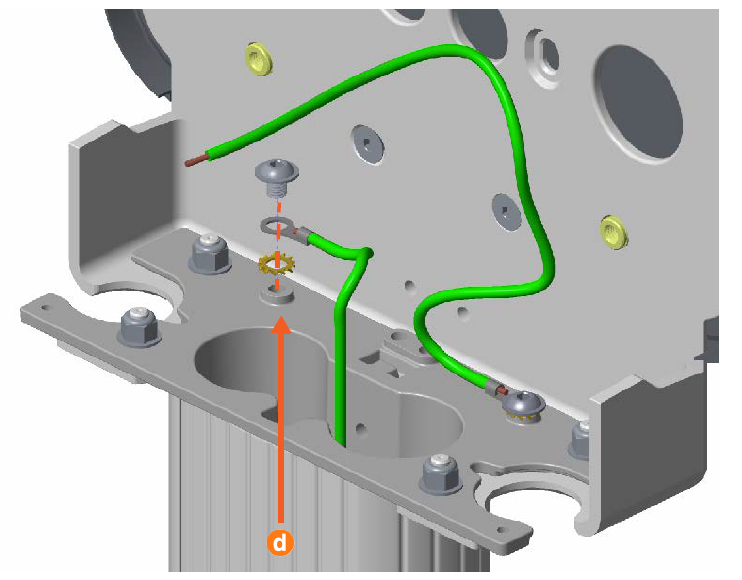
Using a 5 mm hex driver, connect the 635 mm grounding cable (a) from the pedestal box to the head bracket (b) with a 10 mm M8 button head cap screw and an M8 toothed washer. Tighten the screw to 16 Nm.

-
Fit the head bracket (c) into place on the support bracket, then use a 13 mm wrench to secure an M8 lock nut (d) onto each bolt. Tighten the nuts to 16 Nm.
-
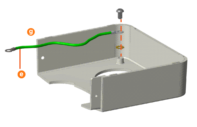
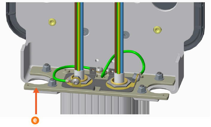
Using a 5 mm hex driver, connect 241 mm grounding cables (e) to the front bolt cover (f) and rear bolt cover (g) with 10 mm M8 button head cap screws and M8 toothed washers. Tighten the screws to 16 Nm.

Mount the Pedestal
-
Each mounting bolt should already have two M16 nuts and two M16 washers threaded onto it. Remove the top nut and top washer from each mounting bolt. Put them somewhere safe to use in a later step.
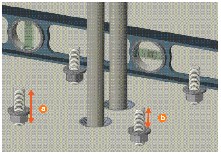
Each mounting bolt must extend a maximum of 55 mm above the ground (a). Trim the mounting bolts if required. -
Adjust the remaining nuts and washers so that 35 mm of mounting bolt is exposed above each washer (b). Use a spirit level and adjust the height of the nuts as required to ensure the four washers are completely level with each other.
-
Feed the power cables into the pedestal. (If you are installing a single port charging station, there is only one power cable.)
-
Carefully lower the pedestal onto the mounting bolts, feeding the power cables through until they come out the top of the pedestal.
-
UK installers only: Mark the power cables where they exit the top of the pedestal, then remove the pedestal temporarily. Strip the cables and install the cable gland and grounding plate. Replace the pedestal and continue with the next step.
-
Using the fasteners you removed above, install an M16 washer and M16 nut onto each mounting bolt.
-
Adjust the lower nuts as necessary to ensure the pedestal column is fully level.
-
Tighten the nuts to at least 160 Nm.
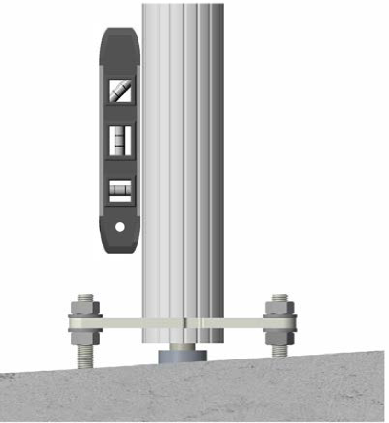
Ensure the pedestal and its base are fully level by positioning a spirit level at various locations on the pedestal above each bolt. Adjust the nuts beneath the base plate if necessary.

Prepare the CMK
Locate Box #4, the Cable Management Kit (CMK![]() Cable Management Kit).
Cable Management Kit).
-
Remove the CMK
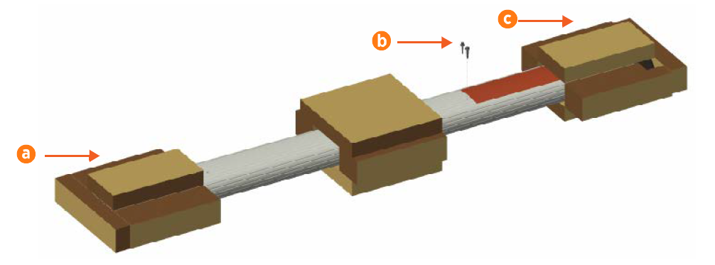
Cable Management Kit from the box and place it carefully on padded ground covering with its base (a) close to the installation site.Do not unwrap the ropes. -
Remove and discard the two 10 mm drive shipping screws (b) from the front face of the CMK
Cable Management Kit.When you remove the shipping screws, the counterweights are free to move in either direction. To prevent damage or injury, always carry the assembly with the top end higher than the bottom end. -
Remove the packaging.
-
Leave the CMK
Cable Management Kit horizontal on the ground to be installed later in this section.
Build the Pedestal
-
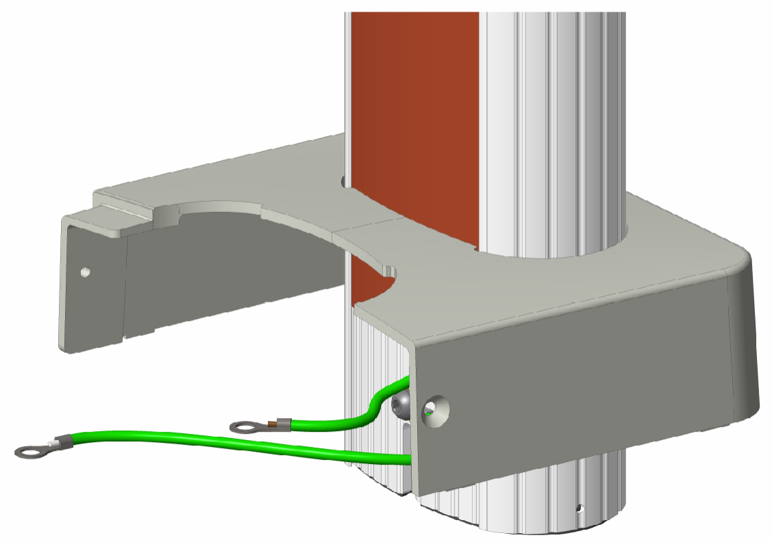
Using a 5 mm hex driver, a 10 mm M8 button head cap screw, and an M8 toothed washer, connect the grounding cable (a) from the front bolt cover (b) to the far- left hole on the base of the pedestal column (c). Tighten the screw to 16 Nm.
-
Find the pre-installed grounding cable inside the top of the pedestal column (d). Lift the assembled station mounting bracket and carefully guide that grounding cable and the power cables through the opening in the bottom of the head bracket.

-
Lower the assembled station mounting bracket onto the pedestal, carefully fitting the head bracket down into the column.
-
Use a T30 Torx driver and two 10 mm M8 button head cap screws to secure it in place. Tighten the screws to 16 Nm.
-
Place the rear bolt cover beside the pedestal. Carefully lift the CMK
Cable Management Kit to a vertical position, top up, then gently lower it into the rear bolt cover.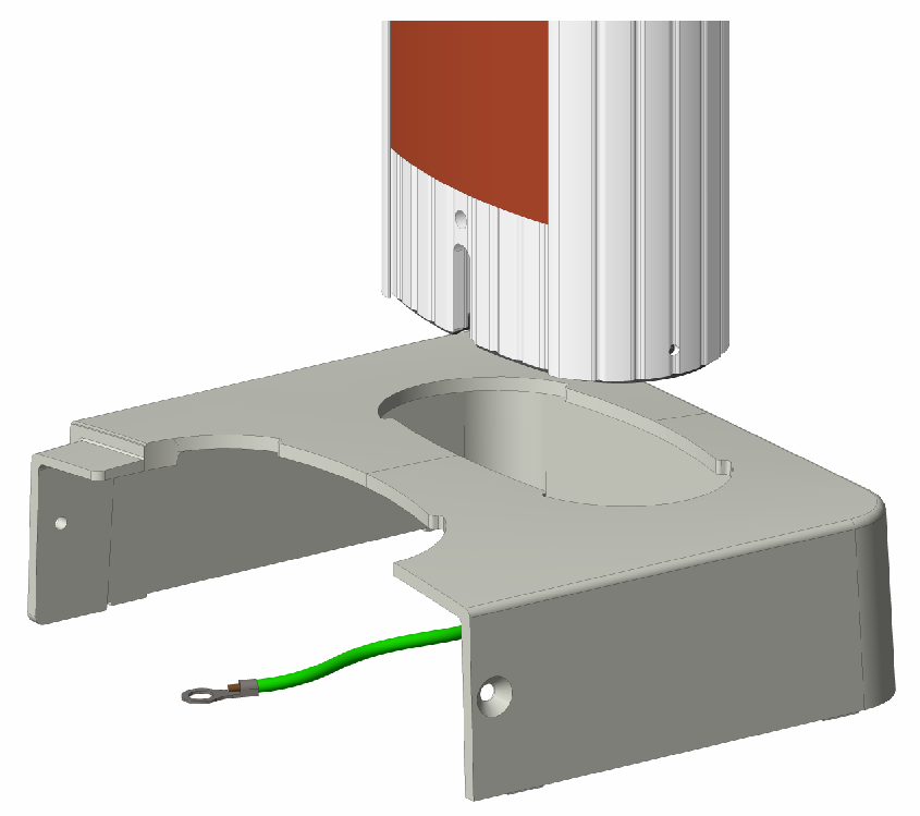
-
Carefully, without scratching any components, slide the bolt cover up the CMK
Cable Management Kit. -
Using a 5 mm hex driver, a 10 mm M8 button head cap screw, and an M8 toothed washer, connect a 241 mm grounding cable to the CMK
Cable Management Kit. Tighten the screw to 16 Nm.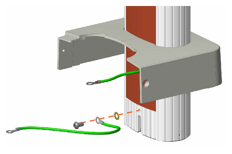
-
Ensure the loose ends of the grounding cables are accessible.
-
Carefully move the rear bolt cover and CMK
Cable Management Kit behind the pedestal. -
Lift the CMK
Cable Management Kit and slowly fit it into the pedestal base plate so that its front notch (a) fits over the T-notch in the base plate (b).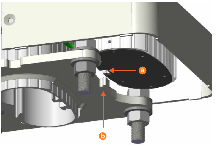
-
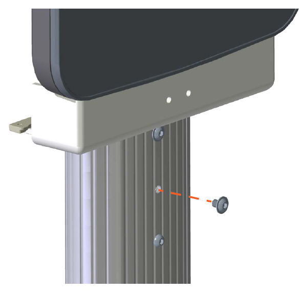
Fit the upper part of the CMK
Cable Management Kit into the clamps on the back of the station mount bracket, as shown at right.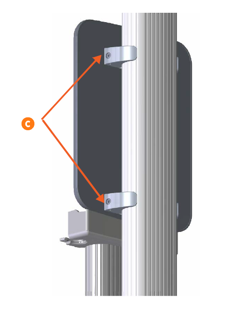
-
While one person holds the CMK
Cable Management Kit in place, use a 6 mm hex driver to tighten the ends of the clamps (c) around the column. Tighten the screws to 16 Nm. -
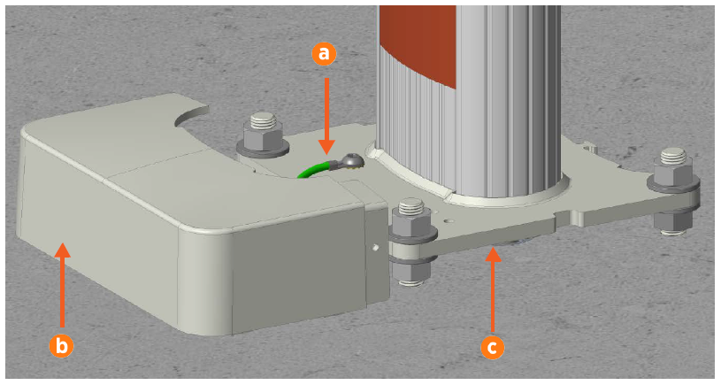
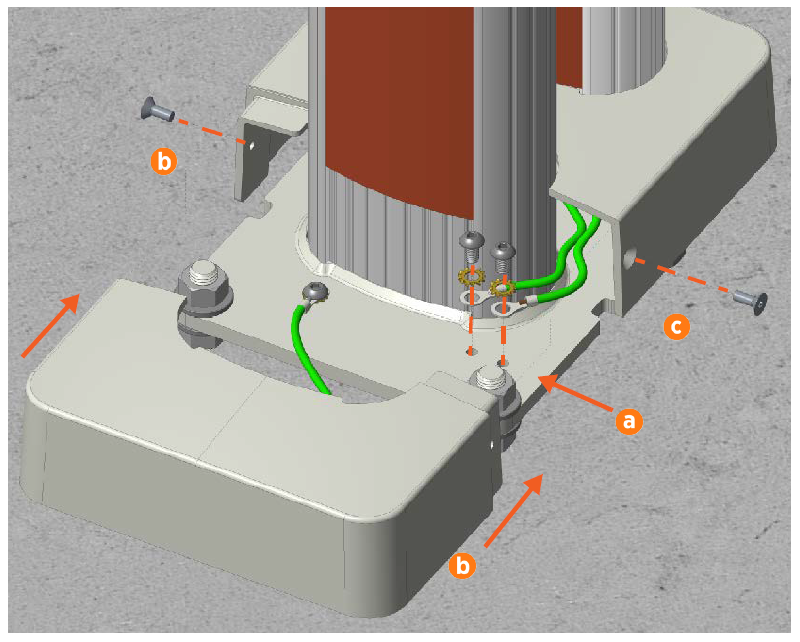
Using a screwdriver with a 5 mm hex driver, a 10 mm M8 button head cap screw, and a toothed washer, connect each loose grounding cable to the pedestal base plate (a). Tighten the screws to 16 Nm.
-
Fit the front bolt cover (b) around the pedestal and over the base plate.
-
Use a T30 tamper-resistant Torx driver and two 16 mm M6 screws to secure the bolt covers together (c). Tighten the screws to 6.5 Nm.
-
Using a driver with a 5 mm hex driver, a 10 mm M8 button head cap screw, and a toothed washer, connect the pre-installed grounding cable inside the pedestal column to the head bracket (d). Tighten the screw to 16 Nm.
-
UK installers only: Use the grounding cable, M8 button head screws, and toothed washers included in the grounding kit box to connect the cable gland to any available hole in the head bracket.
-
If the charging station is a single port station, use the strain relief hole plug to seal the left-side hole (e) in the head bracket.
