Electrical Design
The wall mount CP4000 installation uses surface mount wiring. The pedestal mount CP4000 installation requires service wiring installed underground. (If a pedestal mount installation requires surface run conduit, contact ChargePoint before beginning work to obtain an approved installation method.) Conduit and wire size are determined based on the length of runs from the electrical panel to the station location. Service wiring must be run through conduit to comply with local electrical codes. Consult national and local codes or a project engineer to determine the grade, quality, and size of the conduit or cable. The CP4000 Concrete Mount Kit accommodates service wiring through the flare, conduit, or locally appropriate wiring method.
Power Supply Requirements
Typically, 16 mm2 insulated electrical wire is used, depending upon the rating of the circuit and the distance between the electrical panel and the charging station. The cable entering the station must be less than 25 mm in diameter. For higher demand, you must feed the station with two circuits, each with a maximum diameter of 25 mm.
When planning multiple EV![]() Electric Vehicle charging stations, it is best practice to separate non-continuous from continuous loads, with all branch circuits for EV
Electric Vehicle charging stations, it is best practice to separate non-continuous from continuous loads, with all branch circuits for EV![]() Electric Vehicle charging on a dedicated electrical panel assembly with adequate circuit breakers. When sizing new electrical panels dedicated for EV
Electric Vehicle charging on a dedicated electrical panel assembly with adequate circuit breakers. When sizing new electrical panels dedicated for EV![]() Electric Vehicle charging, all branch circuits must support continuous load.
Electric Vehicle charging, all branch circuits must support continuous load.
Conduit
The outside diameter of conduit must not exceed the sizes called out in the conduit layout drawing: 45 mm. Conduit stub-ups must not extend higher than 660 mm above grade.
For wall mounted stations, flex conduit must be used to bring the wire to the station.
Wiring Requirements
For full product specifications, refer to the CP4000 Datasheet. Using that data, ensure that the installation location is equipped with service wiring that supports the CP4000’s power requirements:
-
AC conductors (L1, L2, L3)
-
Neutral
-
Ground conductor
When pulling electrical wiring for CP4000 pedestal mount, ensure at least 1.5 m of wire remains above grade.
When pulling electrical for wall mounted stations, the conduit and wire must be brought to the location where the stations will be mounted. Flex conduit may be used to bring the wire to the station. The CP4000 has two M32L cable glands in the bottom of the charging station and two rubber knockouts in the rear. For wall mounted installations, the cable can be brought in from the rear or bottom of the station. For pedestal installations, the wiring must be brought from the bottom.
Standard Wiring Options
|
Output |
Input Circuits |
Panel Breaker Required |
Breakers Required |
|---|---|---|---|
|
Single Port Stations |
|||
|
22 kW |
1 |
3-phase 32 A x 1 |
1 |
|
11 kW |
1 |
3-phase 16 A x 1 |
1 |
|
7.4 kW |
1 |
1-phase 32 A x 1 |
1 |
|
3.7 kW |
1 |
1-phase 16 A x 1 |
1 |
|
Dual Port Stations |
|||
|
22 kW |
2 |
3-phase 32 A x 2 |
2 |
|
11 kW |
2 |
3-phase 16 A x 2 |
2 |
|
7.4 kW |
2 |
1-phase 32 A x 2 |
2 |
|
3.7 kW |
2 |
1-phase 16 A x 2 |
2 |
Standard Wiring, Single Port Station
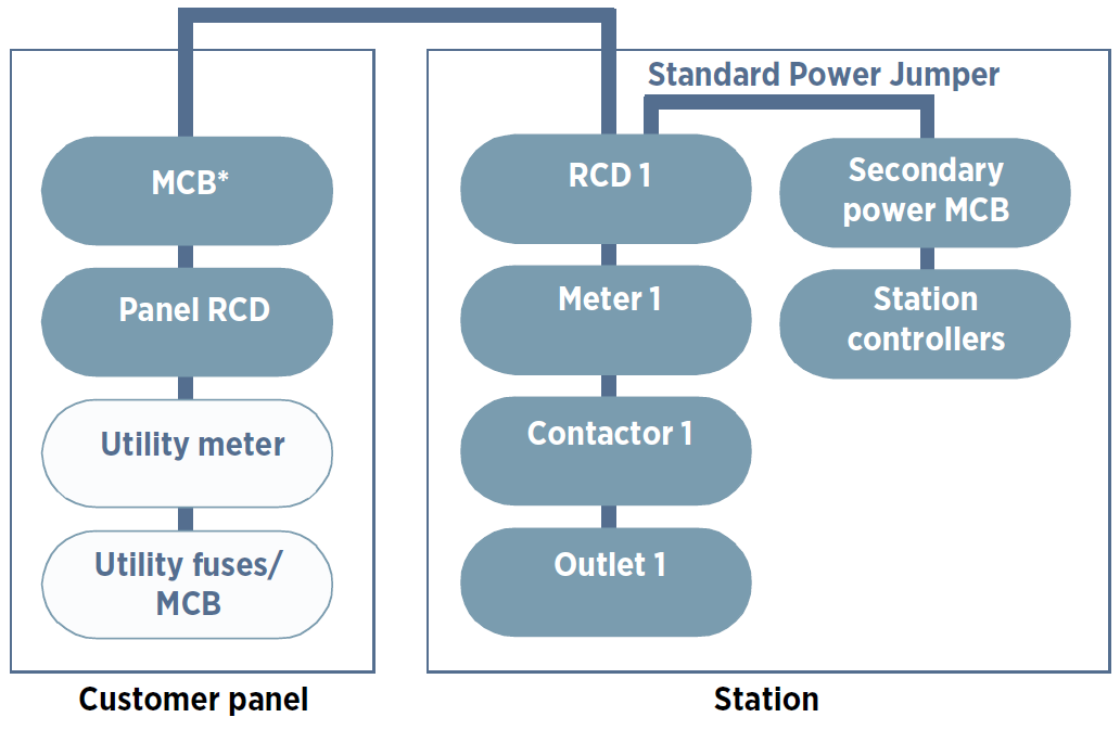
*MCB![]() Miniature Circuit Breaker: Miniature Circuit Breaker
Miniature Circuit Breaker: Miniature Circuit Breaker
Three Phase Wiring
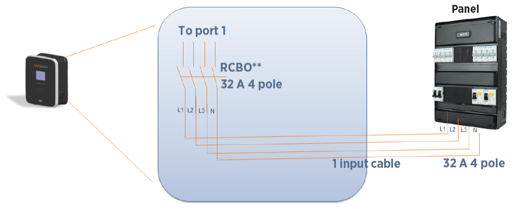
**RCBO![]() Residual Current Breaker with Overload Protection: Residual-Current Circuit Breaker with Overcurrent Protection
Residual Current Breaker with Overload Protection: Residual-Current Circuit Breaker with Overcurrent Protection
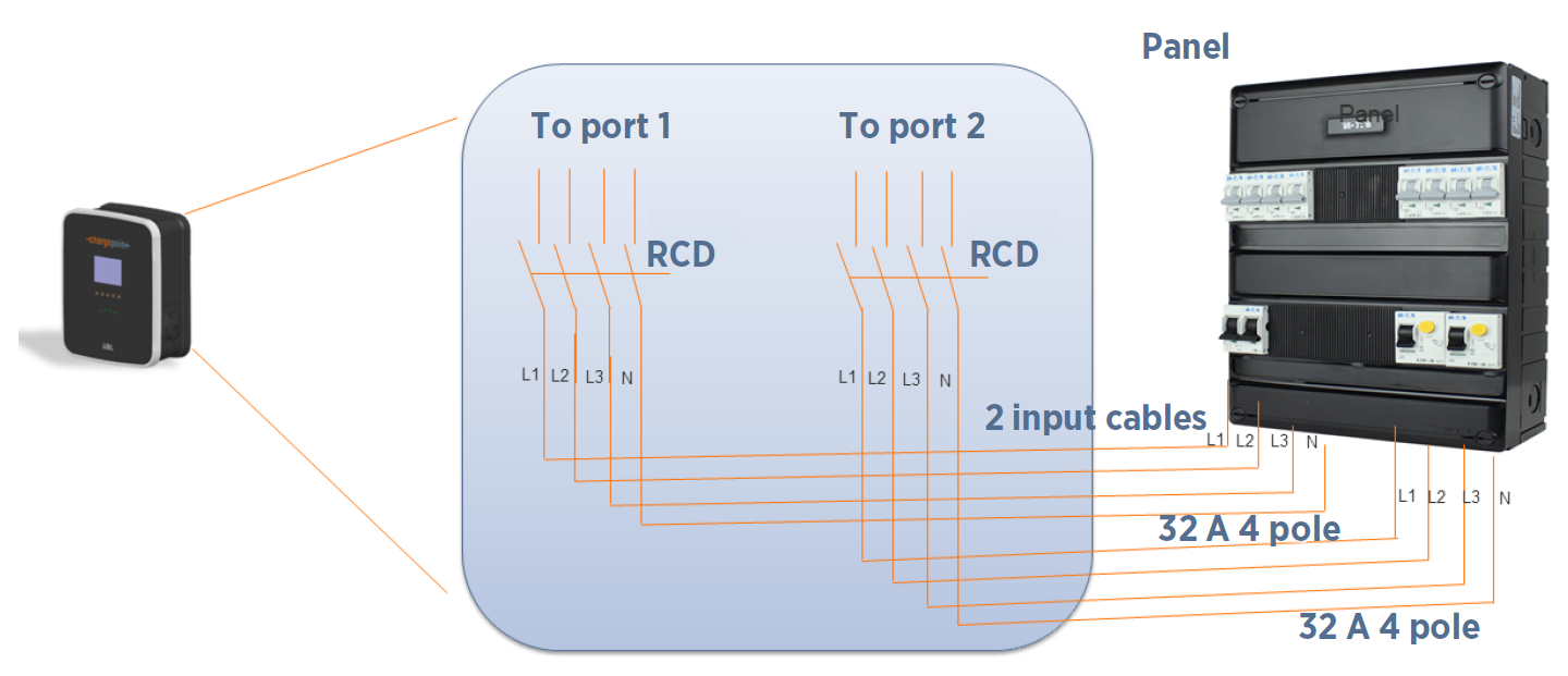
Single Phase Wiring

**RCBO![]() Residual Current Breaker with Overload Protection: Residual-Current Circuit Breaker with Overcurrent Protection
Residual Current Breaker with Overload Protection: Residual-Current Circuit Breaker with Overcurrent Protection
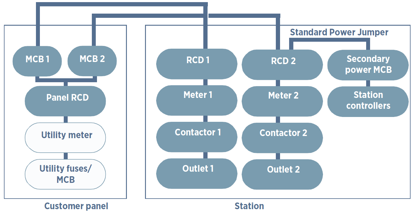
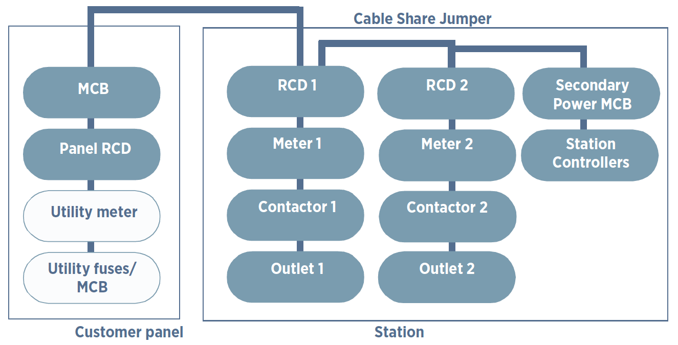
Standard Wiring, Dual Port Station
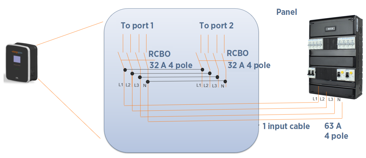
Circuit-Sharing Wiring (Dual Port Station Only)
To power a dual-port station using a single power cable, use the Cable Share Jumper. The L1 to L1 Cable Share Jumper is included with the CP4000. The L1 to L2 Cable Share Jumper is an alternative and is sold separately. Circuit sharing is available only for dual-port station configurations.
|
Output per Port |
Input Circuits |
Panel Breaker Required |
Breakers Required |
|---|---|---|---|
|
22 kW |
1 |
3-phase 63 A x 1 |
1 |
|
11 kW |
1 |
3-phase 32 A x 1 |
1 |
|
7.4 kW |
1 |
1-phase 63 A x 1 |
1 |
|
3.7 kW |
1 |
1-phase 32 A x 1 |
1 |
Meeting Power Supply Requirements
The charging station is designed for connection to and operation on rated voltages of 230 V (phase-neutral) or 400 V (phase-phase) at 50 Hz.
-
Comply to all regulatory requirements for low voltage installations according to IEC 60364-1 and IEC 60364-5-52.
-
Always connect the device to the protective earth conductor of the power source.
-
Reserve a power source exclusively for the charging station and ensure that it complies with HD 60364-7-722:2012.
-
Protect the charging station branch circuit in the panel (mains) with a suitable miniature circuit breaker (MCB
 Miniature Circuit Breaker).
Consult your electricity grid operator regarding requirements for local regulations. Depending on the desired rated power, the installation of the charging station may require registration with and/ or approval by your electricity grid operator.
Grounding Requirements
The CP4000 must be connected to a grounded, metal, permanent wiring system. An equipment-grounding conductor must be run with circuit conductors and connected to an equipment-grounding terminal on the CP4000.
A grounding conductor that complies with applicable codes must be grounded to earth at the service equipment or, when supplied by a separate system, at the supply transformer, or may be grounded to an earth electrode. Ensure the grounding conductor complies with all applicable codes.
Cellular Connectivity
Cellular connectivity is required for all CP4000 installations. The CP4000 includes a 3G cellular modem (with 2G backup) for wide area networking. It supports these bands:
-
UMTS/HSPA/3G/WCDMA Band: 800/850/900/1900/2100 MHz
-
2G/GSM/GPRS Band: 850/900/1800/1900 MHz
The charging station should be located where cellular signal levels are optimal for 3G. A consistently strong cellular signal is needed before station owners can activate the station.
Do not rely on cell phone applications to measure cellular signals when conducting site surveys. Use a cellular signal detection device (such as an Snyper-LTE![]() Long Term Evolution+ Spectrum (EU) by Siretta) to take signal strength readings at the exact proposed charging station location. Take cellular readings at the exact location of each proposed charging station location. Ensure the RSSI is -85 dBm or better, with -70 dBm or better preferred.
Long Term Evolution+ Spectrum (EU) by Siretta) to take signal strength readings at the exact proposed charging station location. Take cellular readings at the exact location of each proposed charging station location. Ensure the RSSI is -85 dBm or better, with -70 dBm or better preferred.
For reference, RSSI Signal Strength ratings are shown here:
|
RSSI |
Signal Strength |
|---|---|
|
Greater than -70 dBm |
Excellent |
|
-70 dBm to -85 dBm |
Acceptable |
|
-86 dBm to -113 dBm |
Contact cell provider for repeater installation |
If the signal strength is closer to -85 dBm, verify that the ECIO value is -10 or better.
If the RSSI signal is below -85 dBm, ChargePoint recommends contacting your telecommunication company to request a cellular repeater. If you have a provider for company cell phones, consult them first. A 3G (or 4G that is backwards compatible to 3G and 2G) repeater can improve the cellular signal for the charging stations as well as for employees and customers that are on that network in the area.
Consult your ChargePoint account manager for additional guidance. ChargePoint O&M partners can validate acceptable cellular signal strength at the site using a cellular strength reader.
