Install Bracket and CMK
Before proceeding with installation, follow the applicable CMK![]() Cable Management Kit or non-CMK
Cable Management Kit or non-CMK![]() Cable Management Kit preparation step below.
Cable Management Kit preparation step below.
Preparation (Stations without CMK)
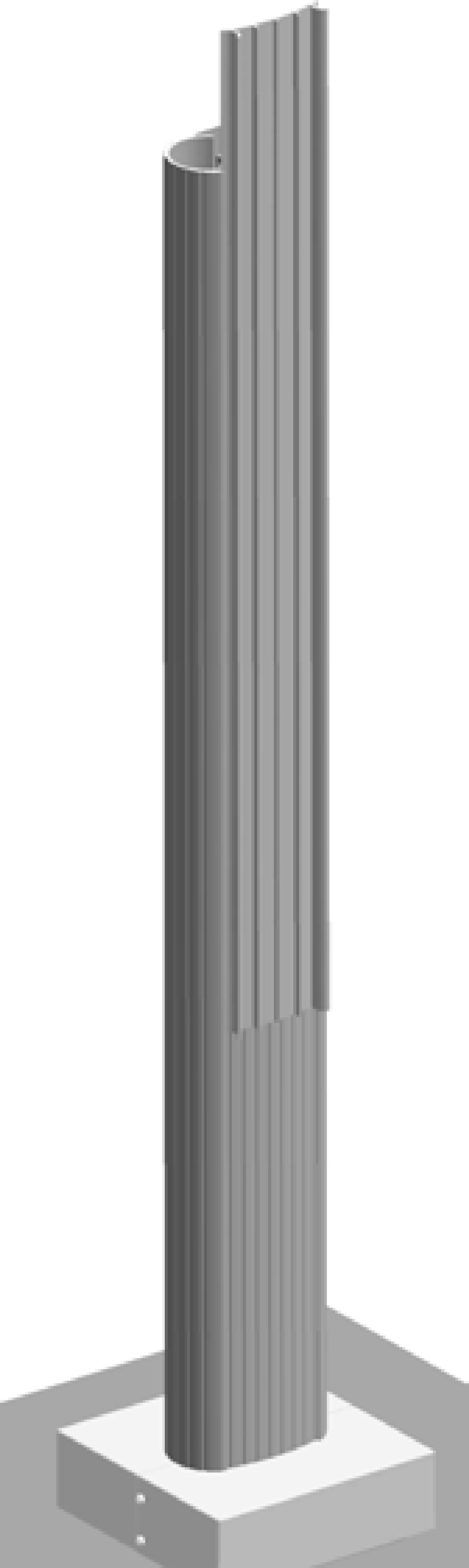
Slide the spacer at the back of the pedestal upward to remove. Discard the spacer (this spacer is only required if you are installing a CMK![]() Cable Management Kit).
Cable Management Kit).
Prepare the CMK for Mounting
-
Position the Cable Management Kit (CMK
 Cable Management Kit) packaging so that the bottom of the CMK Cable Management Kit is near the base of the pedestal.Do not unwrap the ropes.
 -
Remove and discard the two shipping screws (a).
When you remove the shipping screws, the counterweights are free to move in either direction. To prevent damage or injury, always carry the assembly with the top end higher than the bottom end. -
Remove the foam packaging.
If you are replacing the EV Electric Vehicle PARKING signage with your own custom signage, it is easier to do it now. Refer to the replacement guide for signs available at ChargePoint Product Reference Documentation.
Single Station (No CMK)
-
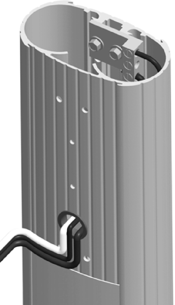
Remove the ground lug using an 11 mm (7/16 in) wrench.
Save the 1/4 in x 20 screws to reinstall in a later step.
-
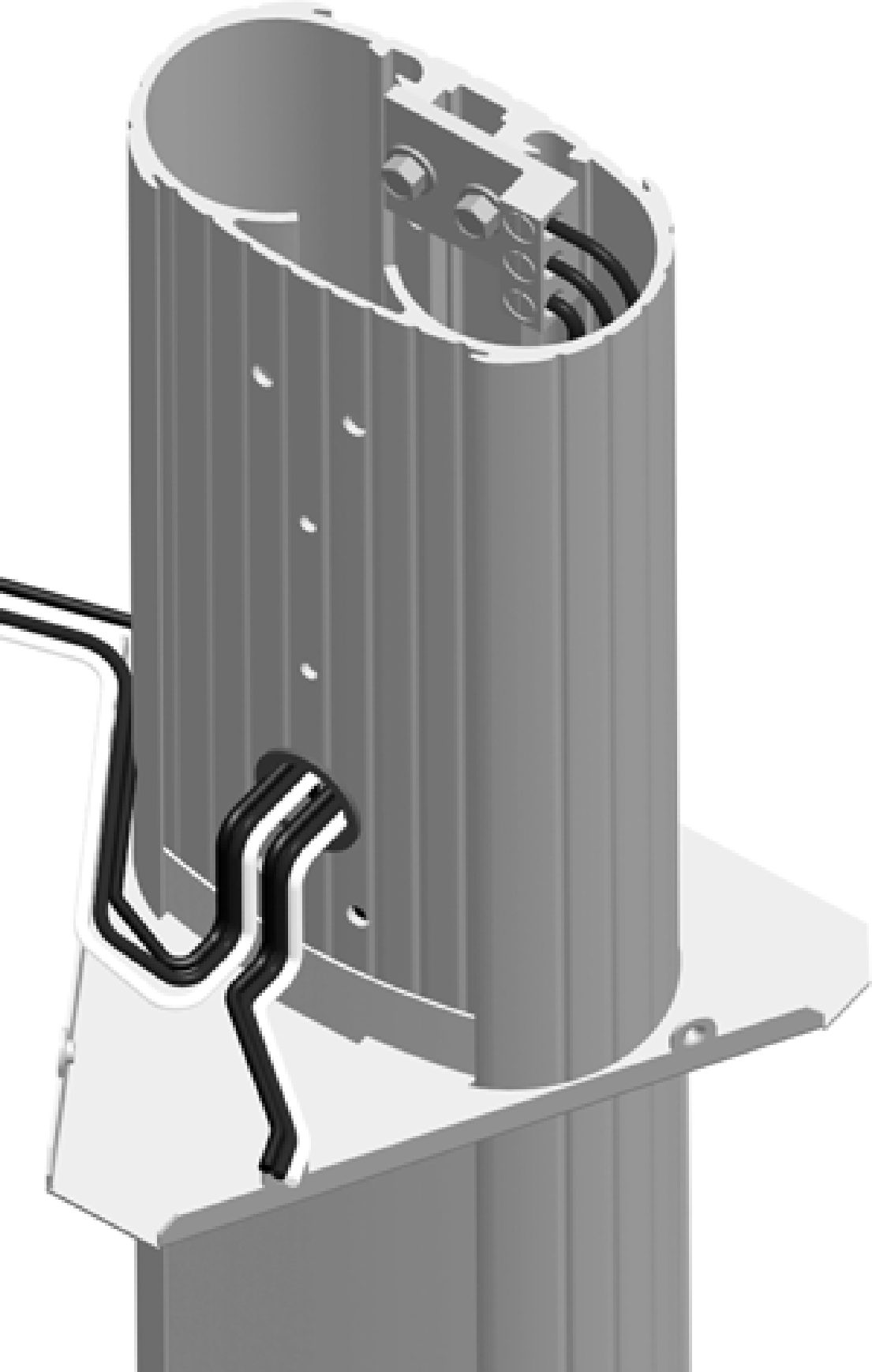
Connect the ground wire from the service wiring to the ground lug.
-
Run a 6 mm2 (10 AWG
American Wire Gauge) ground wire from the ground lug through the wiring opening in the front of the pedestal. -
Reinstall the ground lug to the pedestal using the 11 mm (7/16 in) wrench and the two 1/4 in x 20 screws you removed.
-
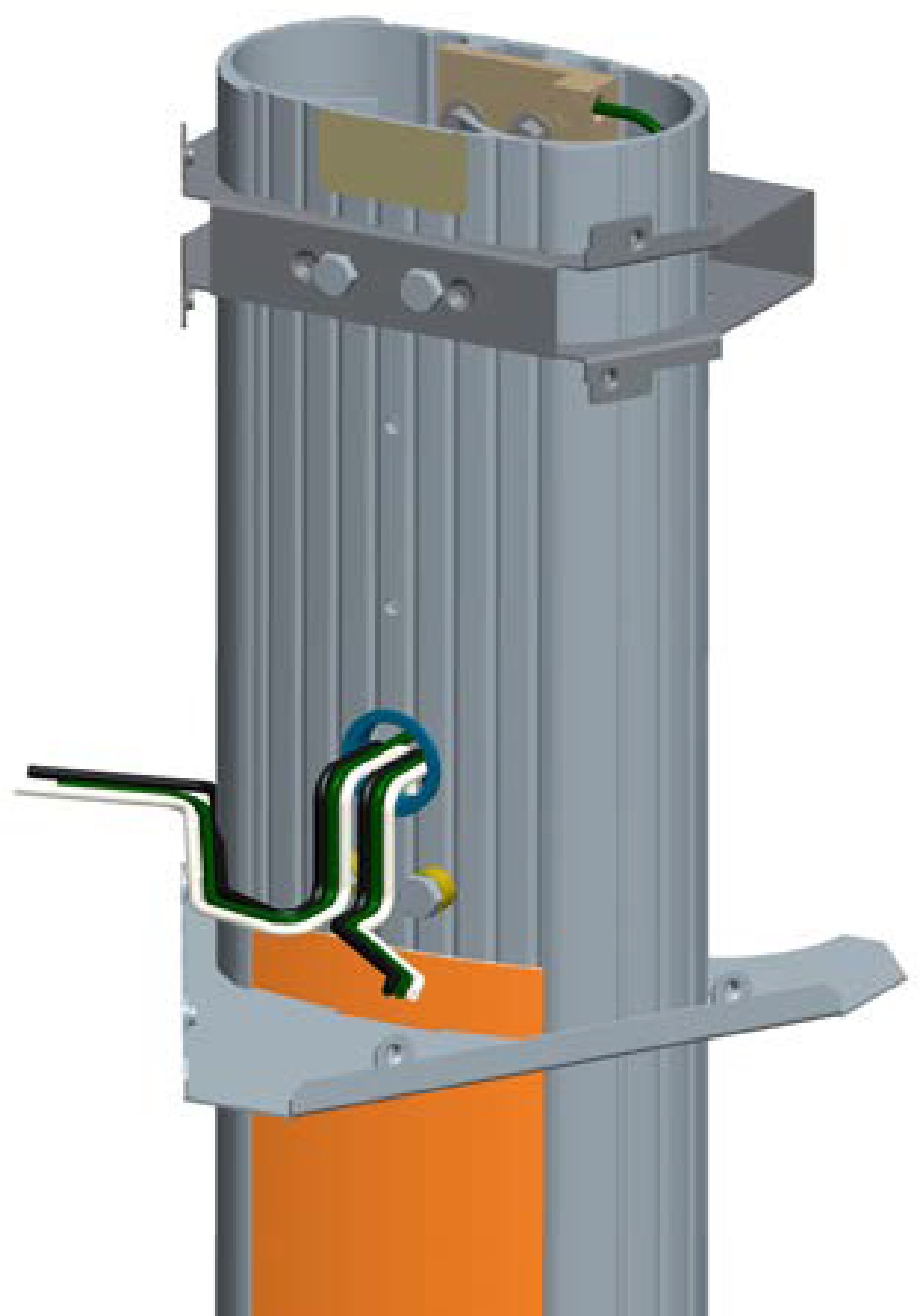
Run the remaining service wiring through the opening in the front of the pedestal.
-
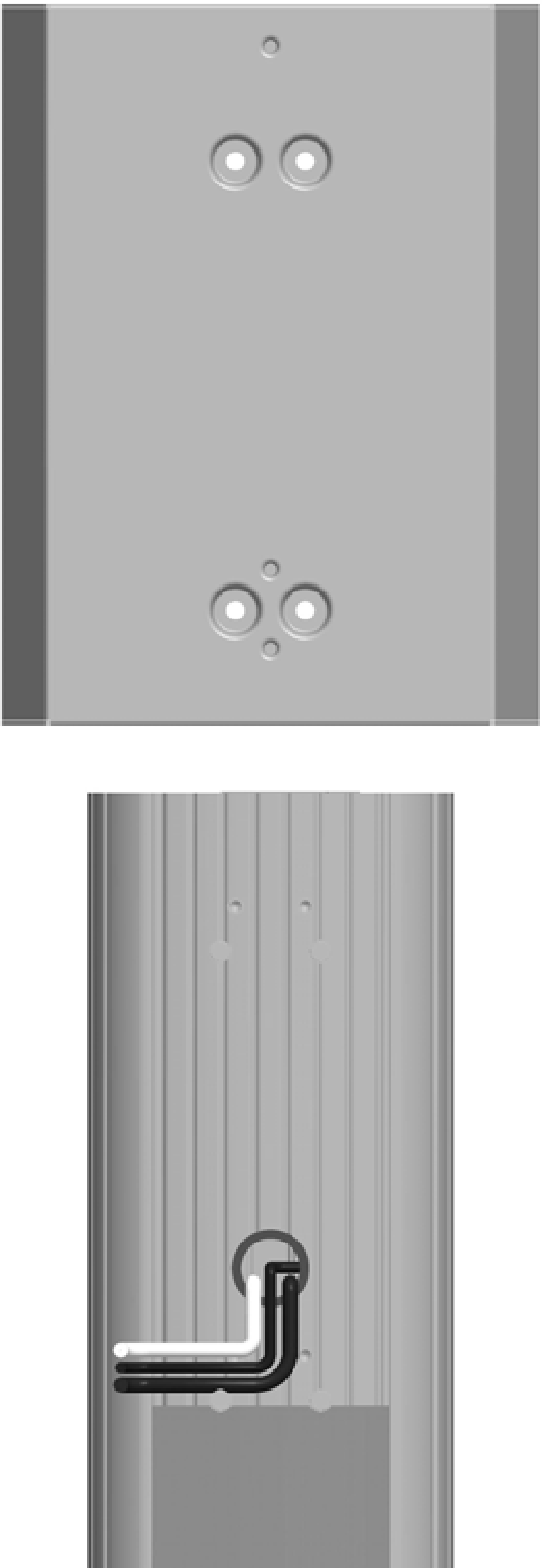
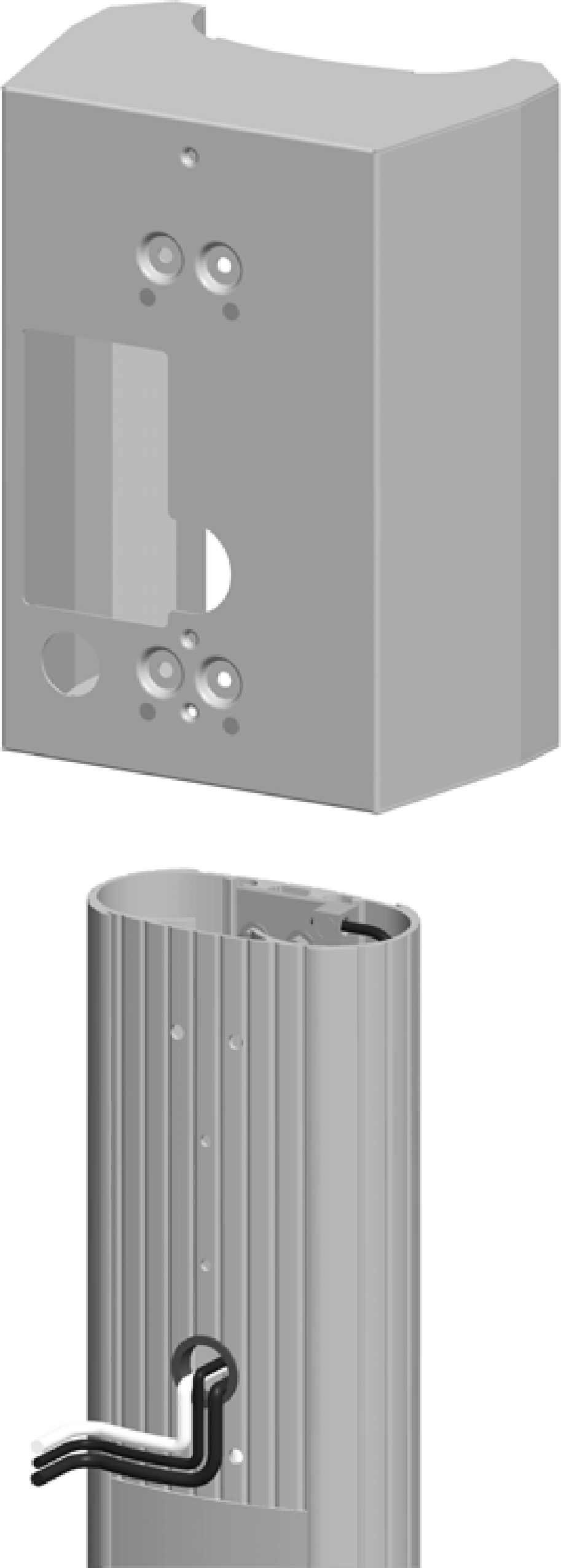
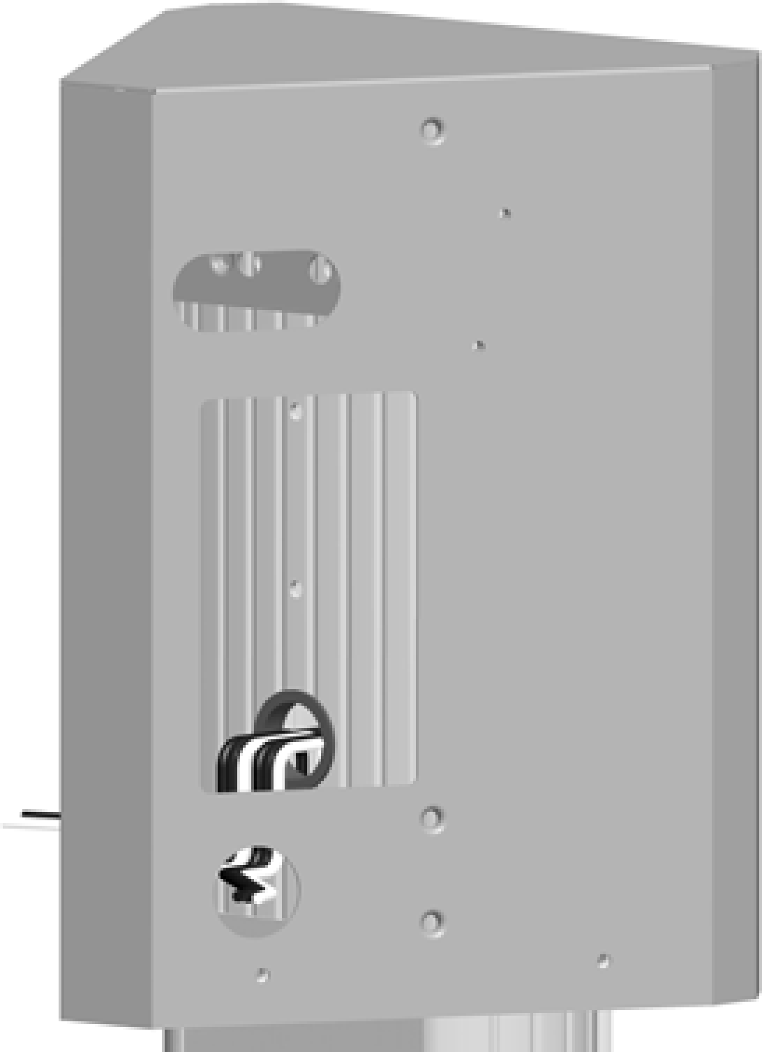
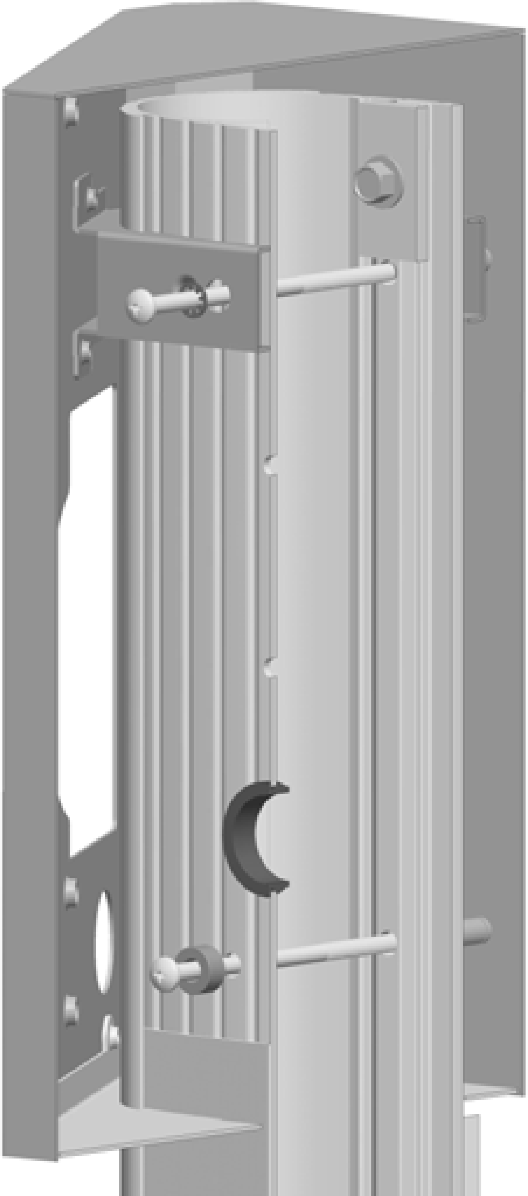
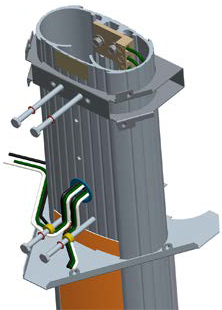
Slide the bracket over the pedestal. The two holes at the top and two holes at the bottom of the bracket must align with the corresponding holes in the pedestal.
The bracket must slide over the service wiring. Lay the wiring as flat as possible to protect the wires from damage. -
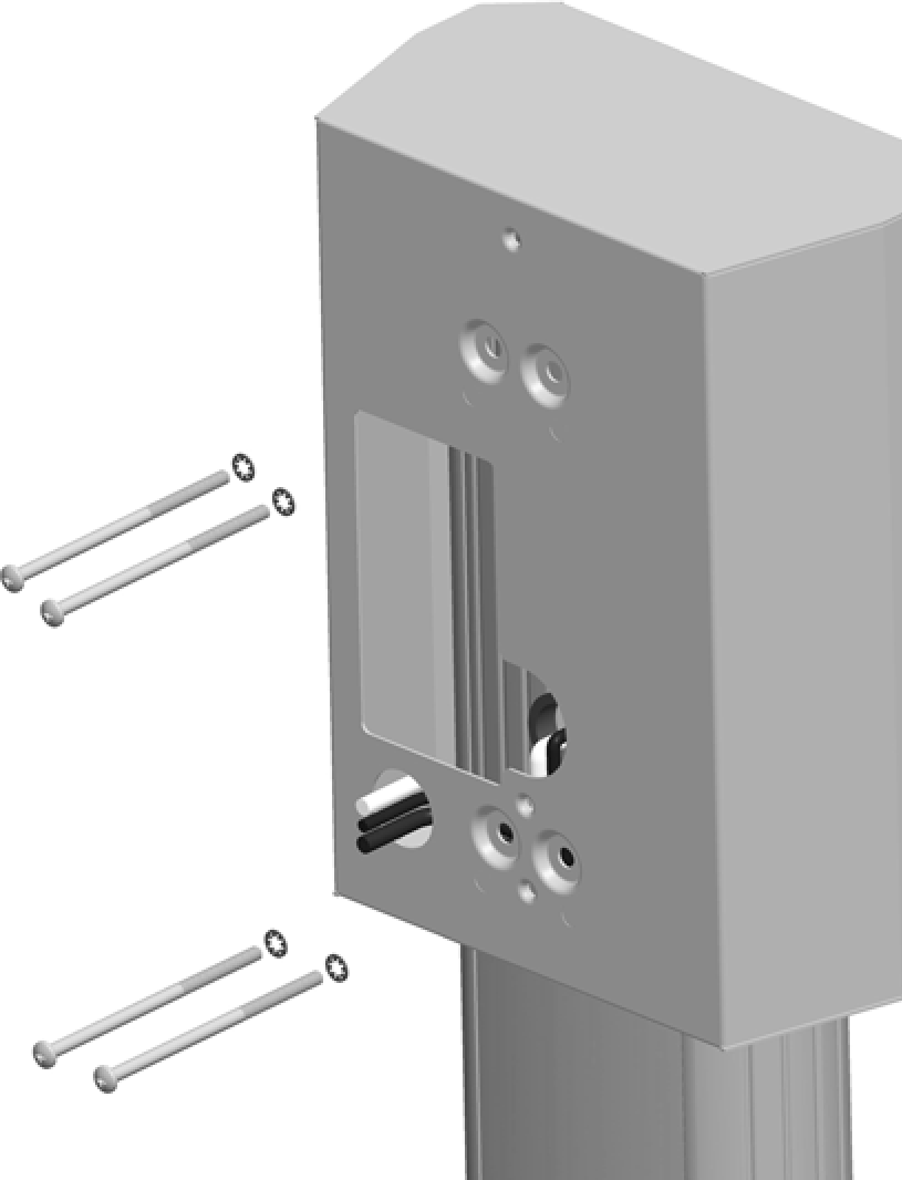
Fasten the bracket to the pedestal by inserting the four 10/32 x 4 in screws and four #10 lock washers through the bracket and into the stand-offs on the pedestal. Tighten using a Phillips screwdriver.
-
Route the service wiring through the wiring hole in the front of the bracket.
You have now completed installation of the bracket and are ready to install the station and charging cord.
Single Station with CMK
-
Remove the ground lug by removing its two screws using a 9 mm (3/8 in) socket wrench. Save the screws to reinstall in a later step.
-
Connect the ground wire from the service wiring to the ground lug.
-
Run a 6 mm2 (10 AWG
American Wire Gauge) ground wire from the ground lug through the wiring opening in the front of the pedestal. -
Reinstall the ground lug to the pedestal using the 9 mm (3/8 in) wrench and the two screws you removed.
-
Route the remaining service wiring through the opening in the front of the pedestal.
-
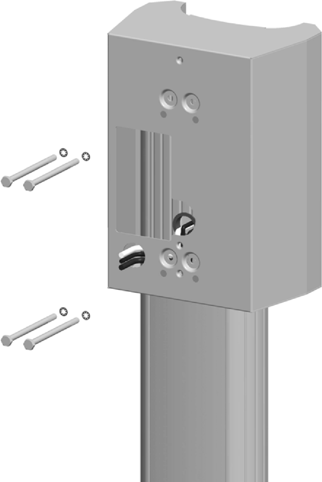
Slide the bracket over the pedestal. The two holes at the top and two holes at the bottom of the bracket must align with the corresponding holes in the pedestal.
-
Insert the four 1/4 in - 20 x 4 in hex screws and 1/4 in lock washers through the bracket and pedestal.
-
Route the service wiring through the wiring hole in the front of the bracket, as shown.
-
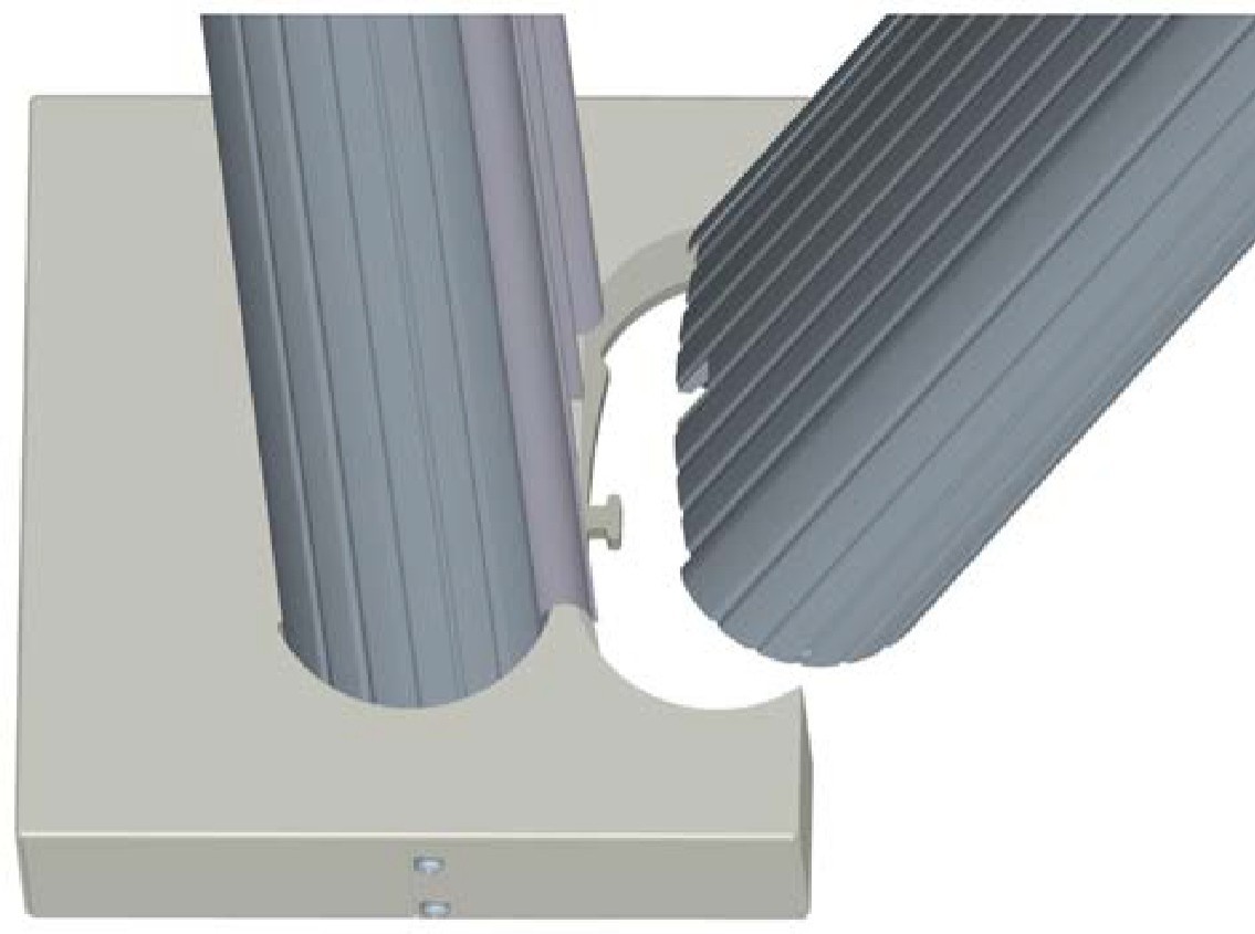
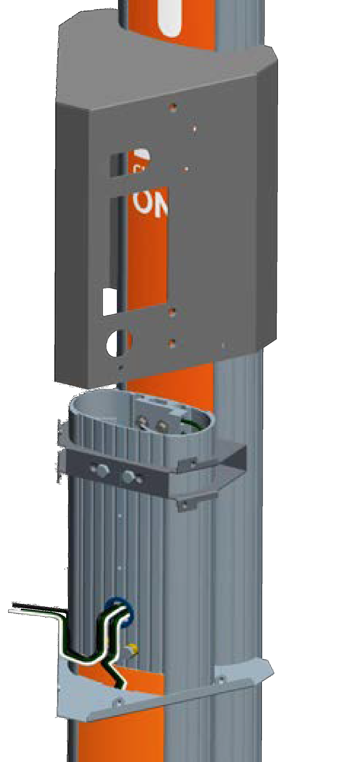
Position the slot at the bottom of the CMK
Cable Management Kit onto the screw at the bottom of the pedestal. Hold the CMK Cable Management Kit against the back of the pedestal while aligning the four screws (inserted in the previous step) into the corresponding holes in the CMK Cable Management Kit.The spacer on the pedestal should slide into the ridges on the CMK Cable Management Kit. -
While holding the bracket and CMK
Cable Management Kit in place, tighten the four screws into the CMK Cable Management Kit using the 11 mm (7/16 in) socket.
You have now completed installation of the bracket and CMK![]() Cable Management Kit and are ready to install the station and charging cord.
Cable Management Kit and are ready to install the station and charging cord.
Dual Station (no CMK)
-
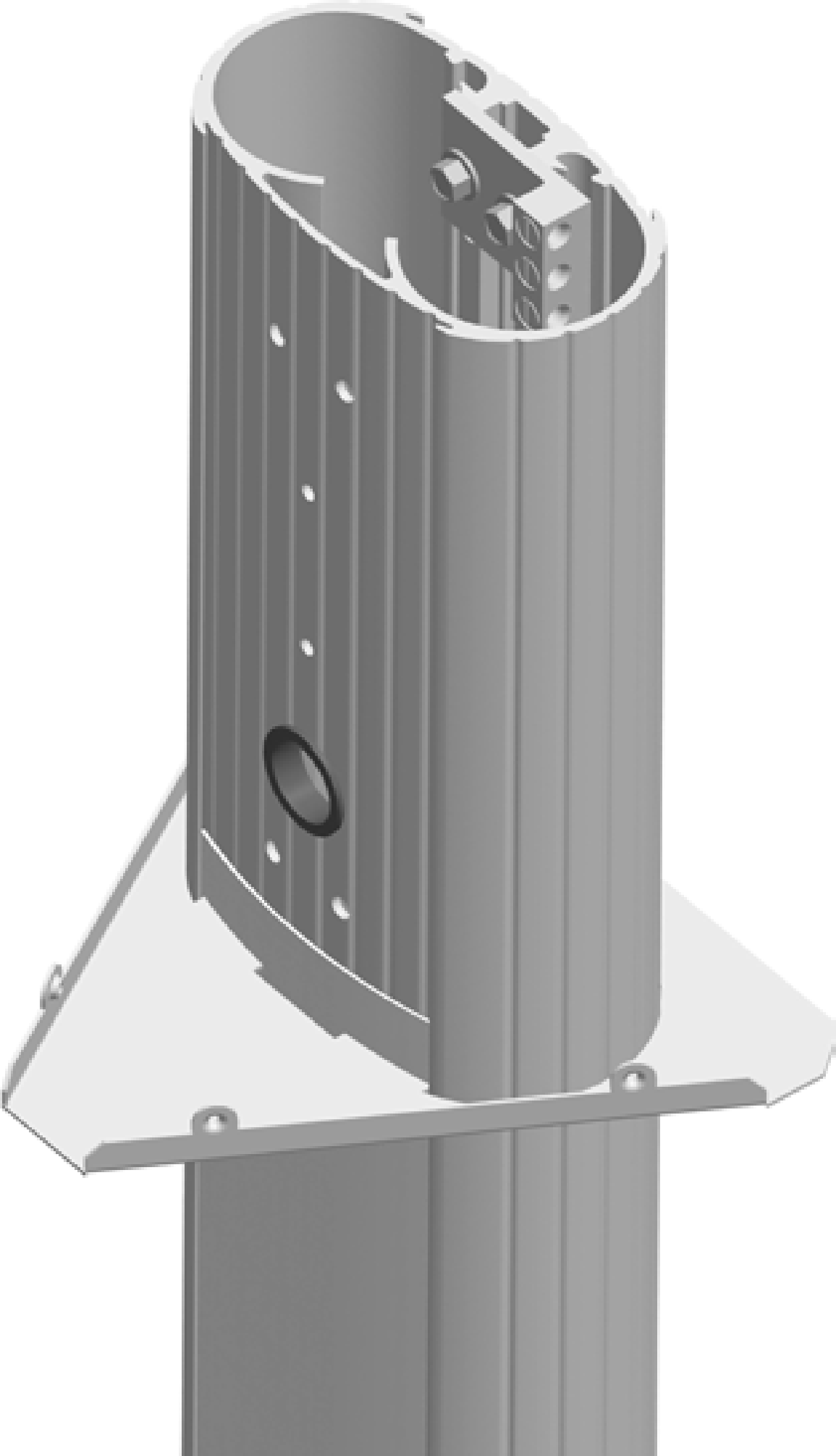
Slide the bottom bracket brace over the pedestal, allowing it to drop to the bottom.
-
Remove the ground lug using a 11 mm (7/16 in) wrench. Save the 1/4 in x 20 screws to reinstall in a later step.
-
Connect the ground wire from the service wiring to the ground lug.
-
Run two 6 mm2 (10 AWG
American Wire Gauge) ground wires from the ground lug through the wiring opening in the front of the pedestal. -
Reinstall the ground lug to the pedestal using the 11 mm (7/16 in) wrench and the two 1/4 x 20 screws you removed.
-
Route the remaining service wiring through the opening in the front of the pedestal.
STOP! If you are installing the Power Share kit, follow the steps in Appendix C before continuing with the next step. -
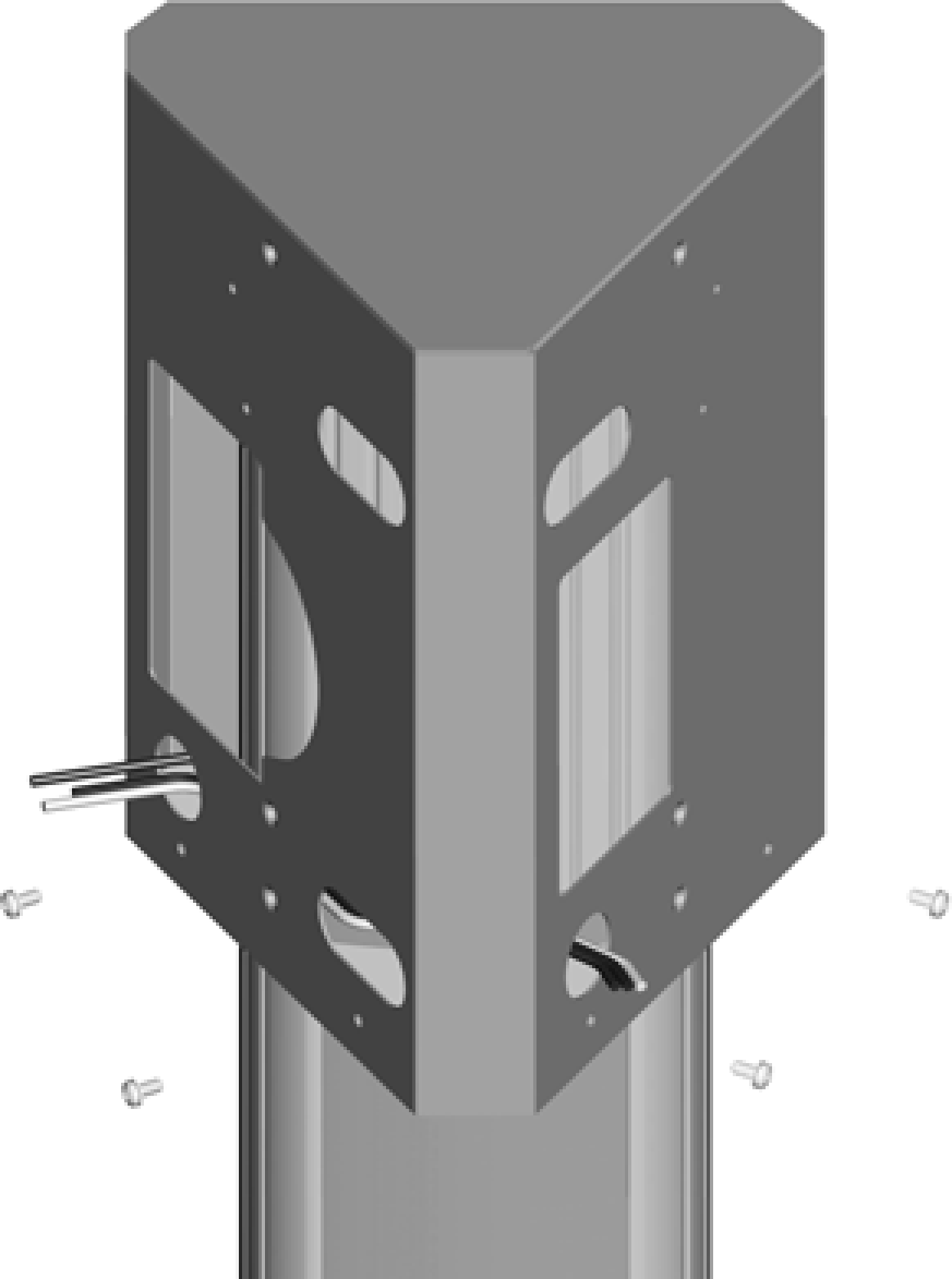
Slide the main bracket over the pedestal, aligning the holes in the main bracket with the corresponding holes in the pedestal.
-
Fasten the main bracket to the pedestal using two 10-32 x 4 in screws and lock washers at the top and two 10-32 x 4 in screws and spacers at the bottom.
-
Route the service wiring through the wiring hole on each left corner of the main bracket fronts.
-
Slide the bottom brace up, aligning its holes with the main bracket. Fasten it to the main bracket using four #8 - 32 x 3/8 in screws, two on each side.
You have now completed installation of the bracket and are ready to install the station and charging cord.
Dual Station with CMK
-
Slide the bottom bracket brace over the pedestal, allowing it to drop to the bottom.


-
Remove the ground lug using a 11 mm (7/16 in) wrench. Save the two 1/4 in x 20 screws to reinstall in a later step.
-
Connect the ground wire from the service wiring to the ground lug.
-
Run two 6 mm2 (10 AWG
American Wire Gauge) ground wires from the ground lug through the wiring opening in the front of the pedestal. -
Reinstall the ground lug to the pedestal using the 11 mm (7/16 in) wrench and the two 1/4 in x 20 screws you removed.
-
Route the remaining service wiring through the opening in the front of the pedestal.
STOP! If you are installing the Power Share kit, follow the steps in Appendix C before continuing. -
Install lock washers on each of the four 101 mm (4 in) long 1/4 in x 20 screws, and install spacers on the two lower screws. Insert all four screws.
-
Position the slot at the bottom of the CMK
Cable Management Kit onto the alignment tab at the bottom of the pedestal. Hold the CMK Cable Management Kit against the back of the pedestal while aligning the four screws (inserted in the previous step) into the corresponding holes in the CMK Cable Management Kit.The spacer on the pedestal should slide into the ridges on the CMK
Cable Management Kit. -
While holding the bracket and the CMK
Cable Management Kit in place, tighten the four screws into the CMK Cable Management Kit using the 11 mm (7/16 in) socket wrench. -
Slide the main bracket over the pedestal, aligning the holes in the main bracket with the corresponding holes in the top internal brace.
-
Route the service wiring through the wiring hole on each left front corner of the main bracket fronts.
-
Fasten the main bracket to the pedestal by installing four 8-32 x 3/8 in screws into the internal bracket.
-
Slide the bottom brace up, aligning its holes with the main bracket. Fasten it to the main bracket using two 8-32 x 3/8 in screws on each side.
You have now completed installation of the bracket and CMK![]() Cable Management Kit and are ready to install the station and charging cord.
Cable Management Kit and are ready to install the station and charging cord.
