Introduction
Before performing any procedure, the technician must disconnect the power to the charging station at the service panel. Follow local code to de-energize the applicable circuit and lockout/tagout the upstream breaker before proceeding. Use a multimeter and check that the power is off. Keep power off for the circuit until all cover panels are correctly reinstalled and the work is complete.
FAILURE TO FOLLOW THESE INSTRUCTIONS CAN RESULT IN SERIOUS INJURY, LOSS OF LIFE, OR PROPERTY DAMAGE.
Site Prerequisites
Ensure that the location of the installation site is appropriate and you are ready to install the CPF32:
-
The CPF32 must be located within 38 m (125 ft) line-of-sight from a CPGW
 ChargePoint Gateway (ChargePoint Gateway).
 -
Ensure the appropriate wiring, circuit protection, and metering is in place at the installation location by reviewing the wiring diagrams and grounding requirements described in Grounding and Wiring. All wiring is installer-provided except as noted in the manual. Ensure that wire type and color follows local and regional code.
-
Follow the instructions and Prepare the installation site. The mounting template for the pedestal is included with the Pedestal Kit, and a PDF version is available at ChargePoint Product Reference Documentation. Ensure the PDF version is accurate by printing it at 100% scale on 11x17 inch paper and verifying at least one dimension.
Required Tools
-
Ratchet and 10 mm (3/8 in) and 11 mm (7/16 in) sockets
-
12 mm (1/2 in) drive torque wrench, rated to at least 136 Nm (100 ft-lbs)
-
24 mm (15/16 in) 6-point deep socket, for 16 mm (5/8 in) nut
-
Adjustable wrench
-
Bubble level
-
#2 Phillips screwdriver
-
Wire stripper
-
Voltage tester
-
T10 Torx driver
UK installations only:
-
Cable gland: 17 mm - 27 mm cable diameter
-
Grounding cable: 6 mm2 (10 AWG
American Wire Gauge), Stranded,300 V -
Terminal Ring Lug: 6 mm2 (10 AWG
American Wire Gauge), non-insulated, M8 -
Terminal Ring Lug: 6 mm2 (10 AWG
American Wire Gauge), non-insulated, No. 6 -
M8 x 8mm button head cap screw
-
M8 external tooth washer
-
M8 nut
Overview of Steps
Check Shipping Boxes for Correct Contents
Main Unit
Each main charging unit (one or two, depending on whether you ordered a single or dual station model) ships in a box containing:
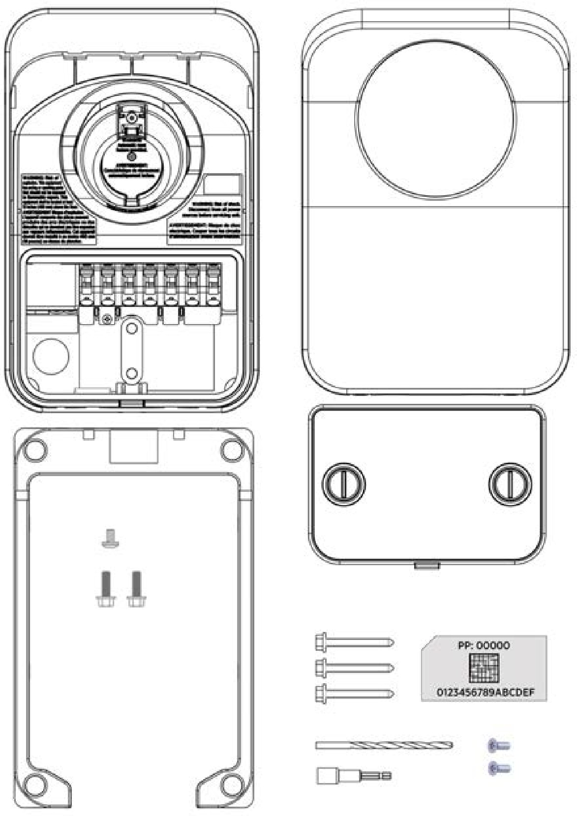
-
Station (1)
-
Cover (1)
-
Mounting skirt(1)
-
Wire cover (1)
-
5 mm (3/16 in) drill bit (1)*
-
6 mm (1/4 in) X 51 mm (2 in) lag screws (3)*
-
Driver bit (1)
-
6 mm (1/4 in)-20 x 19 mm (3/4 in) hex bolts (2)
-
6 mm (1/4 in)-20 x 9 mm (3/8 in) Phillips screw (1)
-
T10 Torx screws (2)
-
Spare Activation Label (1). A duplicate label is attached to the inside of the main unit. KEEP this spare label because it contains important information that is needed to activate the station on the ChargePoint network.
*Not used in pedestal mount installations. These can be discarded.
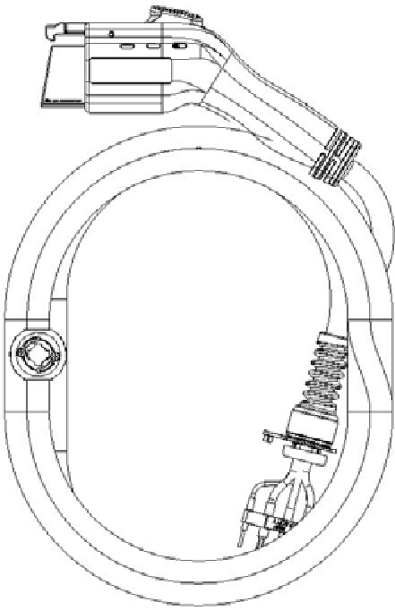
Charging Cord
Each charging cord (one or two, depending on whether you ordered a single or dual station model) ships in a separate box. If you ordered the Cord Management Kit (CMK![]() Cable Management Kit), each cord includes an integrated clamp.
Cable Management Kit), each cord includes an integrated clamp.
Pedestal
-
Main body
-
Pedestal covers (3)*
-
Pedestal CMK
Cable Management Kit spacer (attached) -
8-32 X 9 mm (3/8 in) screws (4)
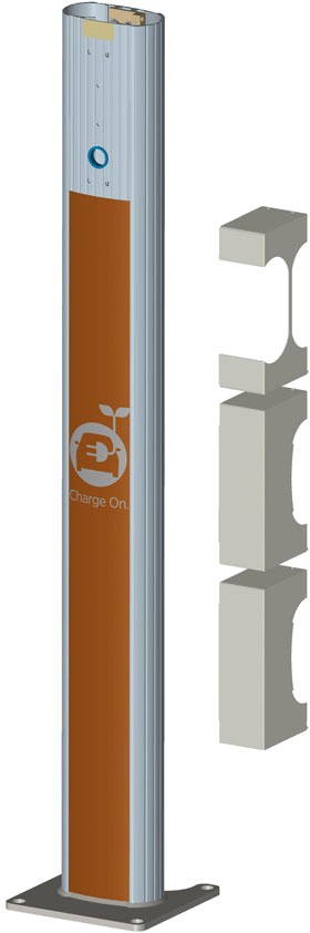
*The three pedestal cover types are front (a), back without CMK
Cable Management Kit (b), and back with CMK Cable Management Kit (c). Whicheverback cover is not used can be discarded.
Note: To prepare the installation site for installing a pedestal mount, you also need the contents of the Pedestal Mount Kit, which ships separately (see Prepare the installation site).
Bracket Kit
The contents of the bracket kit vary depending on the specific model ordered.
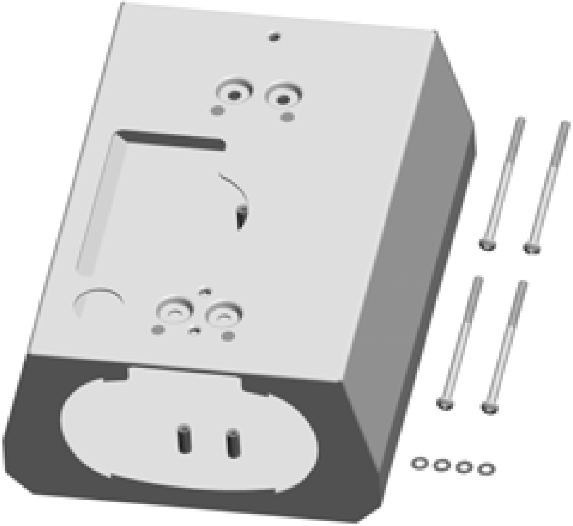
Single Station (no CMK)
-
Bracket
-
10-32 x 102 mm (4 in) screws (4)
-
Lock washers (4)
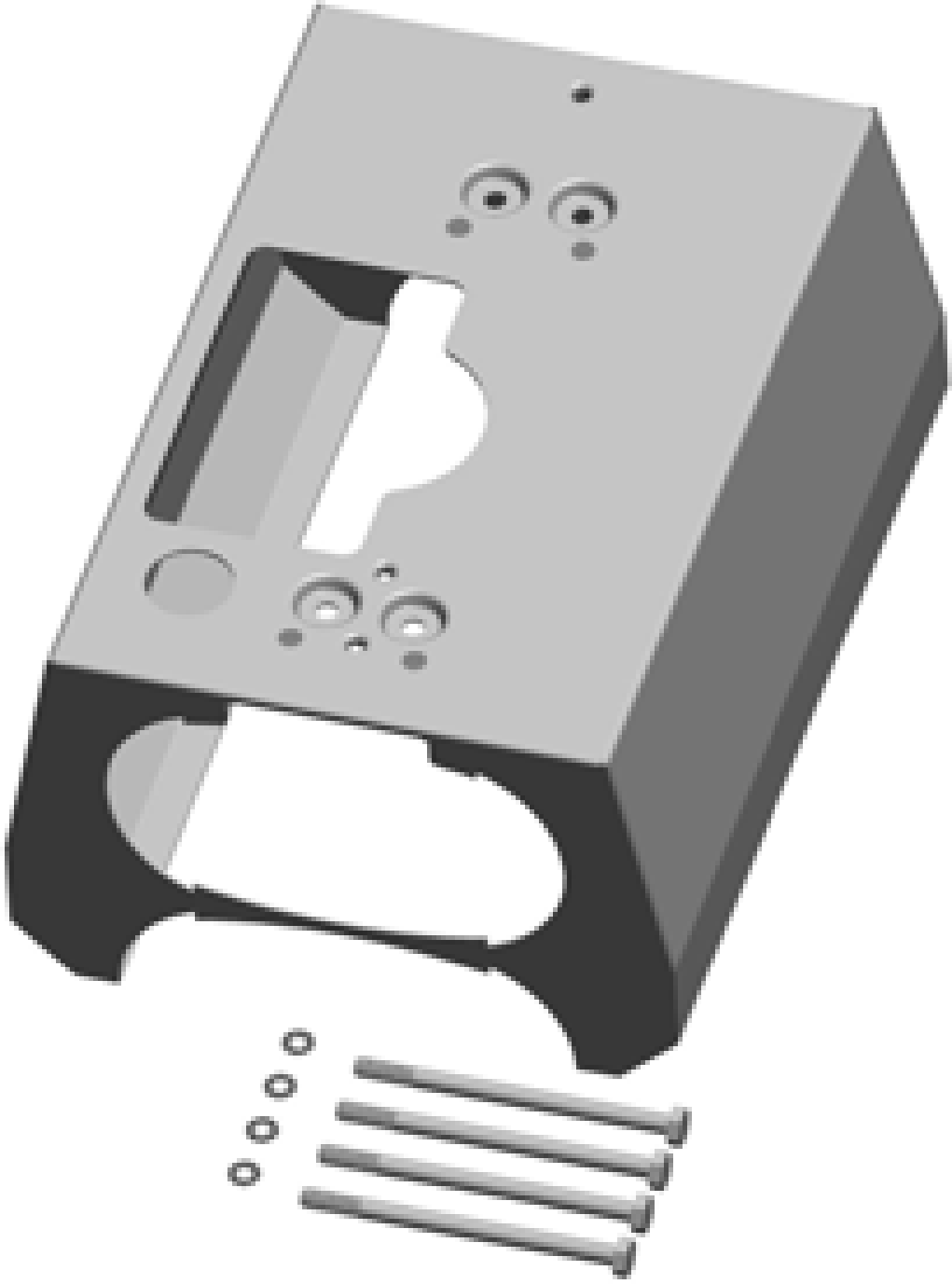
Single Station with CMK
-
Bracket
-
6 mm (1/4 in) - 20 x 102 mm (4 in)
screws (4)
-
Lock washers (4)
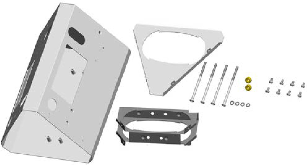
Dual Station (no CMK)
-
Main bracket
-
Bottom bracket cover
-
Internal bracket
-
10-32 x 102 mm (4 in) screws (4)
-
#8 - 32 x 9 mm (3/8 in) screws (8)
-
Nylon spacers (2)
-
Lock washers (4)
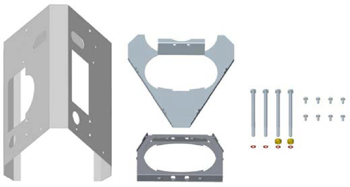
Dual Station with CMK
-
Main bracket
-
Top internal brace
-
Bottom internal brace
-
6 mm (1/4 in) - 20 x 102 mm (4 in)
screws (4)
-
#8 - 32 x 9 mm (3/8 in) screws (8)
-
Spacers (2)
-
Lock washers (4)
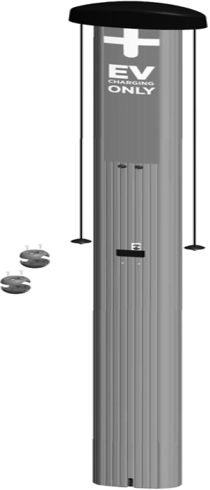
Cord Management Kit (CMK)
If you ordered the optional cord management kit, it ships in a box containing:
-
Cord management assembly with pre-installed “EV
Electric Vehicle CHARGING ONLY” sign (1) -
Cable clamps (2 extra sets)