Install the Pedestal
Proceed with the topics provided below to install the pedestal.
Mount and Level the Pedestal
-
Pull service wiring up through the mounting surface, leaving approximately 1.8 m (6 ft) extending above grade.
-
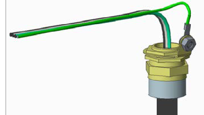
UK only:
-
Fasten an installer-supplied 17 mm - 27 mm cable diameter cable gland to the end of the service wiring.
-
Attach a non-insulated M8 terminal lug to a 6
mm2 (10 AWG
 American Wire Gauge) 300 V stranded green/yellow ground wire.
 -
Use a 5 mm (3/16 in) driver to connect the ground wire to the gland with a M8 x 8mm x 1.25 button head cap screw, M8 external tooth washer, and M8 nut.
-
-
Remove the top nut and top washer from each of the four bolts in the pad.
-
Place the pedestal over the conduit, routing the service wiring through the column. Ensure the long curved edge of the base plate (which is the cut-out for a CMK
Cable Management Kit) is located at the back of the station.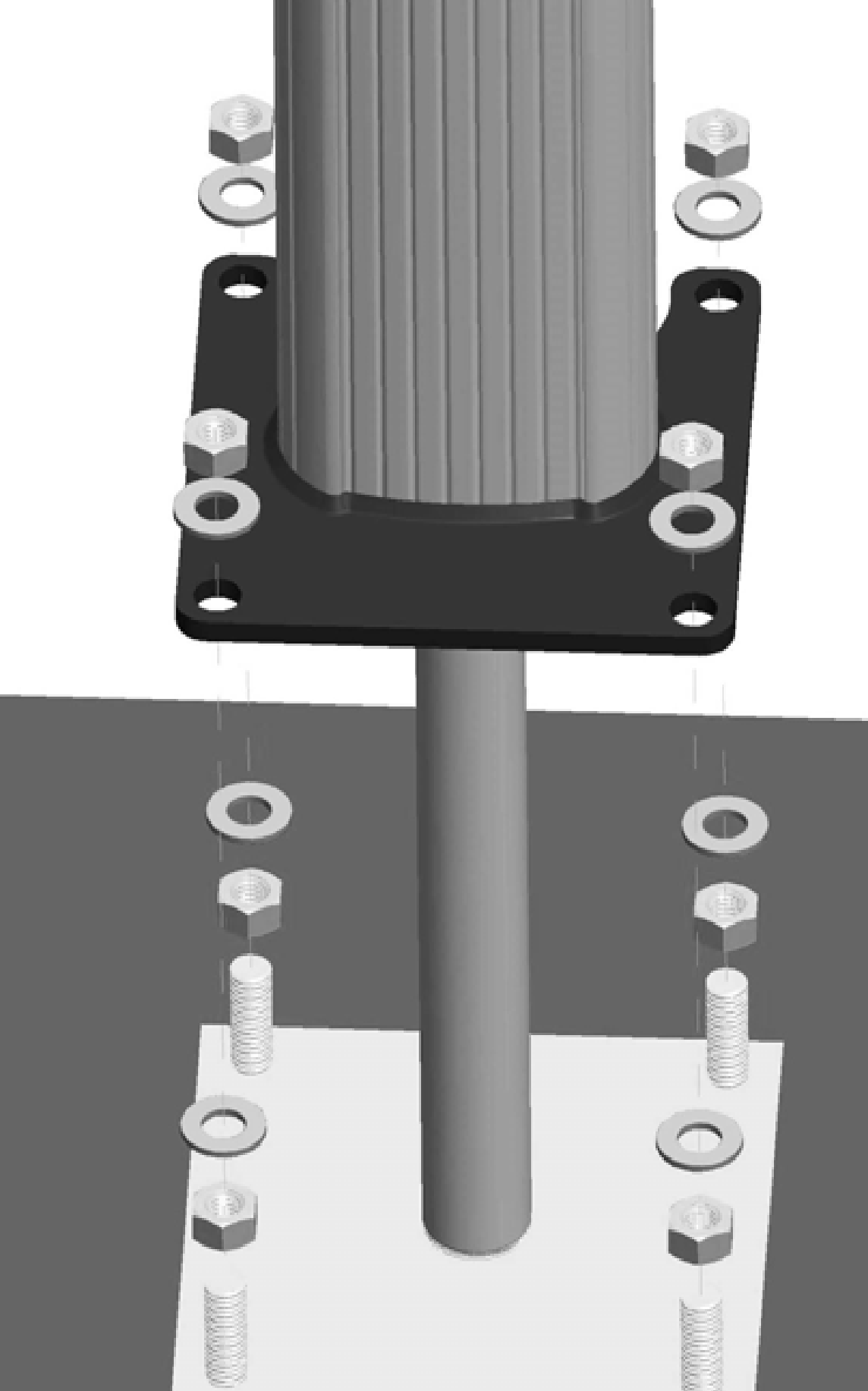
-
Adjust the lower nuts as necessary to ensure the pedestal is level.
-
When level, fasten the pedestal to the bolts using the 16 mm (5/8 in) nuts and washers and the 12 mm (1/2 in) drive torque wrench with 124 mm (15/16 in) deep socket, as shown. Torque the top nuts to 122 Nm (90 ft-lbs).
Install Pedestal Covers
-
Position the two-piece pedestal covers over the bottom of the pedestal, as shown:
-
If the station is not using a CMK
Cable Management Kit, use the back pedestal cover without the indentation. -
If the station is using a CMK
Cable Management Kit, use the back pedestal cover with the indentation.
-
Insert the four 8-32 x 9 mm (3/8 in) screws, two into each side of the pedestal, as shown.
-
Tighten the screws using a Phillips screwdriver.
-
Discard the extra cover.

