Install Station and Charging Cord
Proceed to the following topics to install the charging station and charging cord.
Mount the Station(s)
Follow these steps for each station:
-
Insert a 6 mm (1/4 in) - 20 x 9 mm (3/8 in) screw (a) into the top center hole on the front bracket using a #2 Phillips screwdriver. Leave the screw protruding approximately 6 mm (1/4 in) to create a 3 mm (1/8 in) gap between the back of the screw head and the bracket.
-
Position the mounting skirt (b) against the back of the main unit (c) as shown.
-
Route the service wiring through the hole in the back of the main unit.
-
Hang the mounting skirt and main unit on the top protruding screw on the bracket.
-
Secure the main unit by inserting the two 6 mm (1/4 in) - 20 x 19 mm (3/4 in) hex screws (d) through the main unit (near the
bottom center) and into the bracket as shown. Tighten using a 9 mm (3/8 in) hex driver.

Connect the Service Wiring
Follow these steps for each station:
-
UK only: Use a 6 mm2 (10 AWG
 American Wire Gauge), non- insulated, No. 6 terminal ring lug and a MET screw to land the grounding wire on the ground stud behind the terminal block.
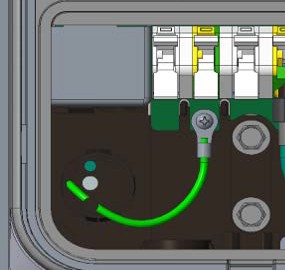
-
Ensure that the service wiring can easily reach the connectors on the charging station’s terminal block. Trim the wiring to remove excess length.
-
On each connector, press the white clip completely down until it snaps into place.
Ensure that each wire is fully inserted into the connector before pressing it into place with the white clip. -
Strip each wire 12 mm (1/2 in).
-
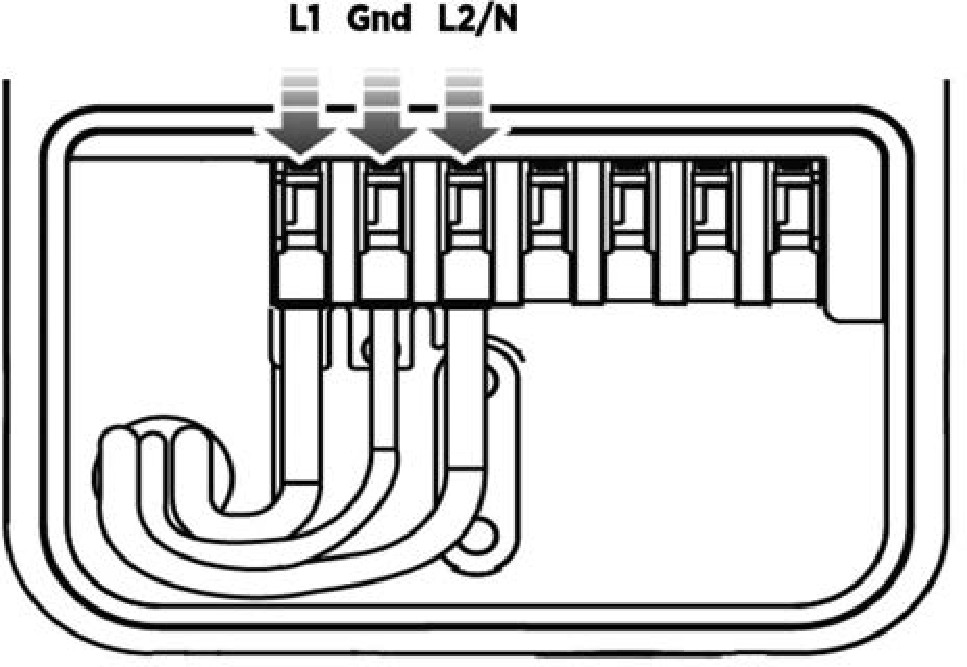
Ensure the white clips on the terminal block are open. Fully insert wires into the connectors on the left side of the terminal block, as shown.
Connect the Charging Cord(s)
Follow these steps for each charging cord:
-
Remove the cable clip connected to the wiring end of the cord, but do not discard it. Note the location of the slot, because you will re-insert the clip into the same location in a later step.

-
Insert the wire ends into the opening on the lower right side of the station, pushing up until the silver conductors are no longer visible below the enclosure.
-
Push the cord upward and slide the cable clip into the slot on the strain relief until it snaps into place.

-
Insert the wires into the corresponding connectors on the right side of the terminal block, as shown. On each connector, press the white clip all the way down until it snaps into place.

Attach the Station Cover(s)
Follow these steps for each station:
-
Place the wire cover over the exposed wiring on the terminal block.
-
Using a coin, lock the wire cover in place as shown.
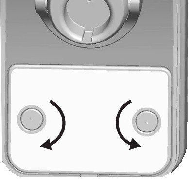 To avoid damage, do not use a screwdriver.
-
Place the cover over the front of the station.

-
Use two T10 Torx screws to fasten the front cover to the bottom of the station as shown.

Attach the Charging Cord(s) to the CMK
If your station is equipped with a cord management kit, follow these steps to connect each charging cord to the nylon rope that keeps the charging cord in place:
-
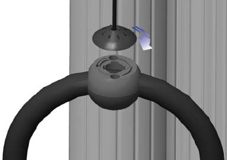
Gently extend the charging cord completely out and away from the station. Rotate the plug as needed to remove any twist or kinks.
-
Align the knot bearing on each rope to its corresponding mating feature on the cable clamp. Push down while turning the knot bearing clockwise approximately 1/4 turn.
The physical installation of the CPF32 is now complete. You are ready to prepare the station for activation on the ChargePoint network.
