Introduction
This section describes the purpose and scope of this guide and provides an overview of the ChargePoint® Express Distro Power Link 2000 .
About This Guide
This guide provides instructions for installing the pedestal-mount Power Link 2000. It covers preparation requirements, mounting and anchoring procedures, electrical and communication connections, commissioning steps, and verification tasks needed to place the station into service.
This guide is intended for licensed electricians, installation contractors, and construction professionals responsible for installing Power Link 2000 equipment in accordance with local codes and ChargePoint requirements.
Please note that Power Link 2000 is available in multiple variations and mount types, and installation procedures differ for each. This installation guide applies specifically to Variation Bpedestal-mount Power Link 2000s.
To ensure this guide is applicable to your unit, verify the part number of your charging station. The part number can be found on the Power Link 2000 package shipping label and is formatted as 99-XXXXXX-YY-ZZ, where:
-
99-XXXXXX is the base part number
-
YY is a version enumerator
-
ZZ is a variant indicator

This guide is not applicable for certain pedestal-mount Power Link 2000 part numbers. If the Power Link 2000 part number has a base part number and version enumerator that exactly matches one listed below, you must obtain a different installation guide. This is not the correct guide.
-
99-007902-03
-
99-007904-03
-
99-007910-02
-
99-007911-02
-
99-007916-02
Power Link 2000 Overview
Power Link 2000 is a product within the Express DC fast charging platform. Power Link 2000 is a charging dispenser that delivers DC power to EVs through flexible, lightweight charging cables equipped with industry standard connectors such as CCS1, CCS2, CHAdeMO, MCS, and NACS North American Charging Standard. The Power Link 2000 can accommodate up to two charging cables to charge two electric vehicles simultaneously or sequentially.
Power Link 2000 requires input power from a power cabinet. For information on power cabinets and other modular EVSEs in the Express product family, refer to the Express platform documents at ChargePoint Product Reference Documentation.
Cabinet Configurations
The Power Link 2000 is a vertical cabinet that is available in the following variants:
-
Pedestal-Mount Power Link 2000 – Designed for installation on a concrete ground surface. This variant includes charging cable holsters and an interactive display, and is available with either single or dual charging cables.
-
Overhead-Mount Power Link 2000 – Designed for installation on a wall or overhead structure (such as a gantry or ceiling‑mounted support). This variant is also available with either single or dual charging cables.
Pedestal-Mount
Overhead-Mount
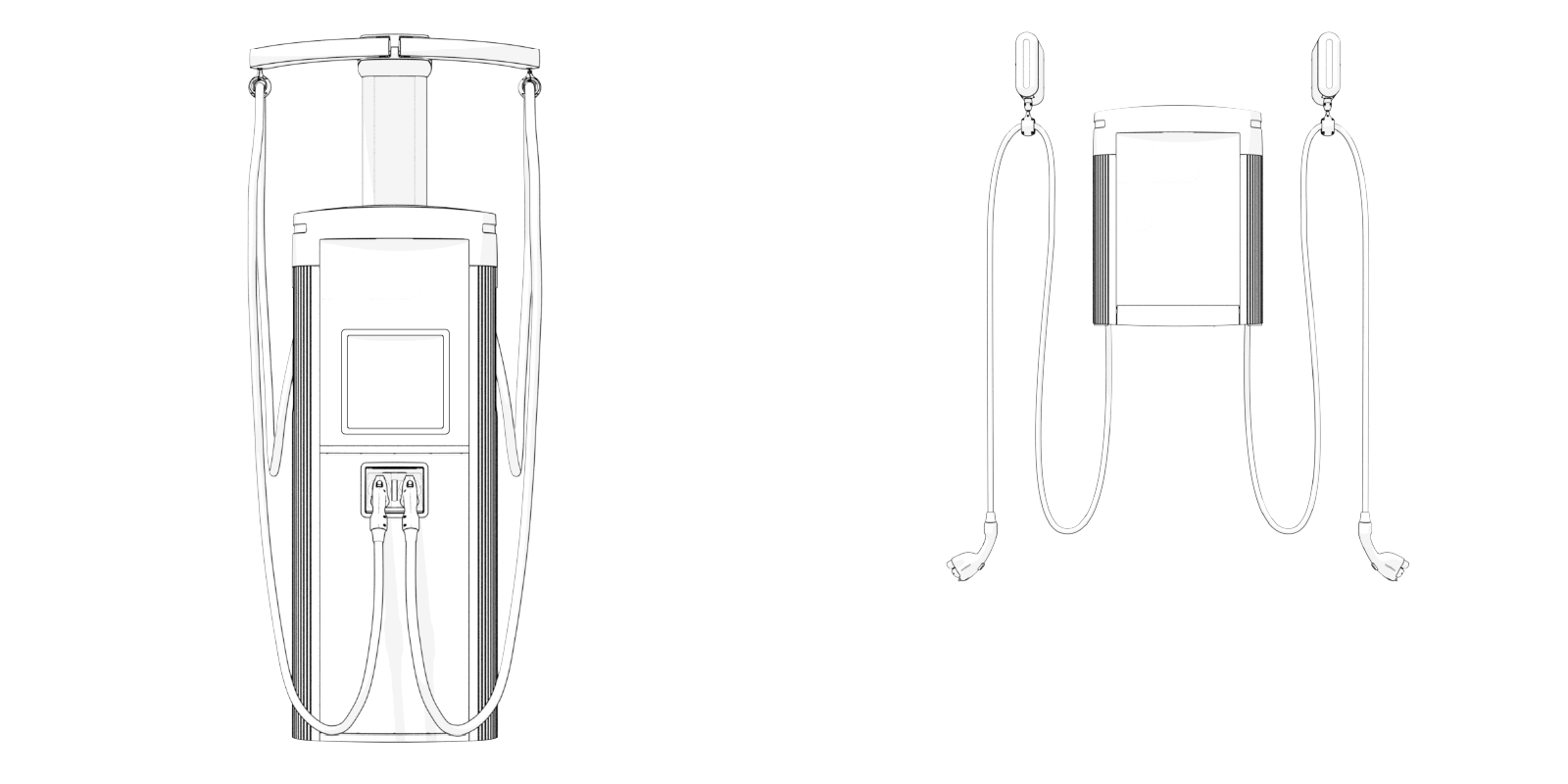
This guide is for pedestal-mount Power Link 2000s. If your unit is an overhead-mount Power Link 2000, refer to the Express Distro Overhead-Mount Power Link 2000 Installation Guide, available at ChargePoint Product Reference Documentation.
Charging Cable Type and Quantity
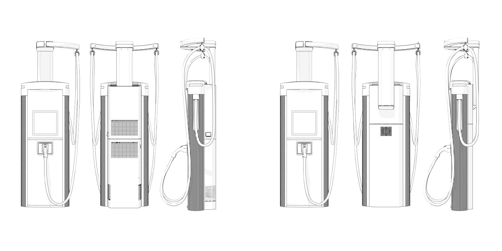
Depending on the charging speed and connectors required, pedestal-mount Power Link 2000s can be installed with one or two liquid-cooled cables (LCC Liquid Cooled Cable) or non-liquid-cooled cables (non-LCC Liquid Cooled Cable). The pedestal-mount Power Link 2000 with LCC Liquid Cooled Cable comes with a liquid cooling system attached to the back of the enclosure.
| Pedestal-Mount with Single or Dual LCC Liquid Cooled Cable |
Pedestal-Mount with Single or Dual Non-LCC Liquid Cooled Cable |
|---|---|
|
|
|
Charging Cable Length and Cable Management Kits
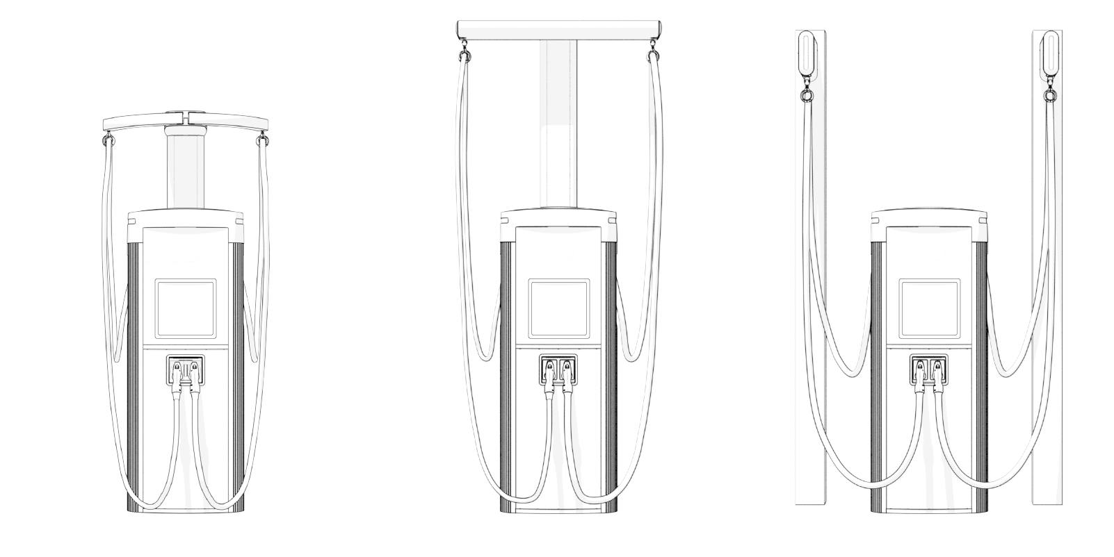
Depending on the required cable reach, the pedestal-mount Power Link 2000 can be installed with a standard cable management kit (CMK Cable Management Kit) to manage standard length (up to 5.8 m or 19 ft) charging cables, or with a tall CMK Cable Management Kit or overhead CMK Cable Management Kit to manage medium length (7.6 m or 25 ft) charging cables. The image below shows the CMK Cable Management Kit options installed with a pedestal-mount Power Link 2000.
| Standard CMK Cable Management Kit |
Tall CMK Cable Management Kit |
Overhead CMK Cable Management Kit |
|---|---|---|
|
|
||
The CMKs function as follows:
-
Standard CMK
Cable Management Kit – Moveable arms on the CMK Cable Management Kit swing suspended charging cables out and forward for charging and retract cables to rest position between charges. The standard CMK Cable Management Kit is available with single or dual swing arms.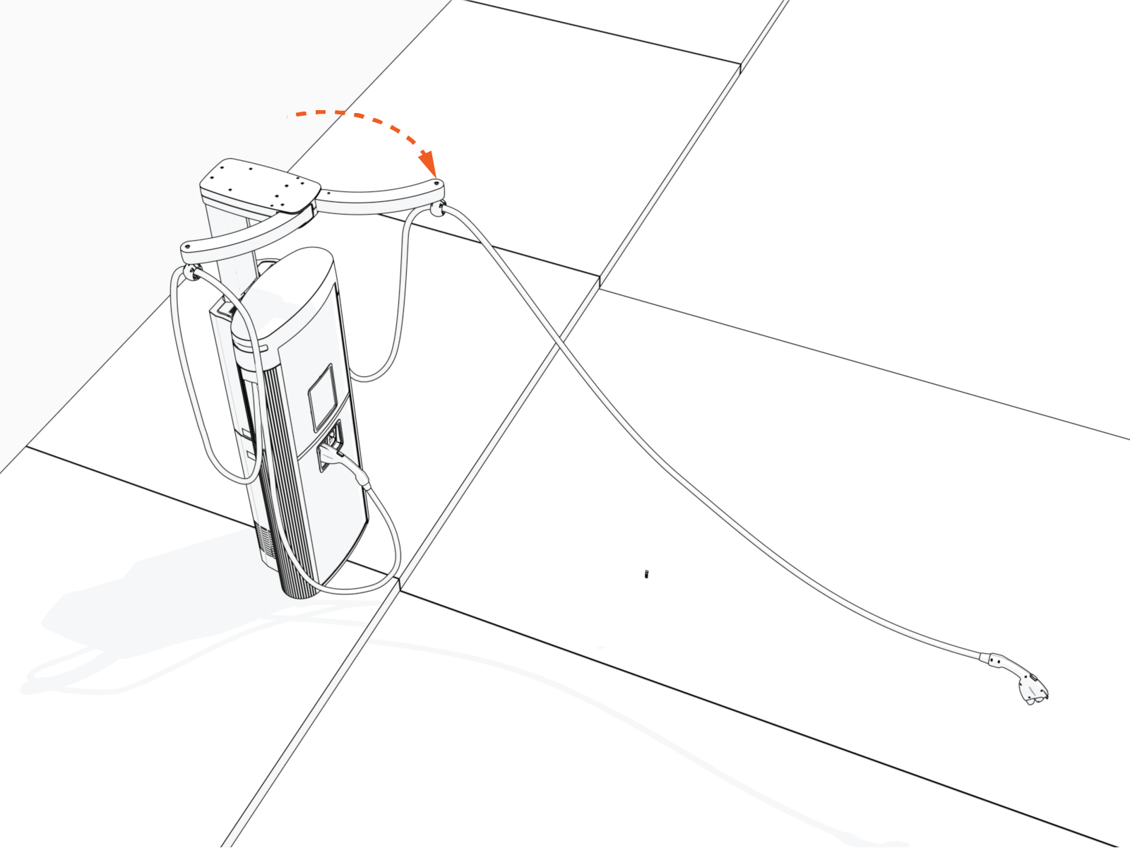
-
Tall CMK
Cable Management Kit – A tether cord extends out of the CMK Cable Management Kit as the suspended charging cable is pulled out and forward for charging. The tether cord retracts when the cable is returned, keeping the cable off the ground throughout use.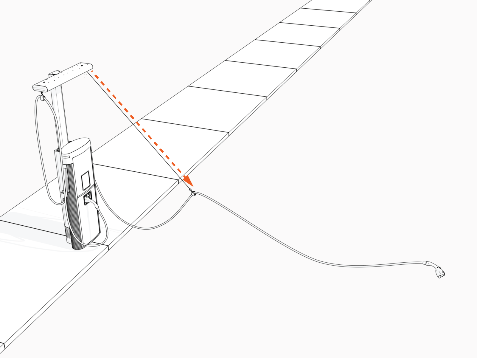
-
Overhead CMK
Cable Management Kit – The CMK Cable Management Kit suspends charging cables and uses a retractable tether cord to support the cable as it is pulled toward the vehicle and to lift it back to its rest position when released.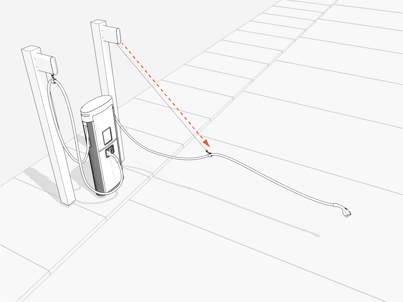
Exterior Parts
The following shows an exterior view of a Power Link 2000 equipped with a standard CMK Cable Management Kit.
|
|
||
|
Front View |
Rear View (non-LCC Liquid Cooled Cable)
|
Rear View (LCC |
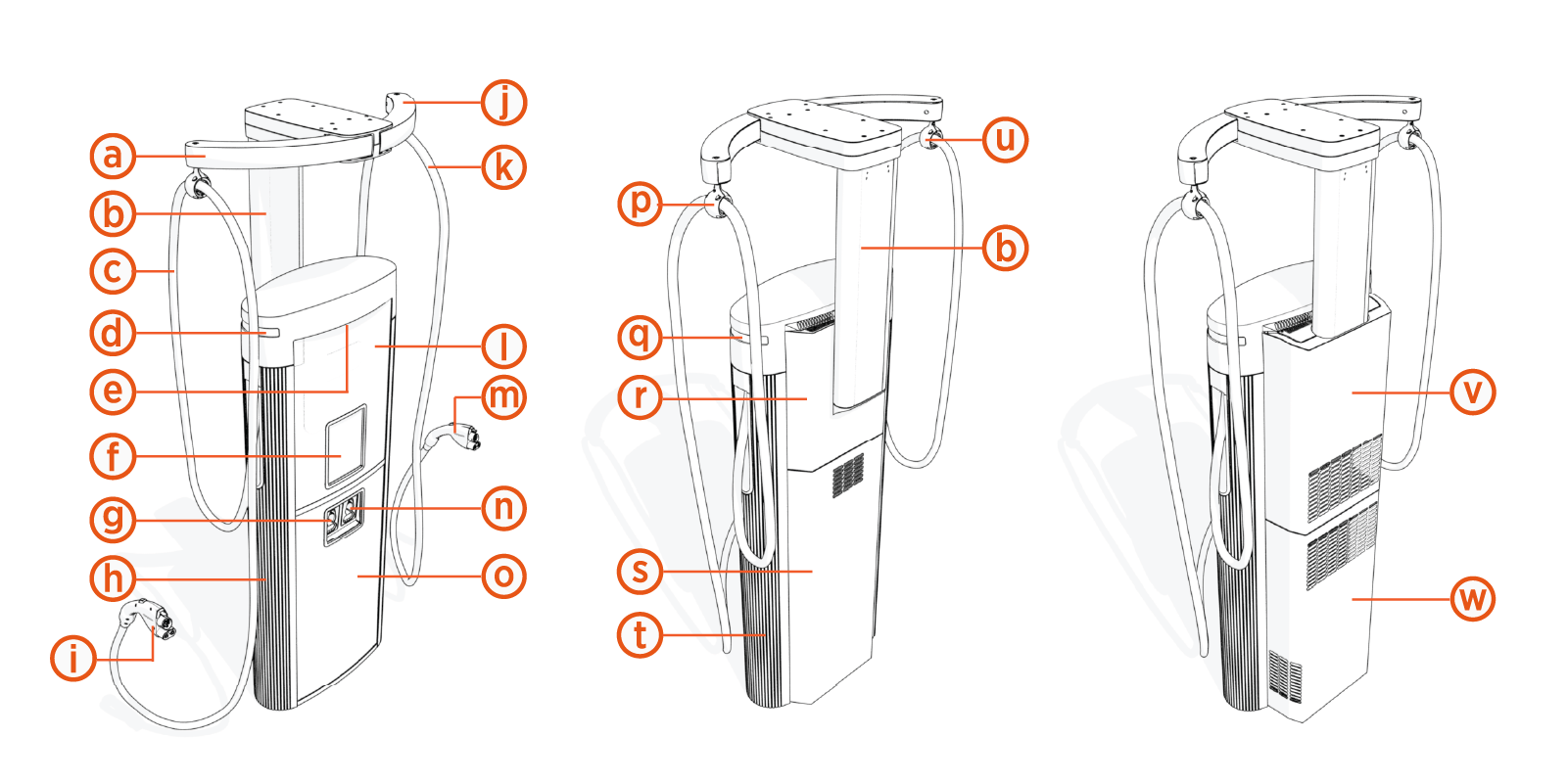
|
Ref |
Part |
Ref | Part |
|---|---|---|---|
| (a) |
Standard CMK |
(m) |
Charging connector, right |
| (b) |
Standard CMK |
(n) |
Holster, right |
| (c) |
Charging cable, left |
(o) |
Lower cover and door (with customizable vinyl) |
| (d) |
Status LED, left |
(p) |
Tetherball, right |
| (e) |
Area downlight (front – illumination side) |
(q) |
Status LED, right |
| (f) |
Display/CCOM |
(r) |
Upper rear cover (non-LCC |
| (g) |
Holster, left |
(s) |
Lower rear cover (non-LCC |
| (h) |
Side panel (side extrusion), left |
(t) | Side panel (side extrusion), right |
| (i) |
Charging connector, left |
(u) |
Tetherball, left |
| (j) |
Standard CMK |
(v) |
Upper rear cover (LCC |
| (k) |
Charging cable, right |
(w) |
Lower rear cover (LCC |
| (l) |
Upper cover and door (with customizable vinyl) |
(*) CCOM Control and Communications Module = Communications and Control Module
Interior Parts
The following shows an interior view of the Power Link 2000, with covers and panels removed.
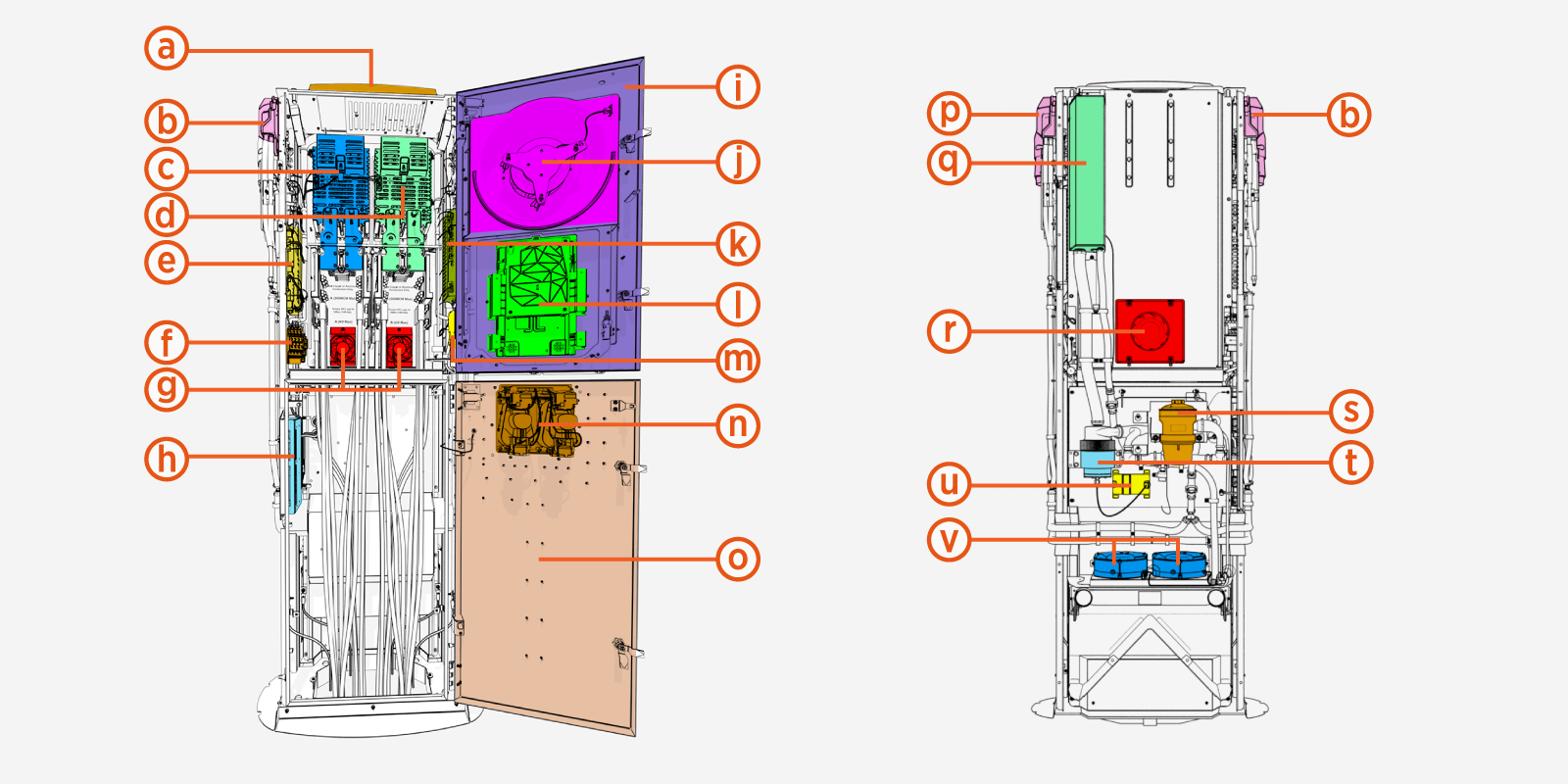
|
|
| Front View | Rear View |
|
Ref |
Part |
Ref | Part |
|---|---|---|---|
| (a) |
Smart antenna (option) |
(l) |
Display/CCOM |
| (b) |
Charging cable assembly, left |
(m) | Smart Ethernet Switch |
| (c) |
DC Input Power Path Assembly A(*) |
(n) |
Holsters, interior view |
| (d) |
DC Input Power Path Assembly B(*) |
(o) |
Lower enclosure door |
| (e) |
Power Link 2000 controller |
(p) |
Charging cable assembly, right |
| (f) |
Terminal block (48 V DC and soft shutdown switch) |
(q) |
Coolant reservoir (LCC |
| (g) |
Internal fans |
(r) |
External fan |
| (h) |
Cooling controller (LCC |
(s) |
Ion filter (LCC |
| (i) |
Upper enclosure door |
(t) |
Pump (LCC |
| (j) |
Door fan |
(u) |
Pump controller (LCC |
| (k) |
Ethernet switch (SSLAN |
(v) | LCC Liquid Cooled Cable fans (LCC Liquid Cooled Cable units only) |
(*) Each power path assembly consists of a DC MID Measuring Instruments Directive Meter module coupled with input/output bus bars.
Wire Entry
-
Stub-up entry: Wires can enter pedestal-mount Power Link 2000s through the bottom of the enclosures via conduits or armored cables laid underground.
-
Surface entry: At sites where the wires cannot be laid underground, they can enter into pedestal-mount Power Link 2000s through the rear side of the enclosures via conduits or armored cables laid above ground. For more information, refer to Appendix A: Surface Conduit Entry Kit Installation.
System Description
The Power Link 2000 is a single-port or dual-port DC charging dispenser designed to interface with upstream ChargePoint Express power cabinets such as Express Solo or Power Block 2000.
The Power Link 2000 is equipped with up to two independent DC power paths:
-
Power Path A – serves the left charging point
-
Power Path B – serves the right charging point
Each power path may be configured to receive DC power from an upstream power cabinet and uses internal switching components to safely connect or disconnect power to each charging cable.
The Power Link 2000 also receives 48 V DC auxiliary power from the upstream cabinet's Auxiliary Power Supply (AUX PS Auxilary Power Supply). This power supports control electronics, communication hardware, UX systems, and sensor and safety circuits.
In addition, the Power Link 2000 maintains Ethernet communication with the upstream power cabinet for coordination, monitoring, and control.
The Power Link 2000 features an integrated control and safety system:
-
Power Link 2000 Controller – An isolated power-control board with some auxiliary interface functions.
-
Protons – Each power path utilizes a Proton module that contains switching elements for connecting or isolating the EV
Electric Vehicle from the incoming DC supply. The Proton also provides integrated DC metering for monitoring voltage and current delivered to the EV Electric Vehicle. It enables the Power Link 2000 to safely energize the EV Electric Vehicle only after the charging handshake is complete, and it opens safely during faults, door‑open events, or shutdown conditions. The Proton also allows for the same DC power to be connected to multiple power paths in sequential charging applications. -
Control and Communication Module (CCOM
Control and Communications Module) – This module manages local user‑experience hardware, communication interfaces, and connectivity functions within the dispenser. The CCOM Control and Communications Module supports the display, authentication hardware, status indicators, and other UX components, and it provides the communication link between the Power Link 2000 Controller and external systems.
The Power Link 2000 provides an integrated user interface for EV Electric Vehicle drivers, including a high visibility display, authentication hardware (e.g., RFID Radio Frequency IDentification reader, credit card reader), LED status indicators, and a cable management system.
System Interfaces and Sample Architectures
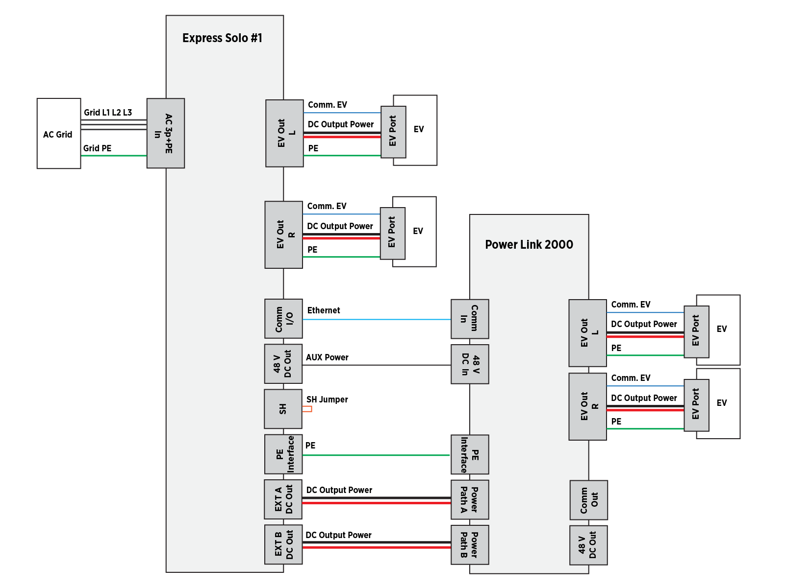
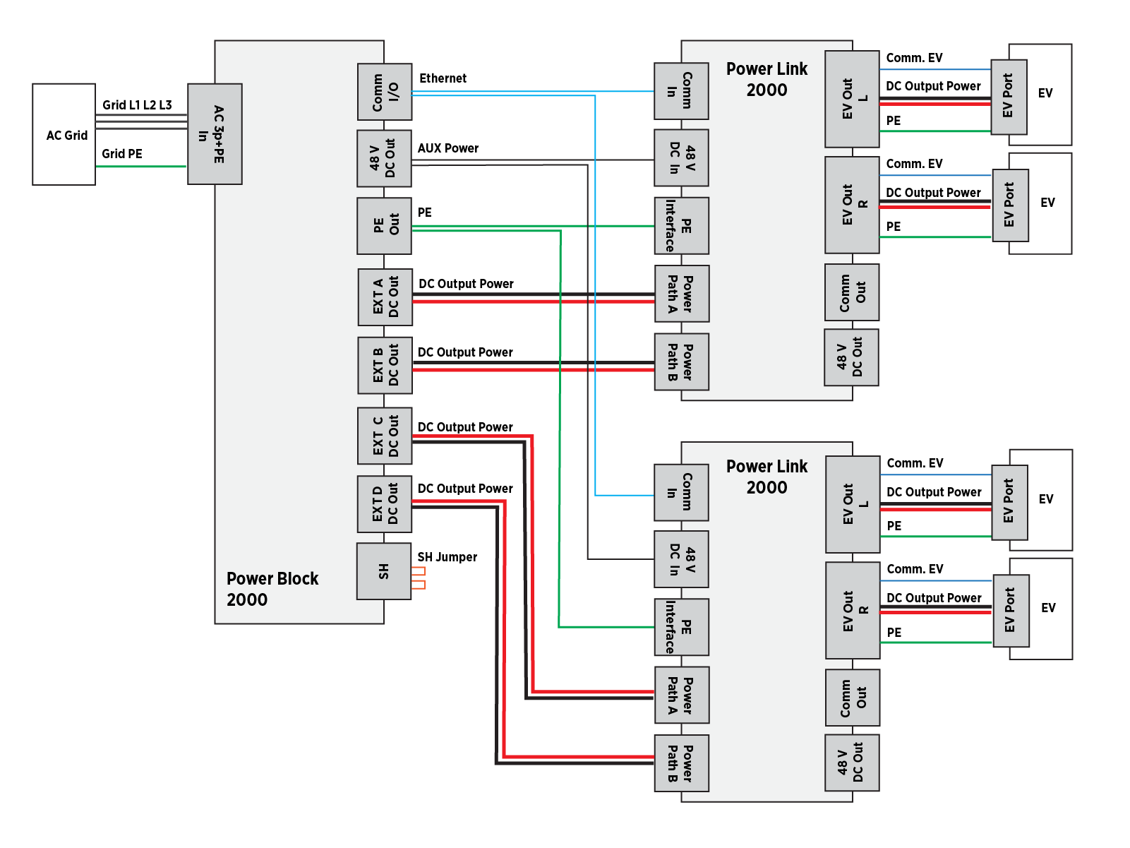
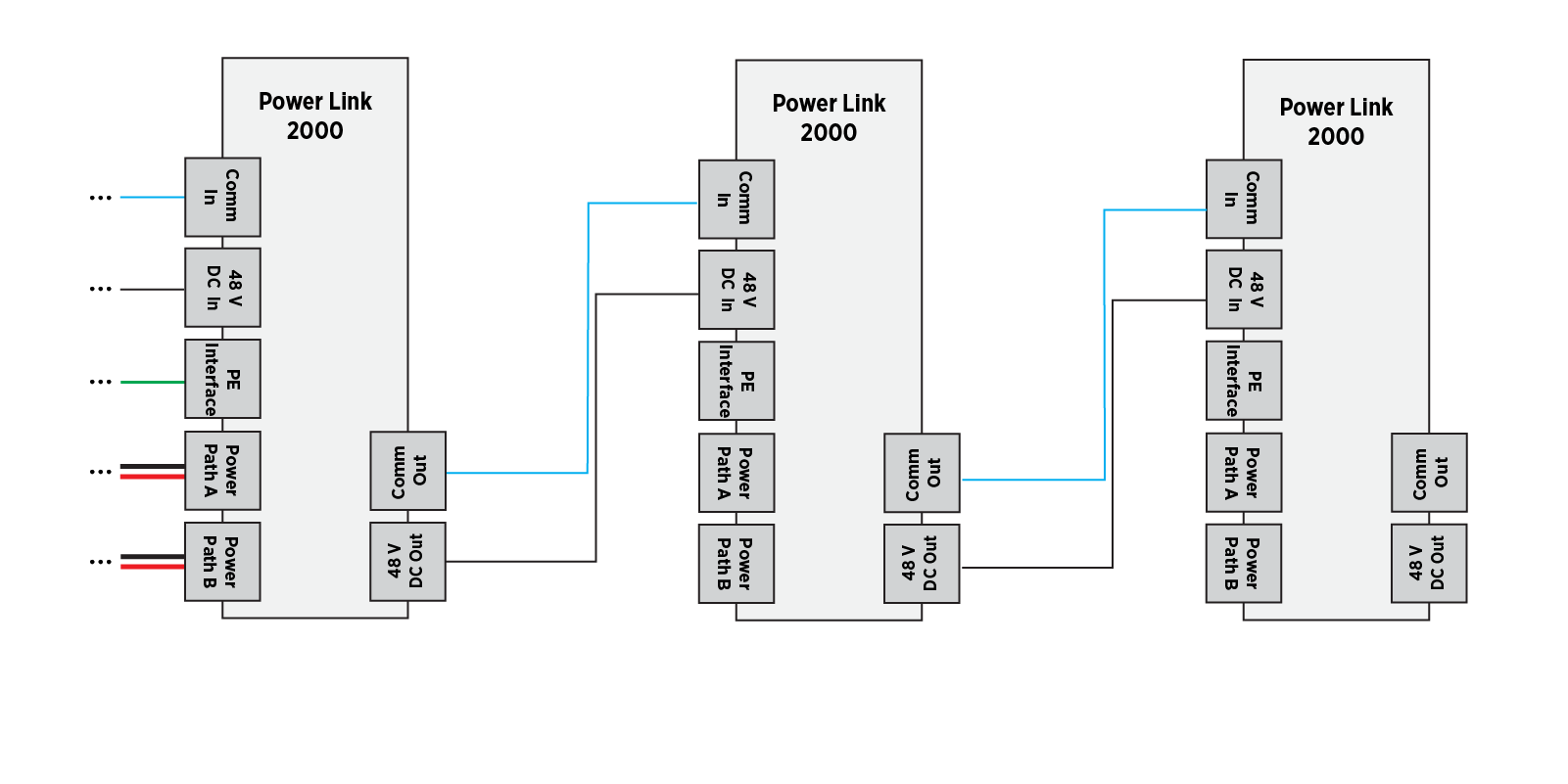
This section provides a high-level overview of the electrical interfaces of a Power Link 2000. The interfaces are illustrated within the context of a few example architectures in which the Power Link 2000 is deployed with upstream power cabinets or in power pass-through configuration.
Below is an example architecture in which an Express Solo power cabinet serves a single Power Link 2000. For further details on Express Solo interfaces, refer to the Express Solo Site Design Guide.
The next diagram shows a configuration in which a Power Block 2000 power cabinet supplies two Power Link 2000 dispensers. For further details on Power Block 2000 interfaces, refer to the Express Distro Power Block 2000 Site Design Guide.
In certain system configurations, Ethernet and 48 V DC auxiliary power from an upstream power cabinet shall be connected from one Power Link 2000 to another, an arrangement known as daisy-chaining.
Power Link 2000 can be configured in many different system architectures, only a few of which are shown above. The actual architecture for each site will vary depending on the number of stations, the charging capacity required at each charging station, charging requirements, and other criteria. If you are a site designer, contact a ChargePoint representative for the ChargePoint-approved wiring architecture for your specific project. Systems configured with non-approved wiring between Power Link 2000 and connected EVSEs may not function as expected. If you are an installer, see the site plan for the architecture specific to the site installation project.
Product Guides
A full suite of guides is available for Power Link 2000, as summarized below.
|
Document |
Content |
Primary Audiences |
|
Datasheet |
Full station specifications |
Site designer, installer, and station owner |
|
Site Design Guide |
Civil, mechanical, and electrical guidelines to scope and construct the site |
Site designer, responsible engineer, contractors, installers |
|
Construction Signoff Form |
Checklists used by contractors to ensure the site is correctly completed and ready for product installation |
Site construction contractor |
|
Installation Guide |
Anchoring, wiring, and powering on |
Installer |
|
Operation and Maintenance Guide |
Operation and preventive maintenance information |
Station owner, facility manager, and technician |
|
Service Guide |
Component replacement procedures, including optional components |
Service technician |
|
Declaration of Conformity |
Statement of conformity with directives |
Purchasers and public |
Access ChargePoint documents at ChargePoint Product Reference Documentation.
