Install Power Link 2000
To install Power Link 2000, complete the following set of steps:
- If the charging station is not installed, commissioned, or serviced by a ChargePoint certified technician using a ChargePoint-approved method, it is excluded from all ChargePoint and other warranties and ChargePoint is not responsible.
- You must be a licensed electrician and complete training at https://www.chargepoint.com/partners/training-certification to become ChargePoint certified and to access ChargePoint's web-based installer tools or ChargePoint Installer app.
If the site has height constraints for installation, contact ChargePoint to get instructions and clearances that you will need for the modified process.
Alternatively, you may use a forklift bracket kit, or a crane with lifting shackles and a spreader bar (constraints may differ among sites).
Install Leveling Nuts
To install leveling nuts, complete the following steps:
-
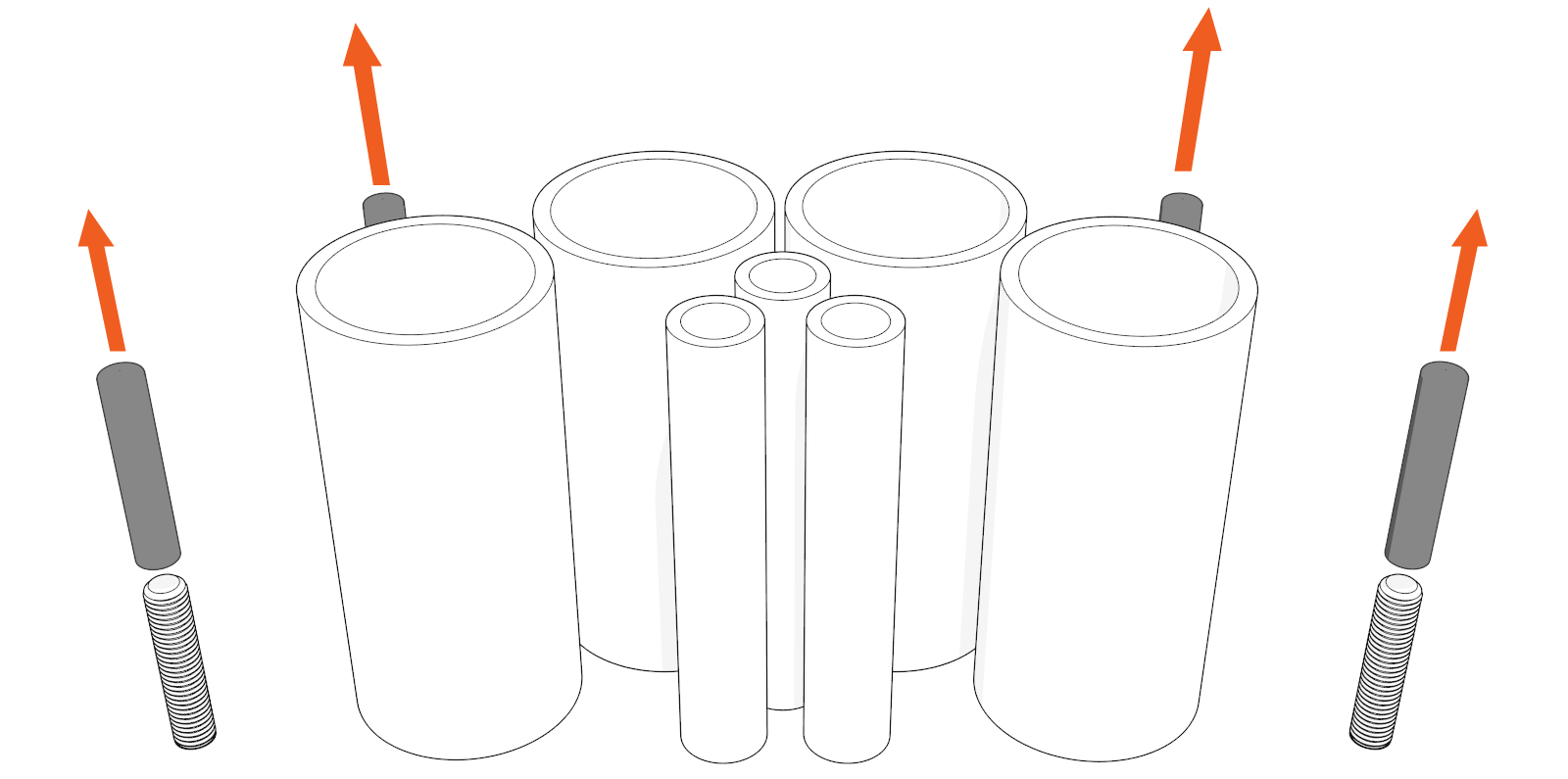
If applicable, remove protective caps (x4).
-
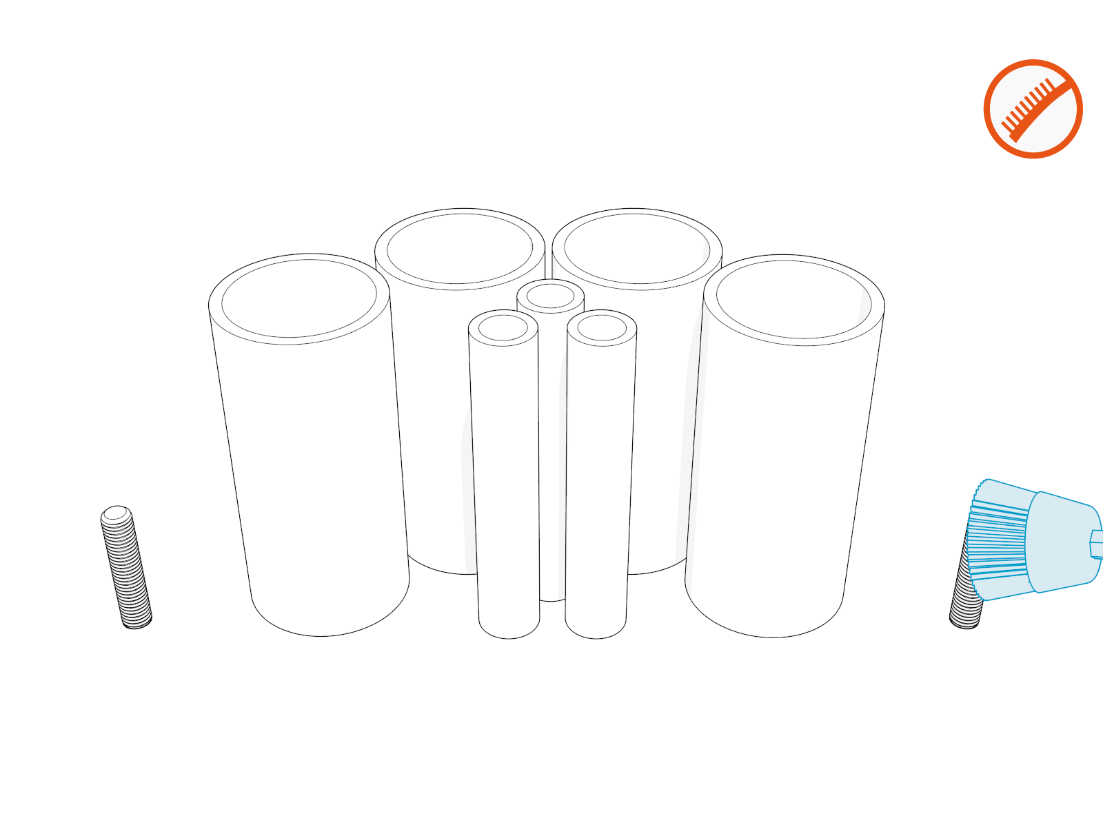
Clean away residue, if any.
-
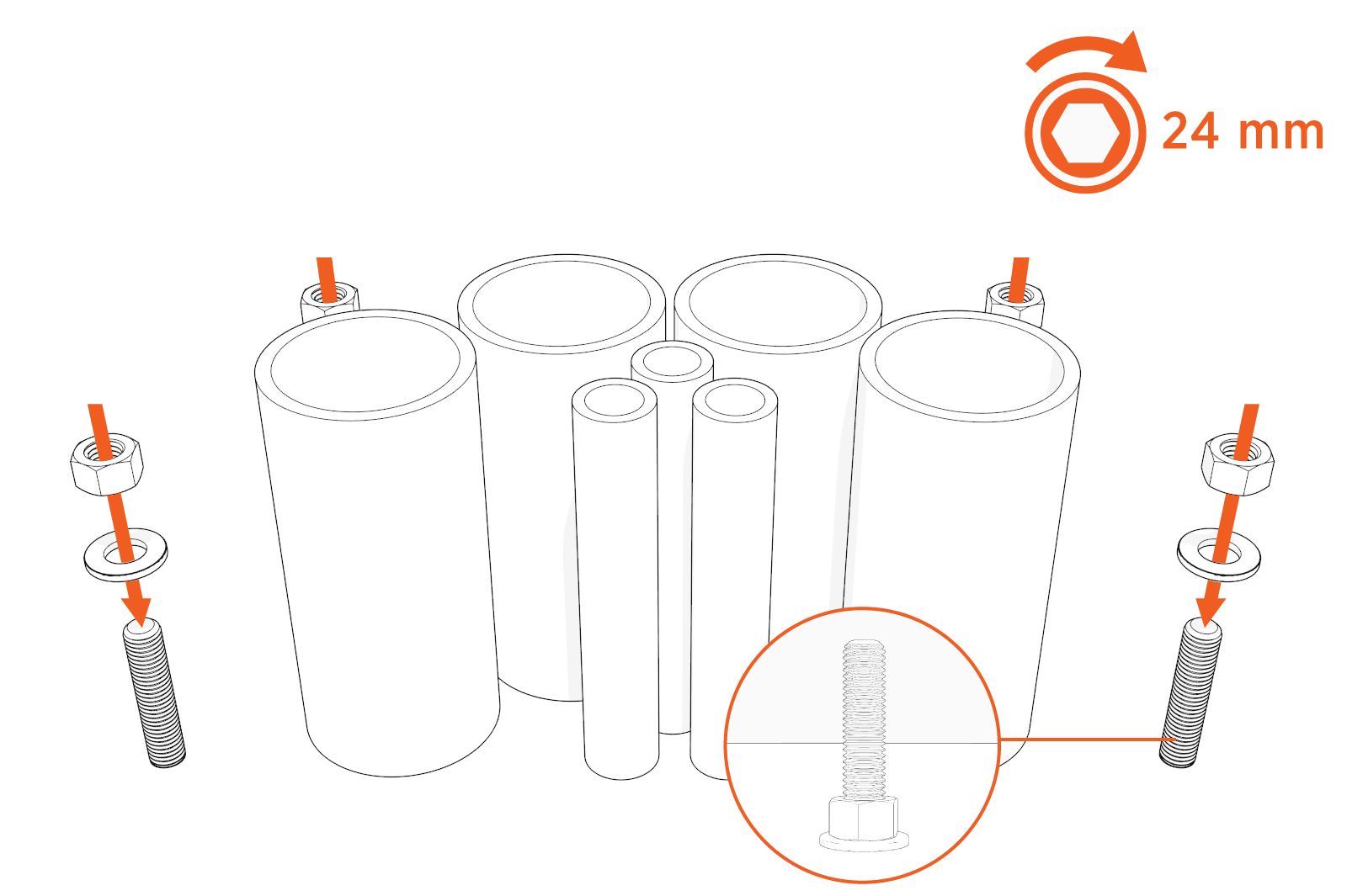
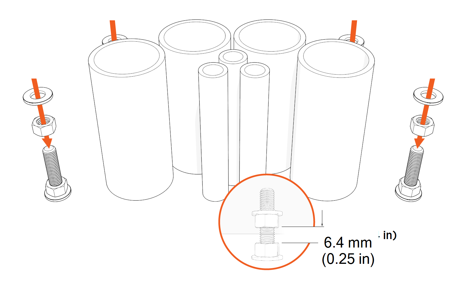
Find the M16 hex nuts and washers shipped with the Power Link 2000.
-
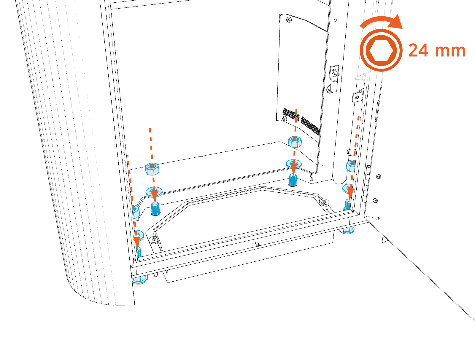
Install M16 washers (x4) and hex nuts (x4) onto the anchor bolts, and flush them against the base. Torque to 54.2 Nm (40 ft-lb).
-
Install another set of M16 hex nuts (x4) and washers (x4) onto the anchor bolts and leave a 6.4 mm (0.25 in) gap between the nuts for leveling the Power Link 2000.
-
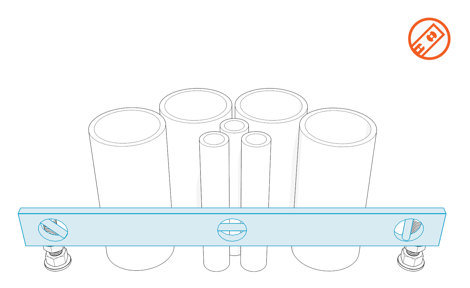
Ensure the nuts are level.
Install Power Link 2000 Assembly
To install Power Link 2000 assembly, complete the following steps:
Position Power Link 2000 Assembly over Anchor Bolts
To position Power Link 2000 assembly over anchor bolts, complete the following steps:
-
Open and unpack the Power Link 2000 package (see Power Link 2000 with non-LCC or Power Link 2000 with LCC).
-
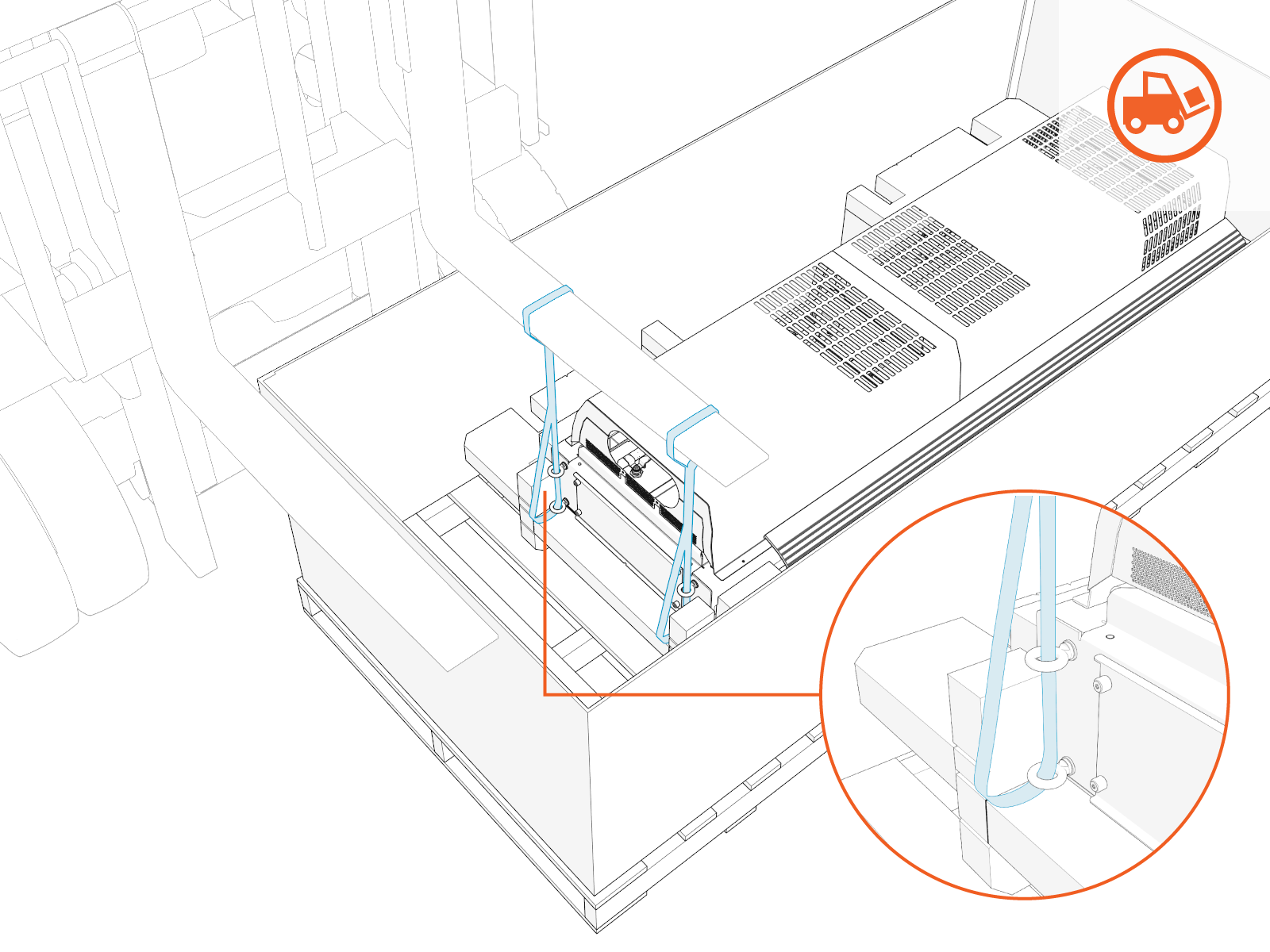
Position the forklift to insert strap loops onto the forks. Make sure that the straps are not near the open ends of the forks. Power Link 2000 comes with straps and eye bolts attached for lifting.
-
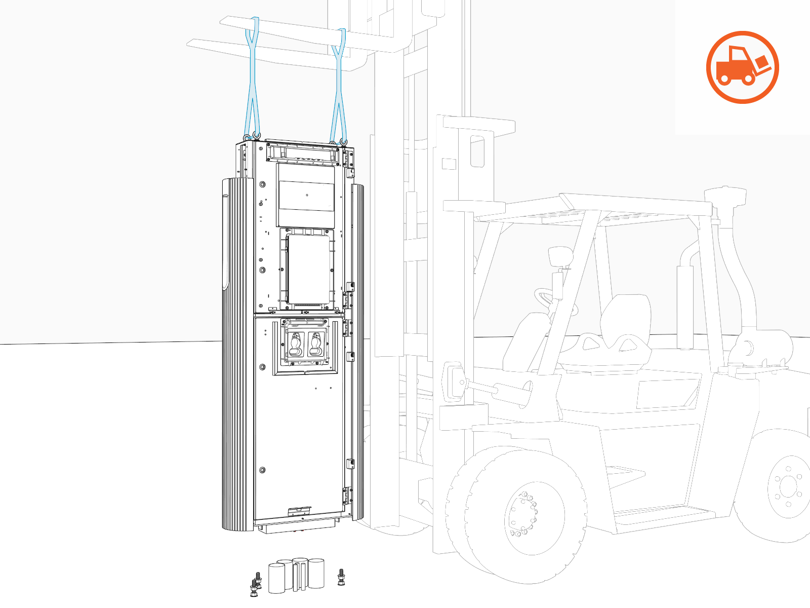
Gradually lift and position Power Link 2000 over the anchor bolts.
Open Enclosure Door
To open enclosure door, complete the following steps:
-
Quarter turn the door latches (x2 per upper and lower enclosure door).
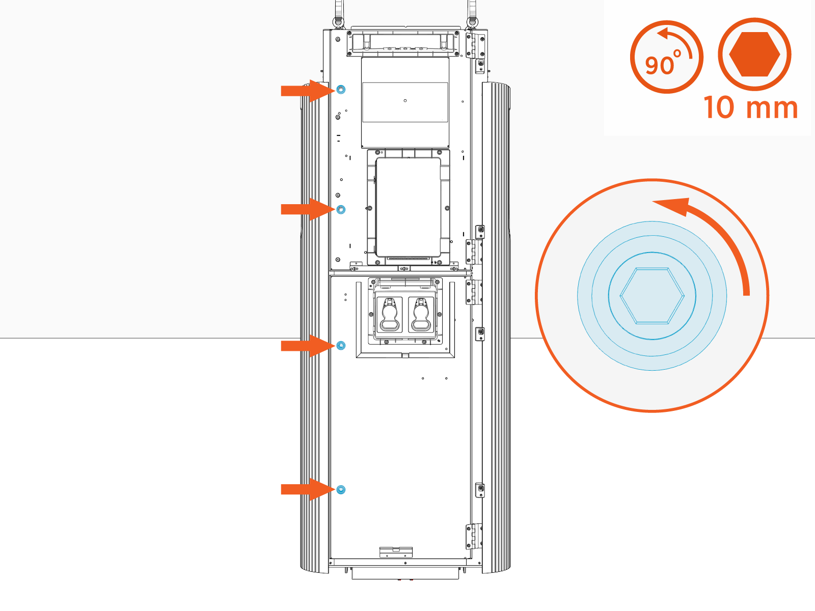
-
Open the door and engage the door stopper (x1 per upper and lower enclosure door).
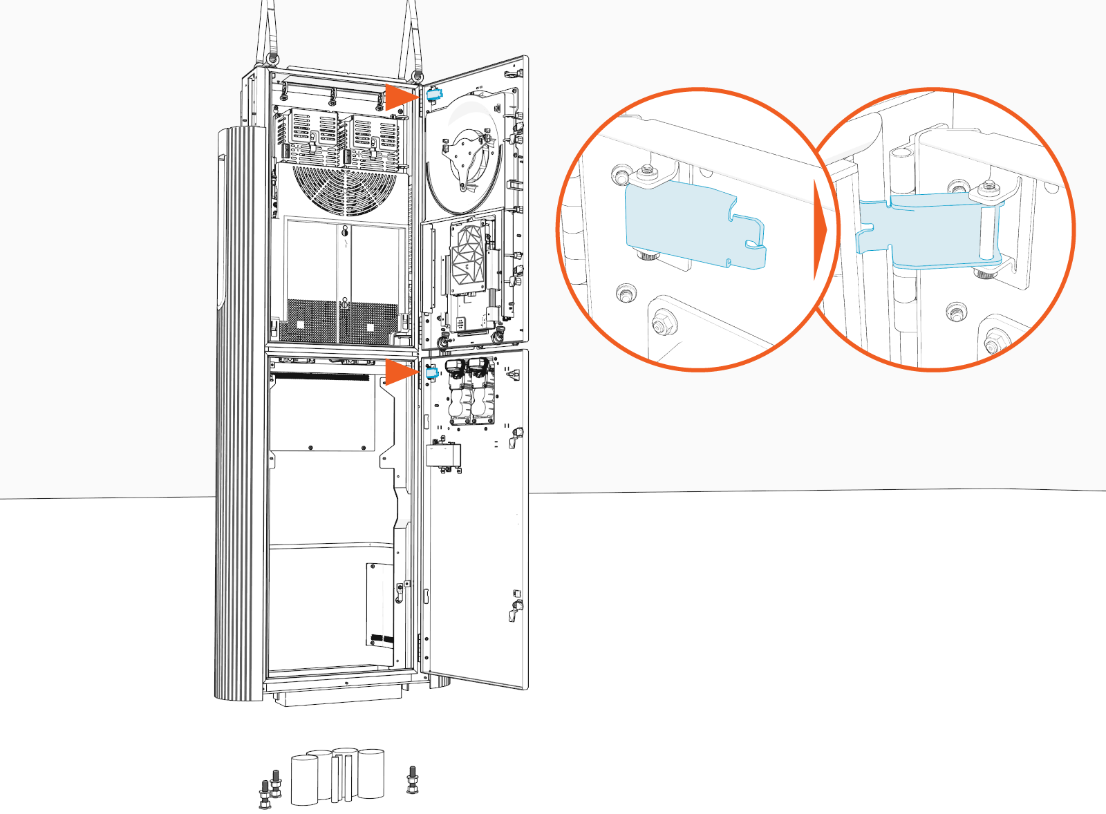
Install Power Link 2000 onto Anchor Bolts
To install Power Link 2000 onto anchor bolts, complete the following steps:
-
Align the anchor bolt holes (x4) on the Power Link 2000 with the anchor bolts and slowly move the Power Link 2000 down to rest it on the leveling nuts.
If the wires have been pulled before mounting the Power Link 2000 or if the site is using armored cables directly buried and exposed from underground without conduits, route wires through conduit opening at the bottom of the Power Link 2000.
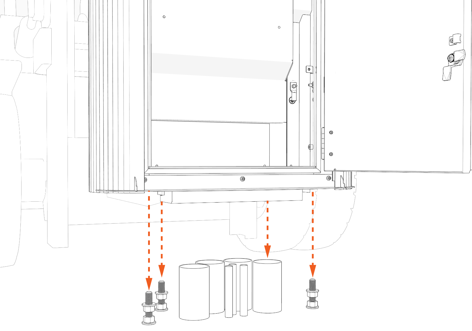
-
Make sure that the Power Link 2000 is resting on the leveling nuts and is level and plumb. If not, adjust the leveling nuts.
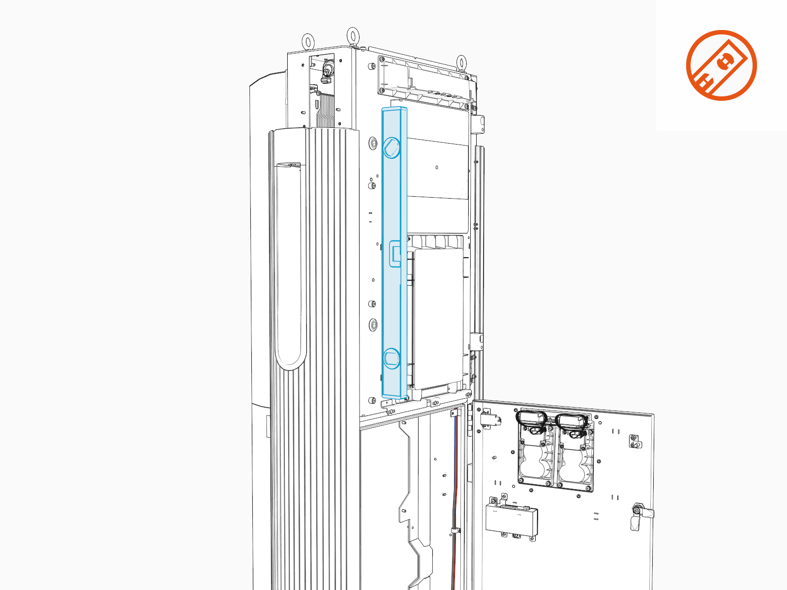
-
When the Power Link 2000 is level and plumb, install another set of M16 washers (x4) and hex nuts (x4) onto the anchor bolts. Torque to 94.9 Nm (70 ft-lb).
-
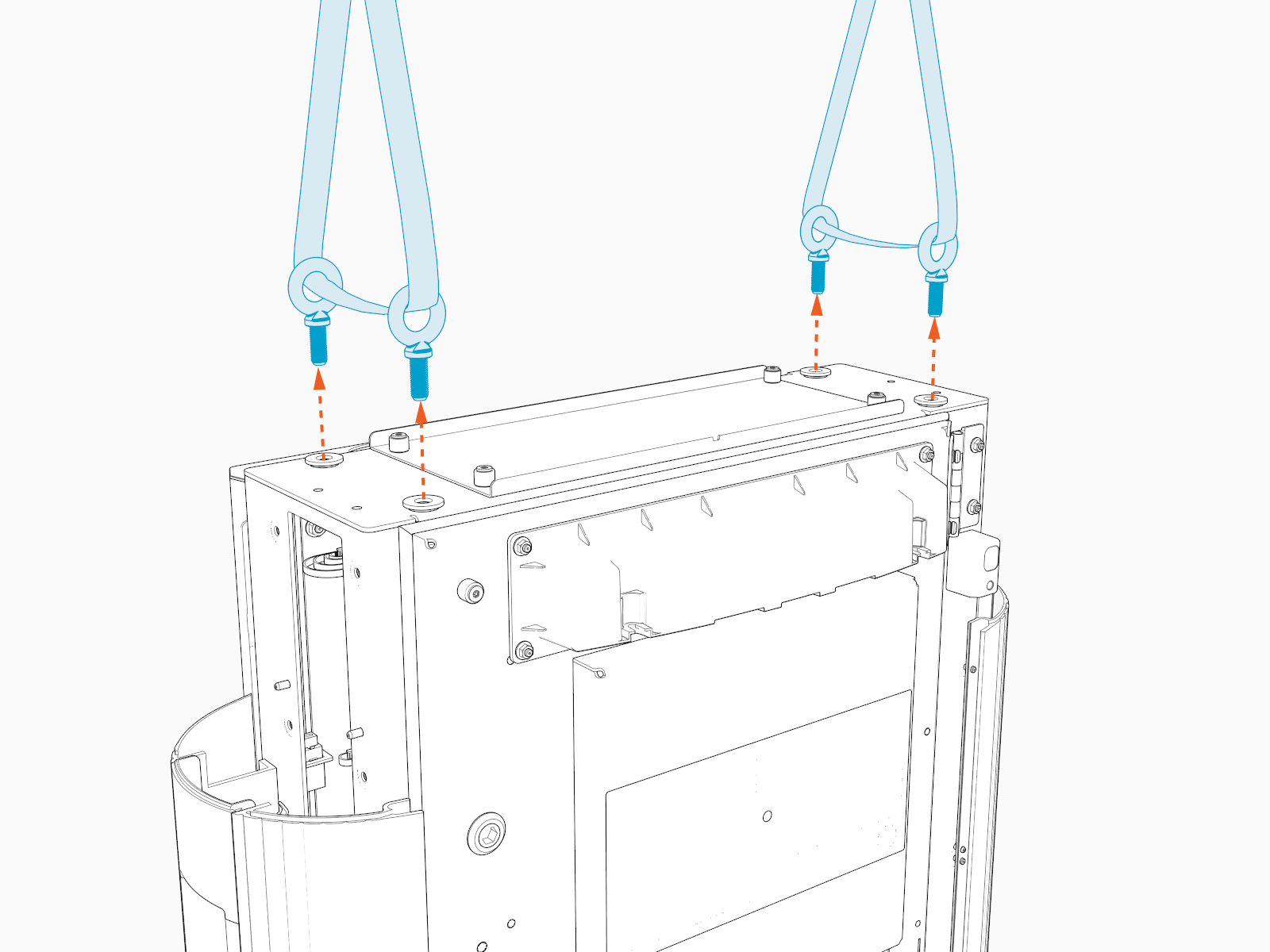
Release the lifting straps, and remove the eye bolts (x4) and rubber washers (x4). Use either an adjustable wrench or screwdriver shaft to loosen the eye bolts.
If wires shall enter the Power Link 2000 by surface conduit entry, install the Surface Conduit Entry (SCE Surface Conduit Entry) Kit. See Appendix A: Surface Conduit Entry Kit Installation.
Access DC Wire Bus Bars and Terminals
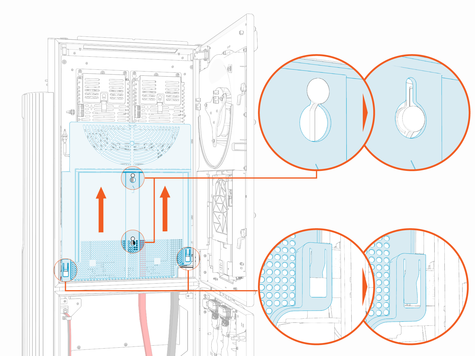
To access the DC wire bus bars and terminals in the upper cabinet, complete the following steps:
Plan for DC Power Path Wire Connect
The physical locations for landing DC power path and ground wires are shown below.
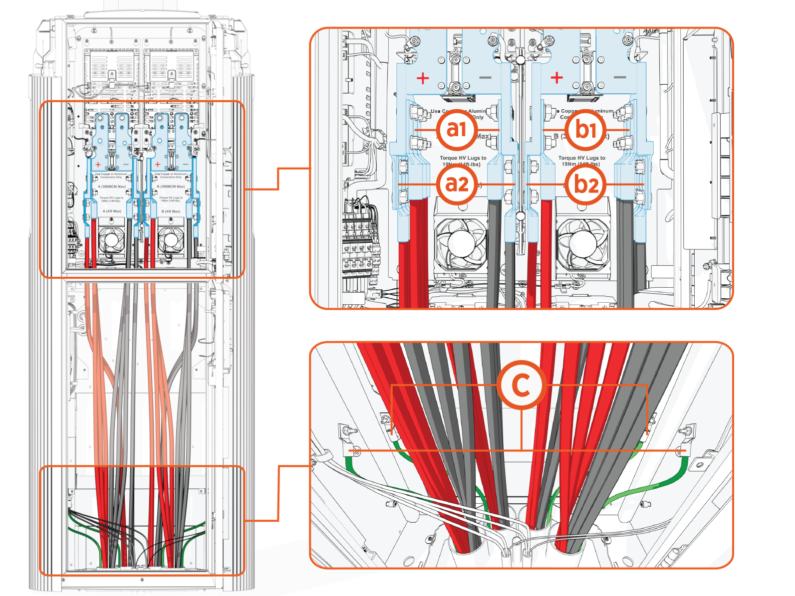
(a1) Power Path A, upper landing
(a2) Power Path A, lower landing
(b1) Power Path B, upper landing
(b2) Power Path B, lower landing
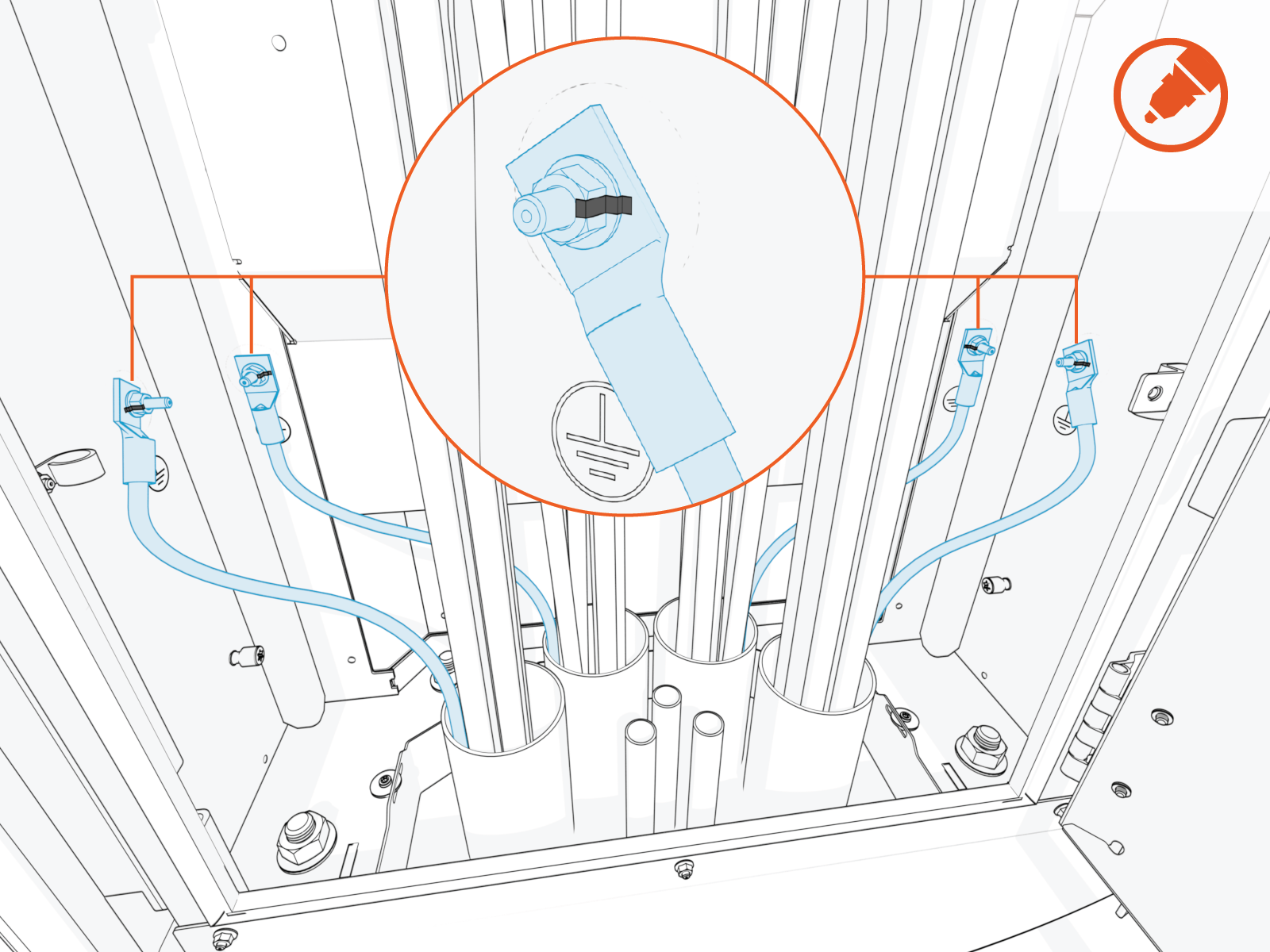
(c) Ground
In this guide, “ground” refers to Protective Earth (PE).
Depending on its configuration, a Power Link 2000 will have one or two independent DC power paths, Power Path A and Power Path B. Power Link 2000s with a single charging cable are configured with Power Path B only.
The upstream power cabinet provides multiple independent DC outputs, and any of these outputs may be connected to either Power Link 2000 power path. The letter labels on the upstream outputs (such as EXT A and EXT B) do not need to match the Power Link 2000 power path labels. For example, an upstream DC output labeled EXT A may be connected to either Power Path A or Power Path B.
How exactly to make connections within a cluster of power cabinets and Power Link 2000s is determined by the Express architecture chosen for the site. Use the site plan single line diagram to understand and plan how to land the wires on the Power Link 2000 DC power path landings. If you require further assistance in this matter, go to chargepoint.com/support and find your region’s technical support number.
Pull, Cut, and Connect Wires
To pull, cut and connect wires, follow the instructions below:
DC Power Path Wires
-
Label the DC power path and ground wires at both ends.
-
Pull wires through the conduits. See How to Pull DC Power Path Wires.
-
In regions that use conduits, wires can be pulled before or after mounting the Power Link 2000. Skip this step if the wires have been pulled before mounting or if the site is using armored cables directly buried and exposed from underground without conduits.
-
Illustrations in this guide depict a Power Link 2000 with two rear conduits and two front conduits. The actual quantity and arrangement of conduits will vary by site.
-
Pull wires through the rear conduits first. Pulling wires through the front conduits restricts access to the rear conduits.
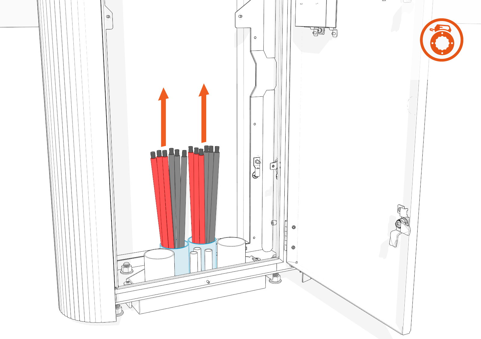
-
-
Arrange wires so they reach the DC power path landings with as little bend as possible. Cut wires to length, taking into account the terminating lug length.
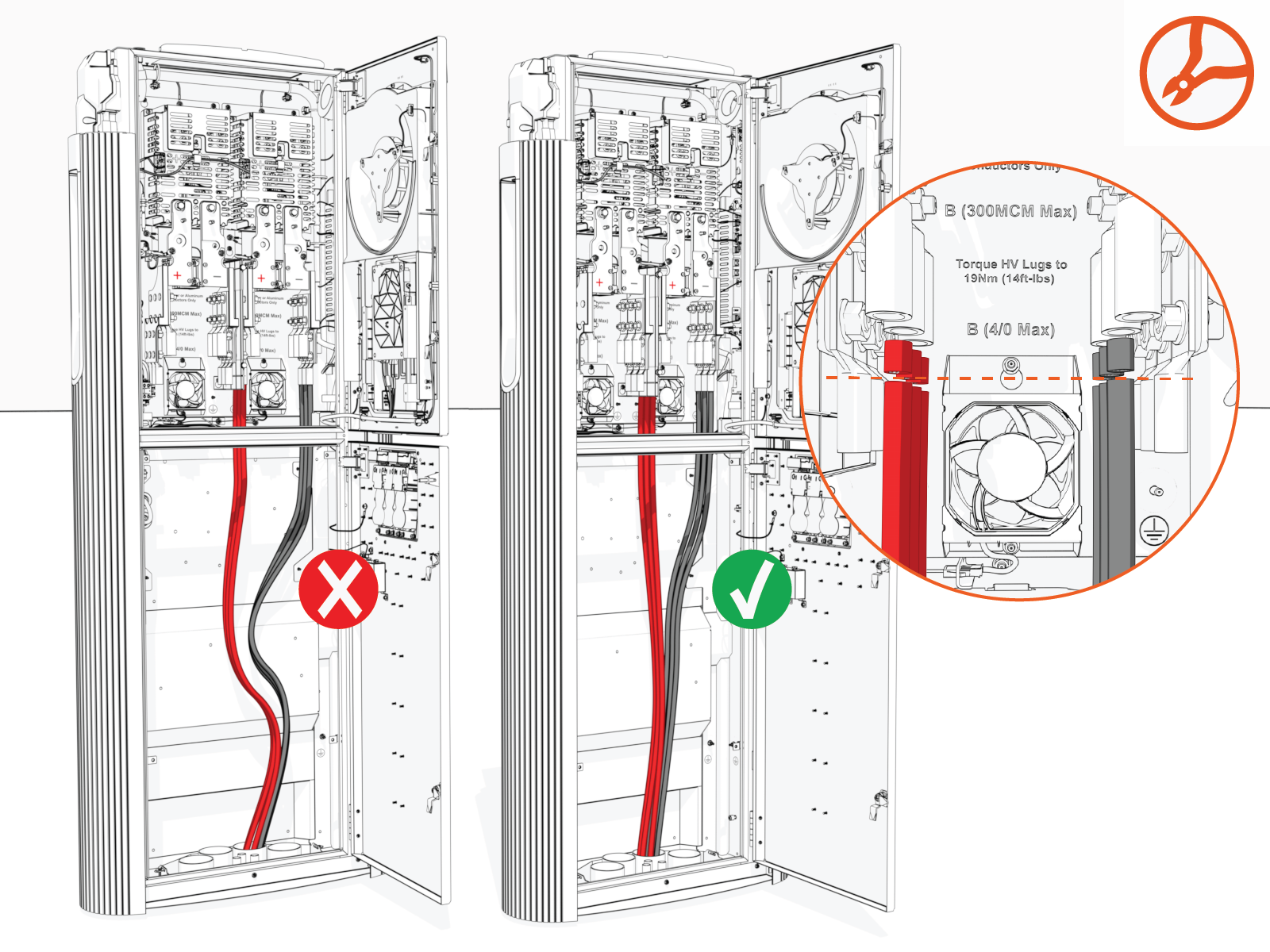
-
Perform insulation resistance test on the DC power path wires. Refer to the High Voltage Wire Insulation Resistance Test Field Guide.
-
Connect the DC power path and ground wires. See How to Connect DC Power Path and Ground Wires.
Connect wires starting at the lower landings. Landing wires at the upper landings restricts access to the lower landings.-
Connect wires starting at lower landings.
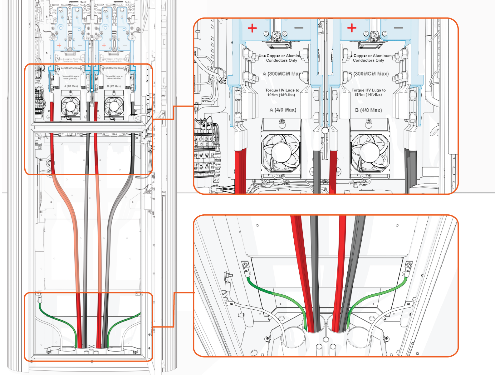
-
Connect wires at upper landings after lower landings are populated.
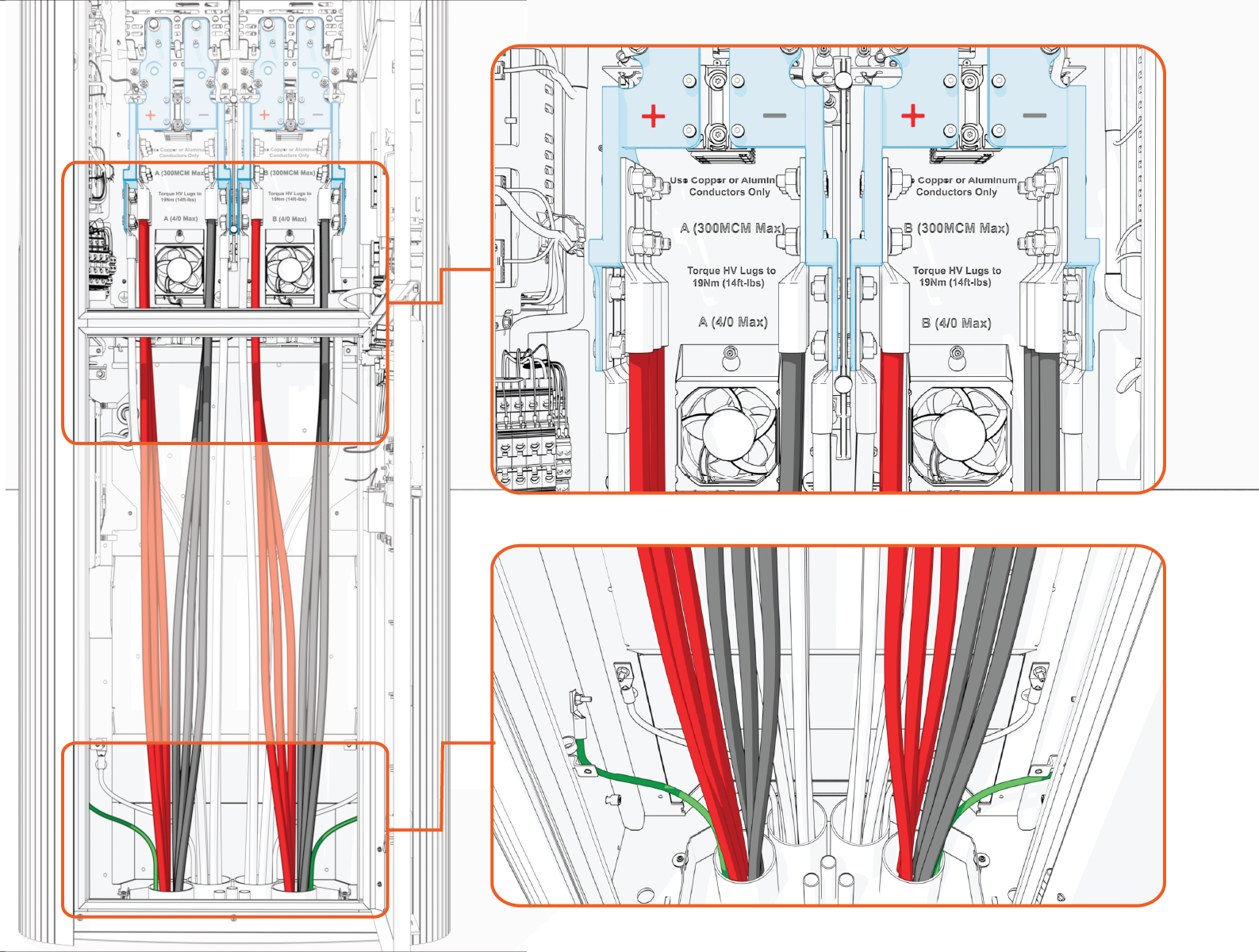
-
48 V DC and Ethernet Wires
-
Label the 48 V DC and Ethernet wires at both ends.
-
Pull the 48 V DC wires and Ethernet cables through the conduits.
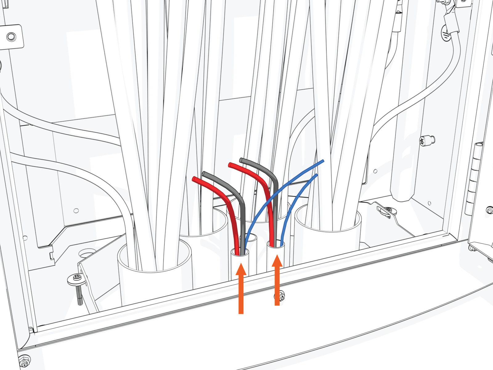
-
Connect the 48 V DC wires and Ethernet cables. See How to Connect 48 V DC and Ethernet Wires.
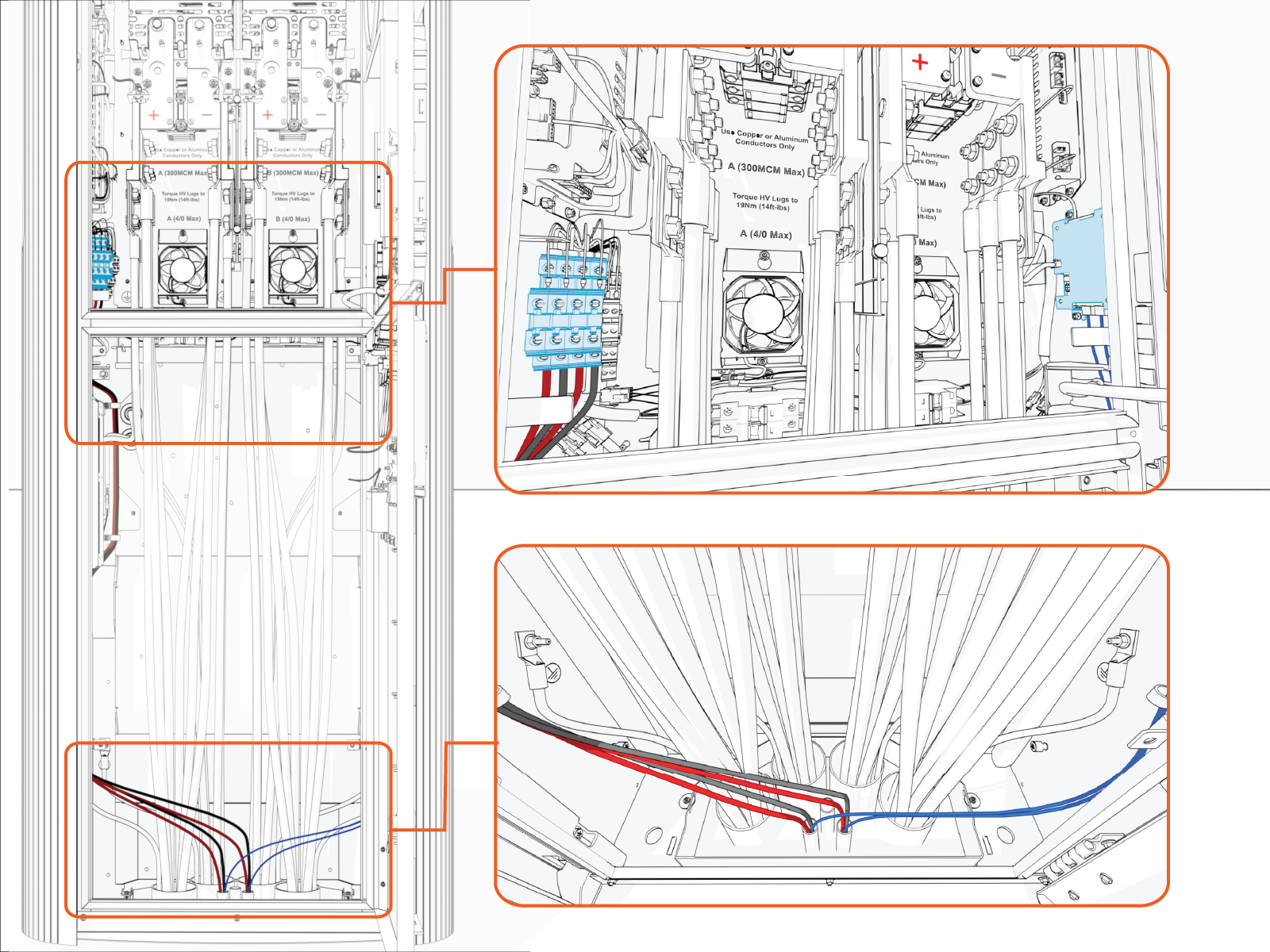
How to Pull DC Power Path Wires
To pull the DC power path wires, complete the following steps:
-
Arrange wires such that the positive wires (red) arrive on the left side and negative wires (black) arrive on the right side within the Power Link 2000. This arrangement will help you land wires on their respective poles.
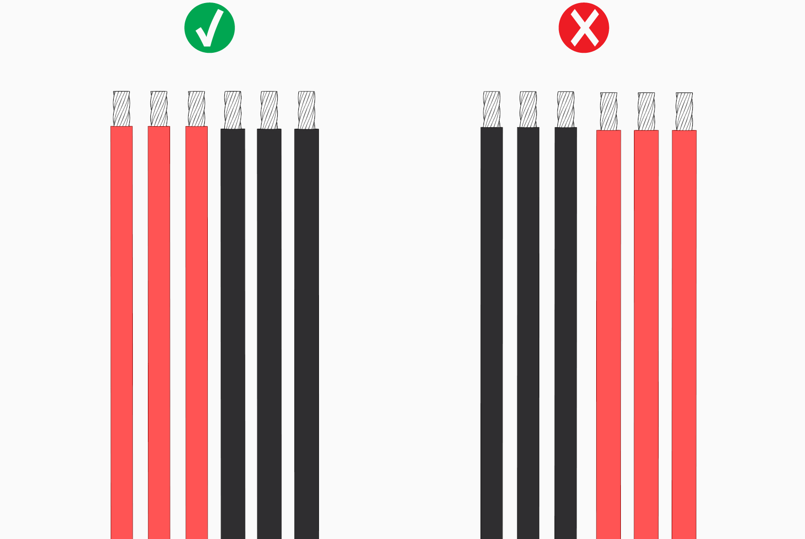
-
If necessary, apply a non-conductive wire pulling lubricant.
-
Pull the wires.
-
Wipe off any remains of wire pulling lubricant if applied.
How to Connect DC Power Path and Ground Wires
Before you begin, make note of the following:
- R
efer to the Express Distro Power Link 2000 Site Design Guide for the wire and lug specifications.
-
Make sure no bare conductor is exposed below the lug's barrel. If necessary, heat shrink or tape the exposed area to meet the local code requirements.
-
Wipe off any remains of wire pulling lubricant if applied.
Prepare DC Power Path Wires
To prepare DC power path wires, complete the following steps:
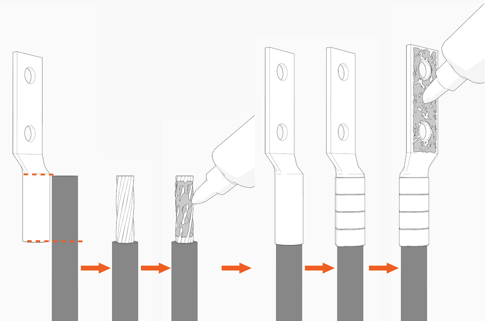
-
Mark the lug's barrel height on the wire terminal.
-
Strip the jacket on the marked terminal. Use a suitable wire stripper, such as Klein tool.
-
If recommended by the wire manufacturer or local code, apply an anti-oxidant joint compound to the stripped wire material to make a gastight joint with the lug.
-
Insert the stripped terminal into the lug's barrel and crimp it. Use a suitable lug crimping tool and/or die recommended by the lug manufacturer.
-
Apply dielectric grease to the lug's tongue surface that comes in contact with the bus bars.
Connect DC Power Path Wires
To connect the DC power path wires, complete the following steps:
-
Identify the location for landing one wire. See Plan for DC Power Path Wire Connect for the wire landing locations.
-
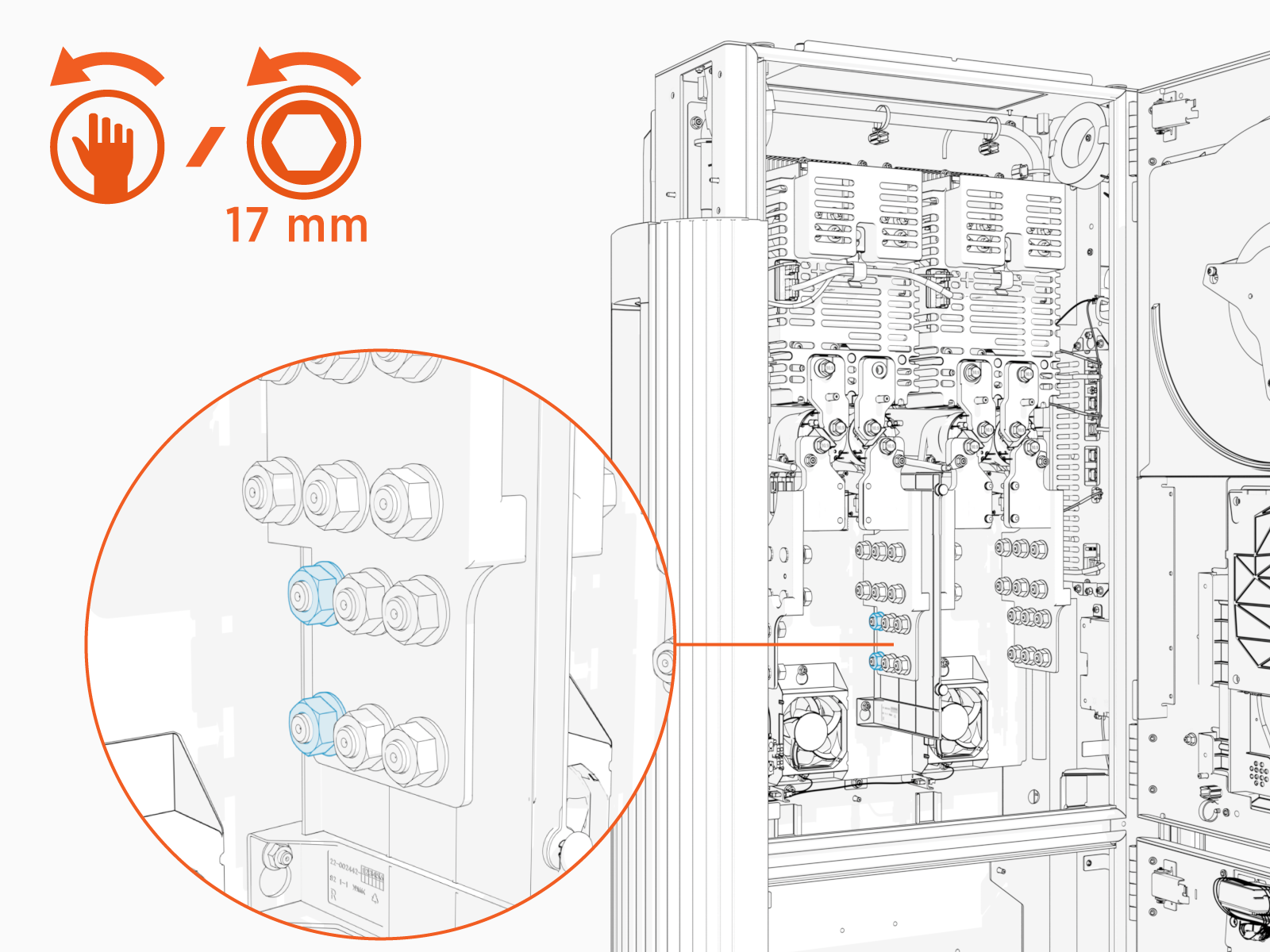
Remove lug nuts.
-
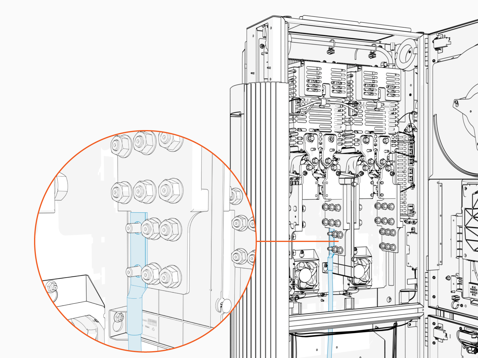
Install the prepared wire onto the studs.
Maintain correct polarity. Install the red (+) conductors on the bus bars labeled "+"and the black (-) conductors on the bus bars labeled "-".
-
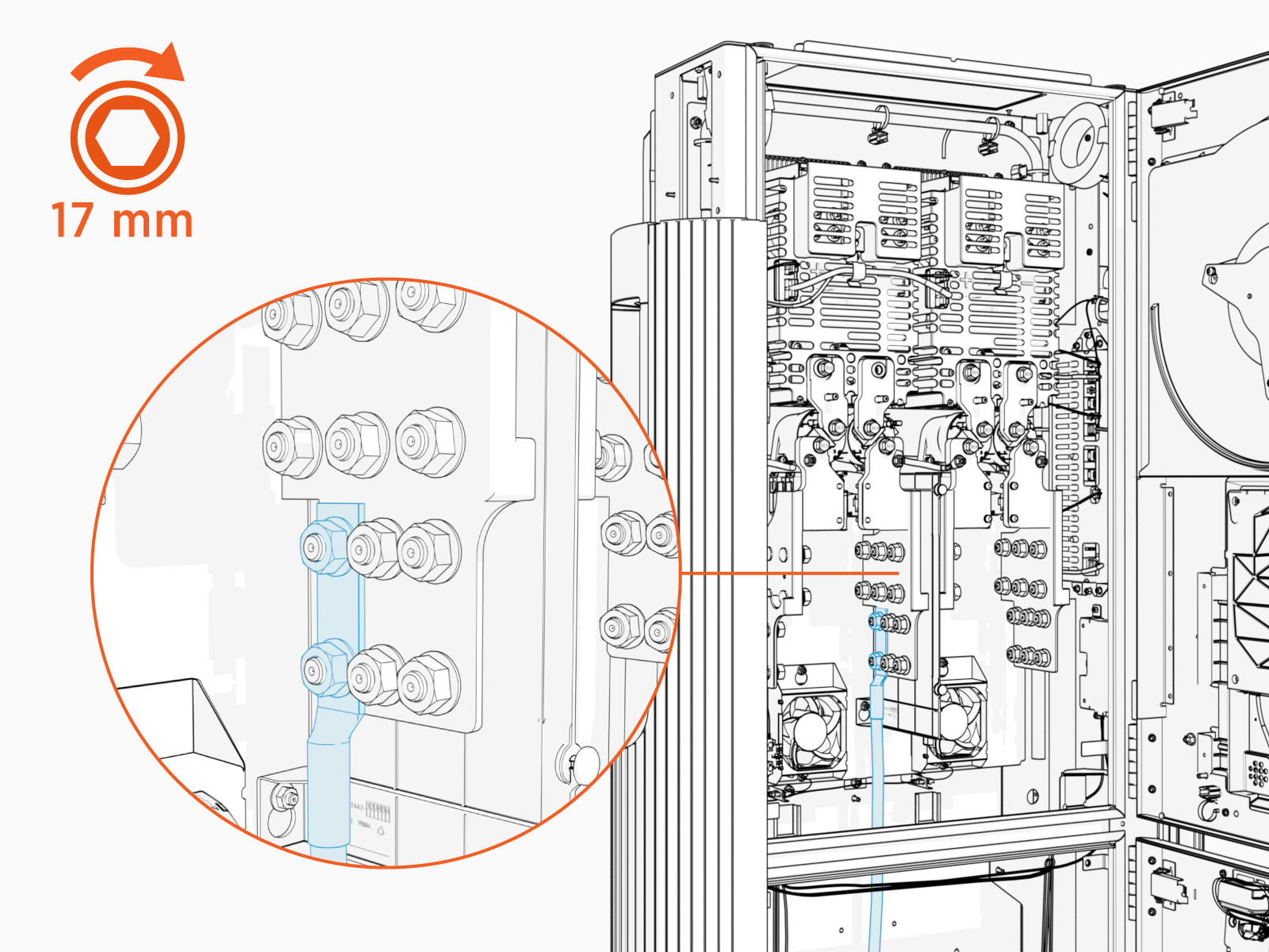
Reinstall the lug nuts and torque them.
Torque the lug nuts to 19 Nm (14 ft-lb).
-
Repeat for all remaining DC power path wires.
-
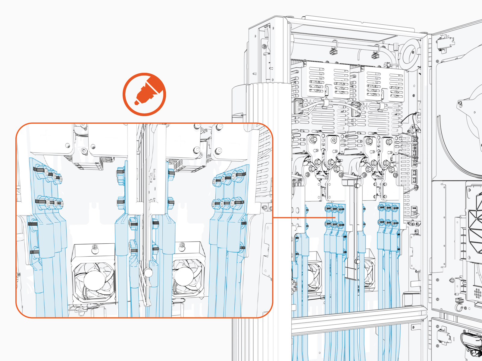
Mark all torqued connections to indicate all lug nuts have been tightened. Torque marks are required to pass post-installation inspection.
Prepare Ground Wires
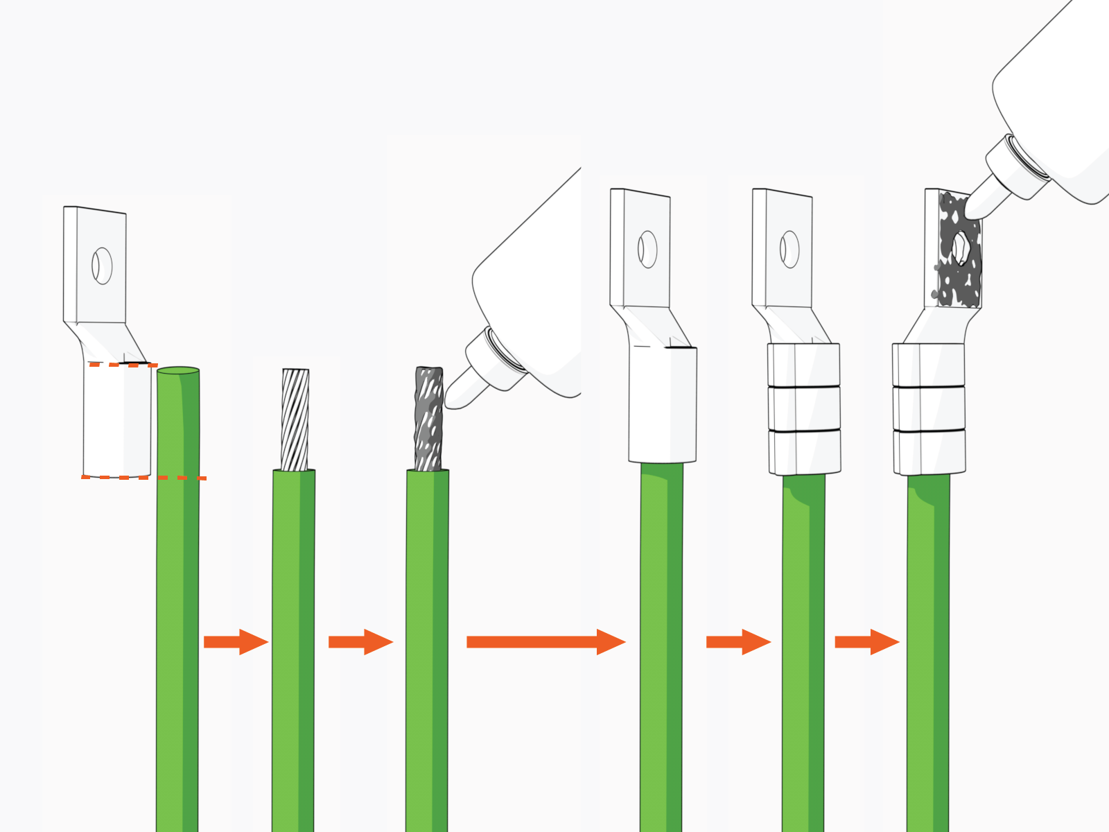
To prepare ground wires, complete the following steps:
-
Mark the lug's barrel height on the wire terminal.
-
Strip the jacket on the marked terminal. Use a suitable wire stripper, such as Klein tool.
-
If recommended by the wire manufacturer or local code, apply an anti-oxidant joint compound to the stripped wire material to make a gastight joint with the lug.
-
Insert the stripped terminal into the lug's barrel and crimp it. Use a suitable lug crimping tool and/or die recommended by the lug manufacturer.
-
Apply dielectric grease to the lug's tongue surface that comes in contact with the bus bars.
Connect Ground Wires
To connect ground wires, complete the following steps:
-
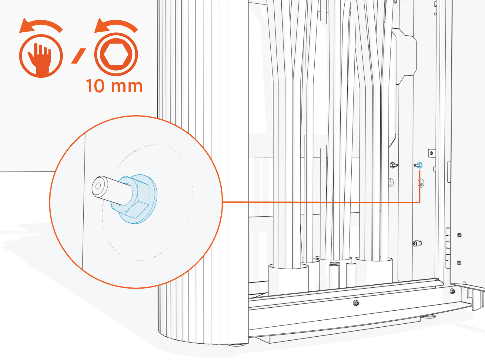
Identify a target ground wire landing stud. See Plan for DC Power Path Wire Connect for the wire landing locations.
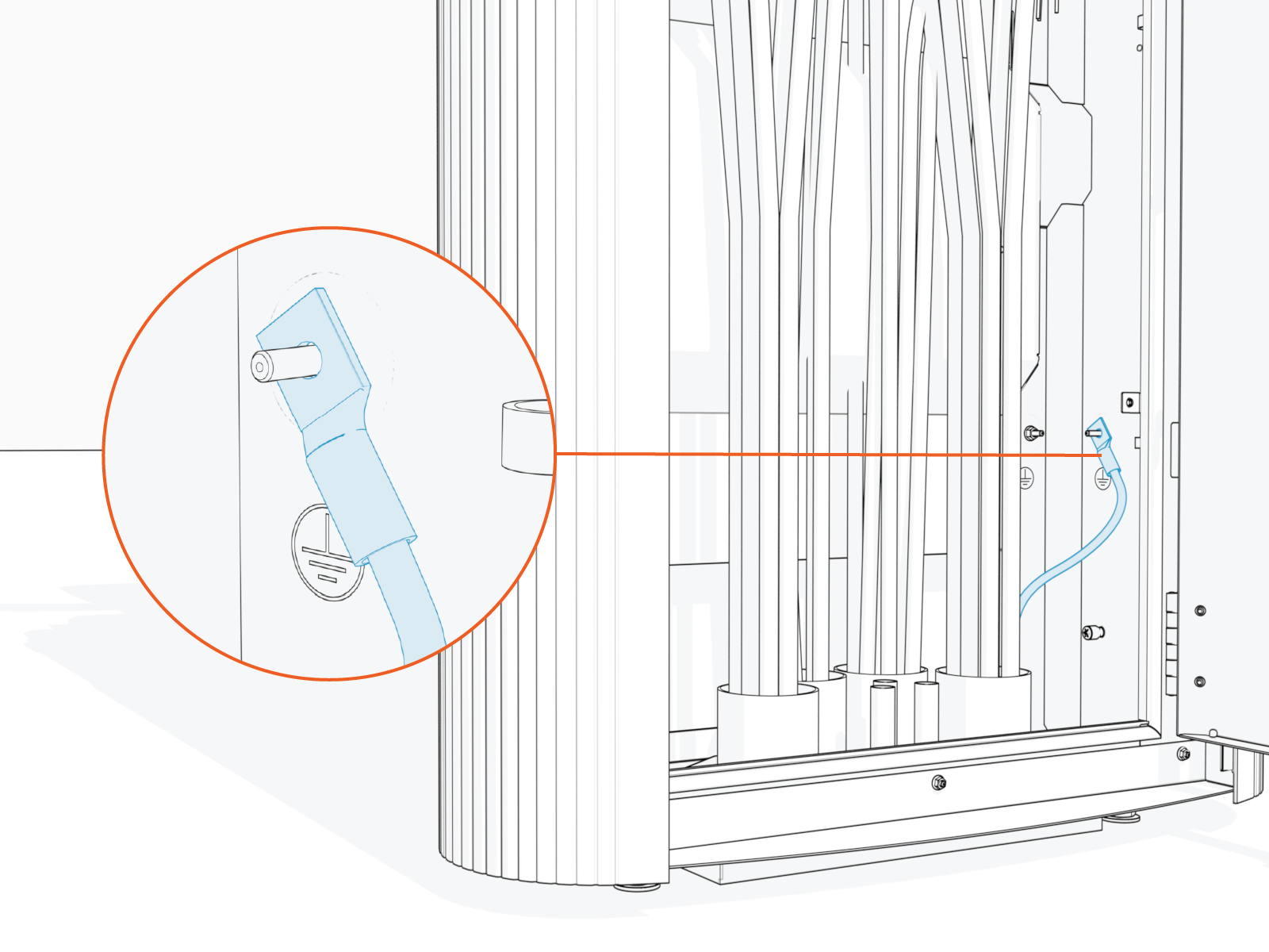
Two ground wires may land on a single stud by stacking the wires on the stud. This is necessary when there are more than four ground connections that must be made.
-
Remove lug nut.
-
Install the prepared wire onto the stud.
-
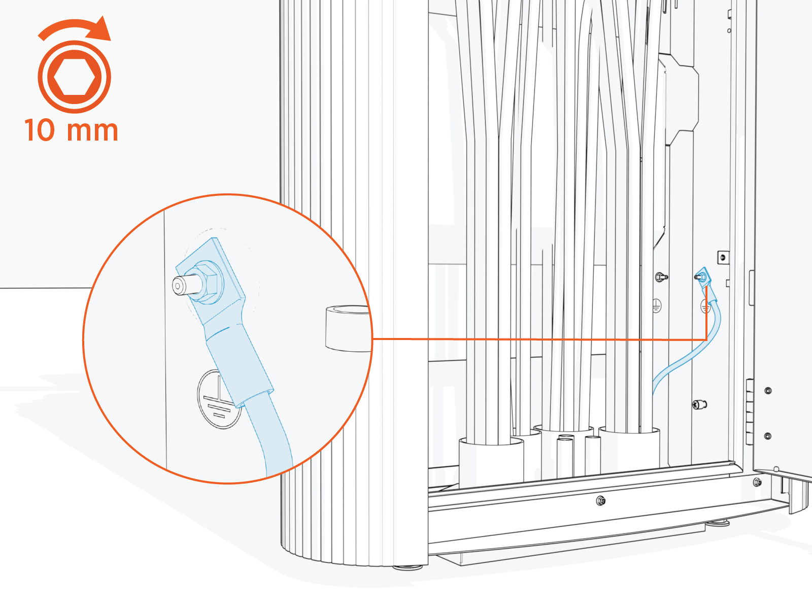
Reinstall the lug nut and apply torque.
Torque the ground wire lug nut to 5.6 Nm (50 in-lb).
-
Repeat for all remaining ground wires.
-
Mark all torqued connections to indicate all lug nuts have been tightened. Torque marks are required to pass post-installation inspection.
How to Connect 48 V DC and Ethernet Wires
To connect 48 V DC and Ethernet wires, follow the instructions below:
Connect 48 V DC Wires
Follow the procedure below for each 48 V DC wire pair.
-
On the 48 V terminal block, identify the target wire insertion points for landing the 48 V DC wire pair.
If the wire terminals do not appear as pictured here, you are using the wrong installation guide. See About This Guide for more information.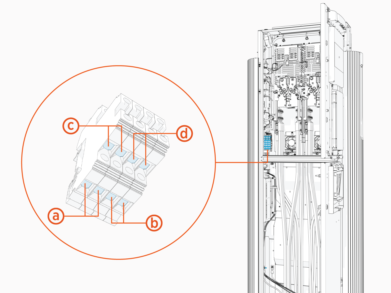
-
48 V DC input, primary
-
48 V DC input, secondary
-
48 V DC output, primary
-
48 V DC output, secondary
-
-
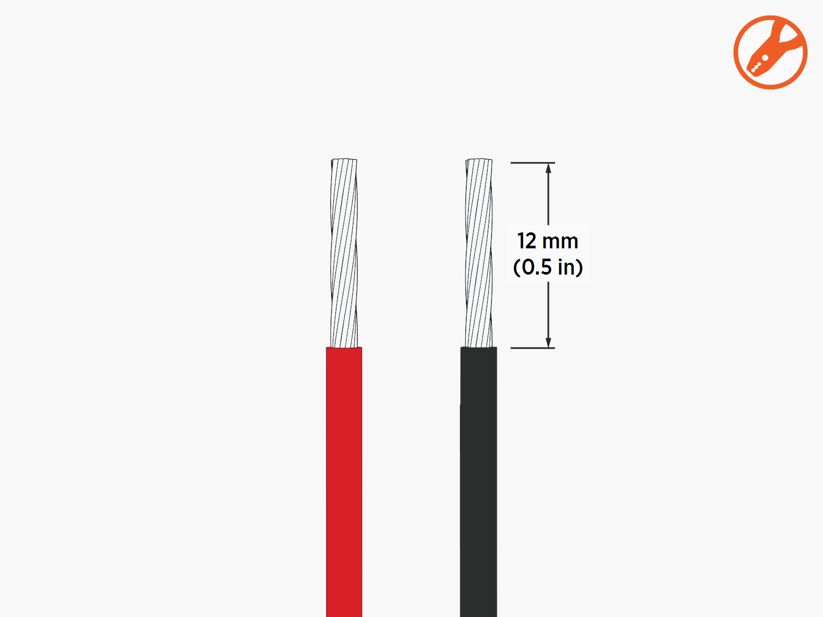
Strip the wire jackets (x2). If using wire ferrules, install the ferrules after stripping the conductors.
-
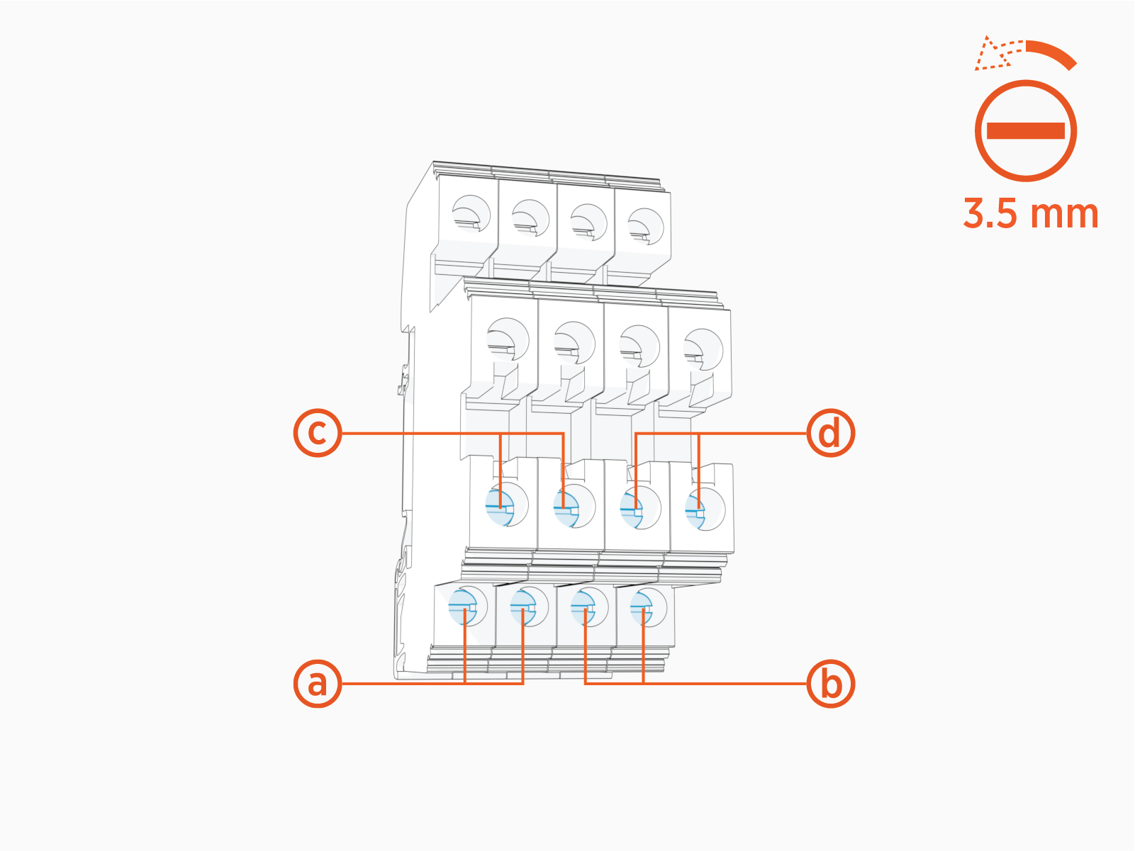
Loosen the wire set screws (x2).
-
48 V DC input, primary
-
48 V DC input, secondary
-
48 V DC output, primary
-
48 V DC output, secondary
-
-
Route wires (x2) through the wireway clamps (if necessary use cable ties) and insert them into the terminal block.
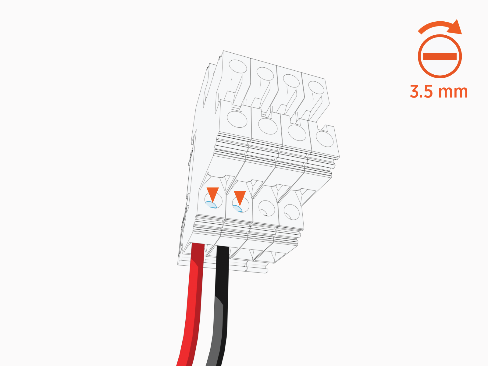
Insert the positive (+) wire into the left terminal. Insert the negative (-) wire into the right terminal. The illustration below depicts insertion of the primary 48 V DC input wire pair.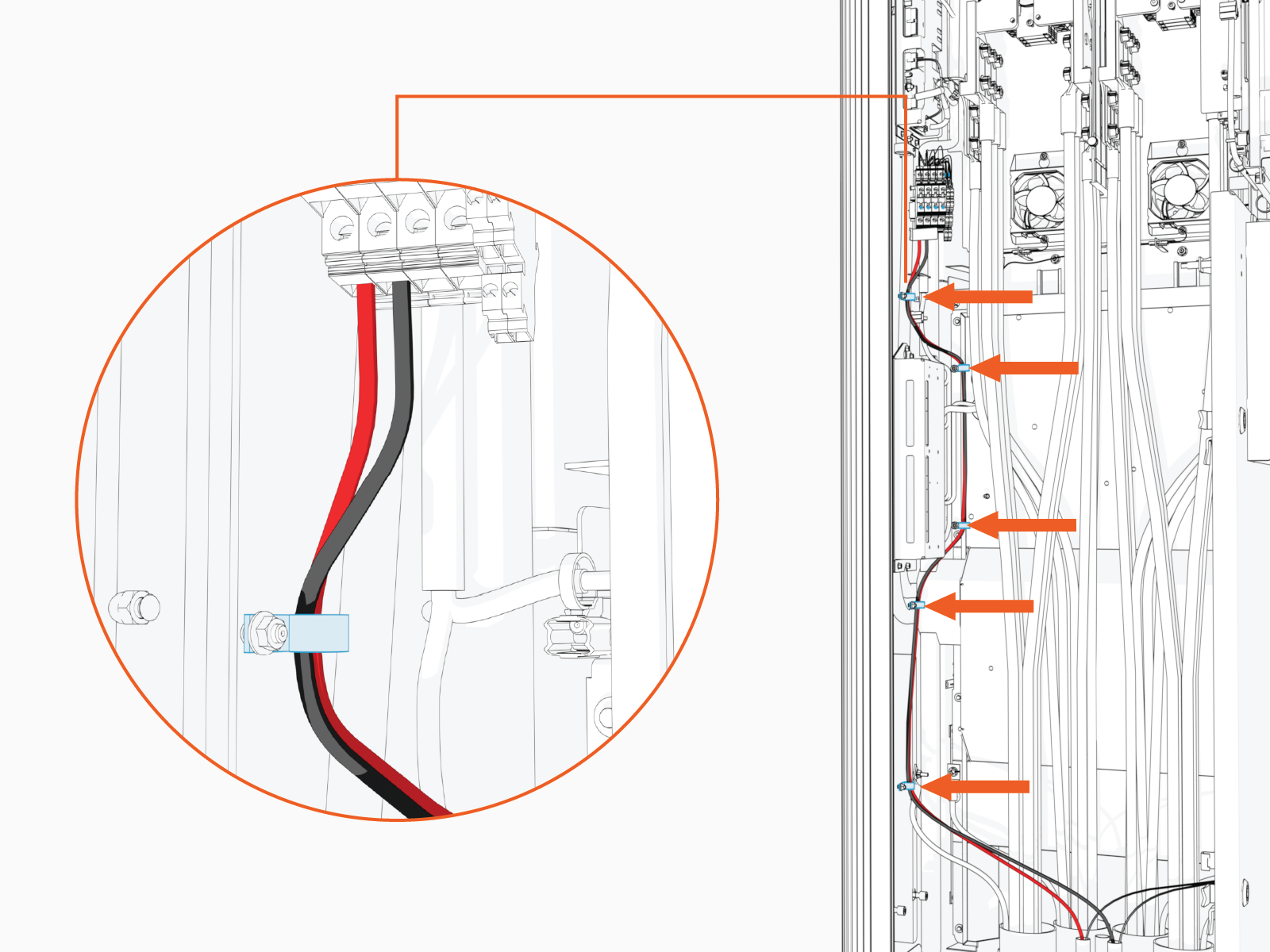
-
Torque the screws (x2) to 1.5 Nm (13.3 in-lb). Push-pull to test that both (+ and -) wires are secured.
Connect Ethernet Cables
Follow the procedure below to connect each Ethernet cable.
-
On the Smart Ethernet Switch, locate three ports for landing Ethernet cables. All ports are equivalent.
If the wire terminals do not appear as pictured here, you are using the wrong installation guide. See About This Guide for more information.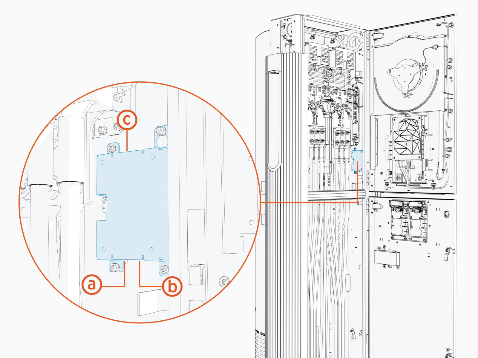
-
Lower left port
-
Lower right port
-
Upper port
-
-
Trim Ethernet (Cat6 STP
Shielded Twisted Pair) cable to length, allowing for a service loop. -
Field crimp a shielded RJ45 connector onto the Ethernet cable. Use straight-through T568B pattern.
Ground the Ethernet cable shield as follows:
-
For an Ethernet cable connecting from a power cabinet to Power Link 2000, ground the shield at the power cabinet cable end. Do not ground the shield at the Power Link 2000 cable end.
-
For an Ethernet cable connecting between Power Link 2000s, ground the shield at the cable end nearer to the power cabinet (per Ethernet topology for the Express cluster). Do not ground the shield at the other cable end.

-
-
Test the Ethernet cable for functionality.
If using a Paige OSP Shielded GameChanger cable for a wire run length greater than 100 m (328 ft), follow the test procedure specified by Paige. See Paige GameChanger Resources.

-
Route the cable through the wireway clamps and connect to any available port on the Smart Ethernet Switch. To establish a secure connection, the RJ45 connector's latch must click into the switch.