Install Charging Cables
Skip this entire chapter if the liquid-cooled cables come preinstalled (see Power Link 2000 with LCC).
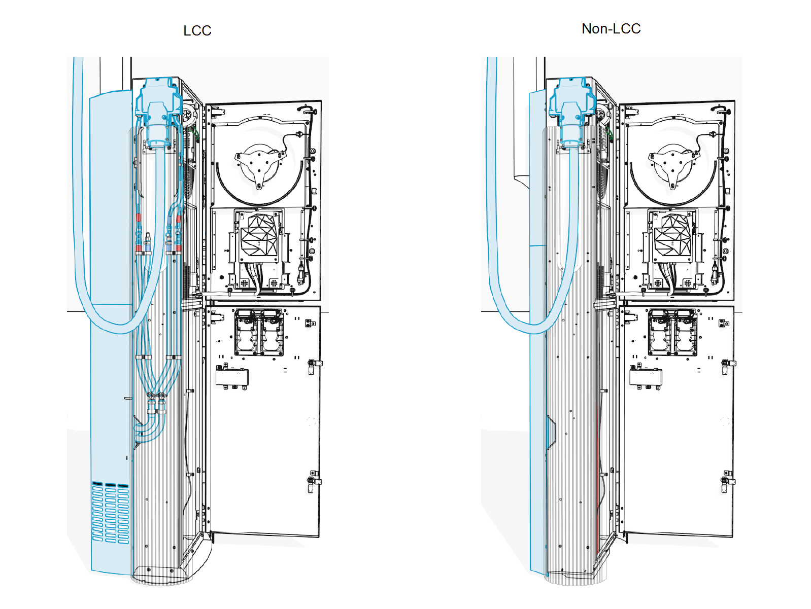
The Power Link 2000 may be configured with one or two liquid-cooled cables (LCC Liquid Cooled Cable) or non-liquid-cooled cables (non-LCC Liquid Cooled Cable). The Power Link 2000 with LCC Liquid Cooled Cable comes with a liquid cooling system attached to the back of the Power Link 2000 (see Charging Cable Type and Quantity for more information). To install charging cables, follow the instructions below:
Charging Cable Package
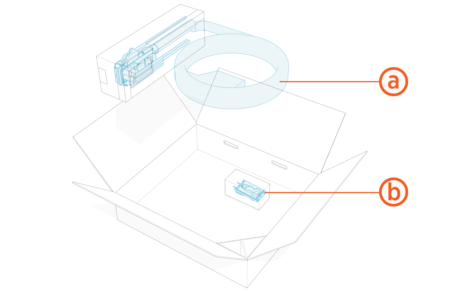
Check the package for the following components:
For any missing component, contact ChargePoint support at chargepoint.com/support.
-
Charging cable assembly with connector and tetherball
-
Holster for placing the cable connector
Standard length (5.8 m or 19 ft) charging cables come with a tetherball preinstalled onto the cable. For non-LCC Liquid Cooled Cable medium length (7.6 m or 25 ft) charging cables, a tetherball is not preinstalled onto the cable. It must be installed after installing the charging cable or while installing the CMK Cable Management Kit.
Remove Cable Cap
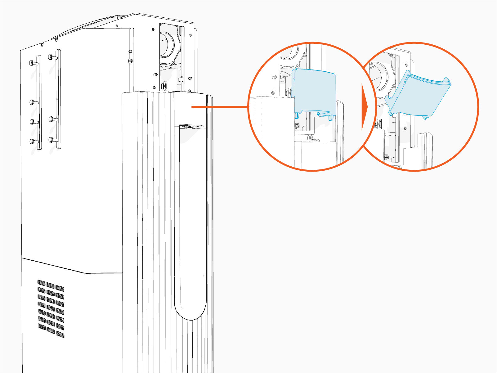
Pull the cable cap up to remove and keep it aside to reinstall it later.
Remove High-Power DC Lug Landing Bus Bar Safety Cover
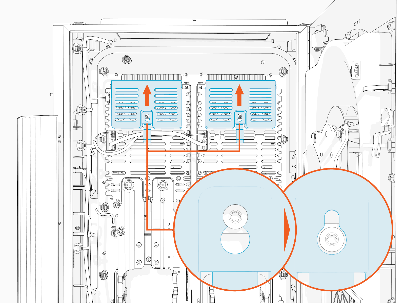
To remove high-power DC lug landing bus bar safety cover, complete the following steps:
-
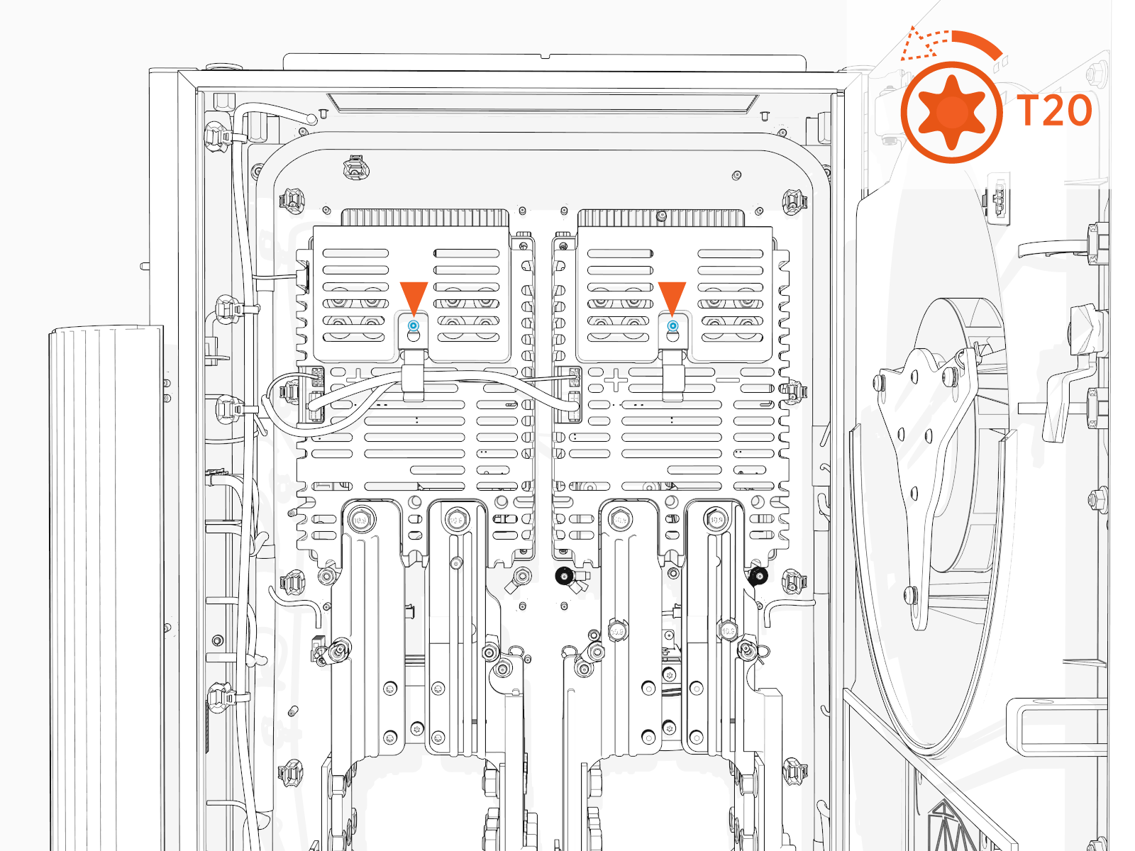
Loosen the screw (x1 per safety cover).
-
Slide the safety cover up to remove it from the screw.
Install Cable Assembly
Follow instructions below to install each charging cable assembly.
-
Route the red (+) and black (-) high-power DC wires through the Ferrite ring. Route other wires, such as ground (green) and Ethernet, outside of the Ferrite ring.
While routing the left side cable through the Ferrite ring, make sure that the red (+) wires are at the front side and black (-) wires are at the rear side to easily maneuver and land them onto their respective poles. Conversely, while routing the right side cable, make sure that the black (-) wires are at front side and red (+) wires are at the rear side.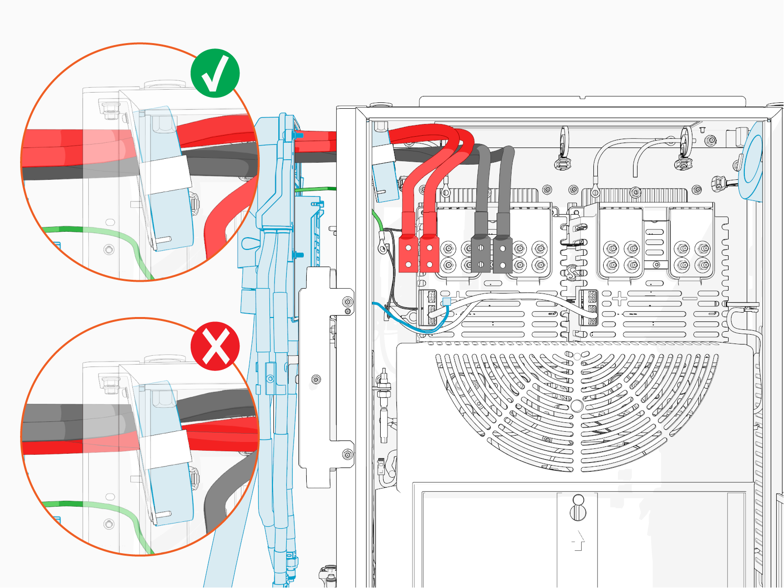
-
Install cable assembly onto the alignment pins (x2).
Ensure the small cables do not get pinched between the cable assembly and the Power Link 2000 frame.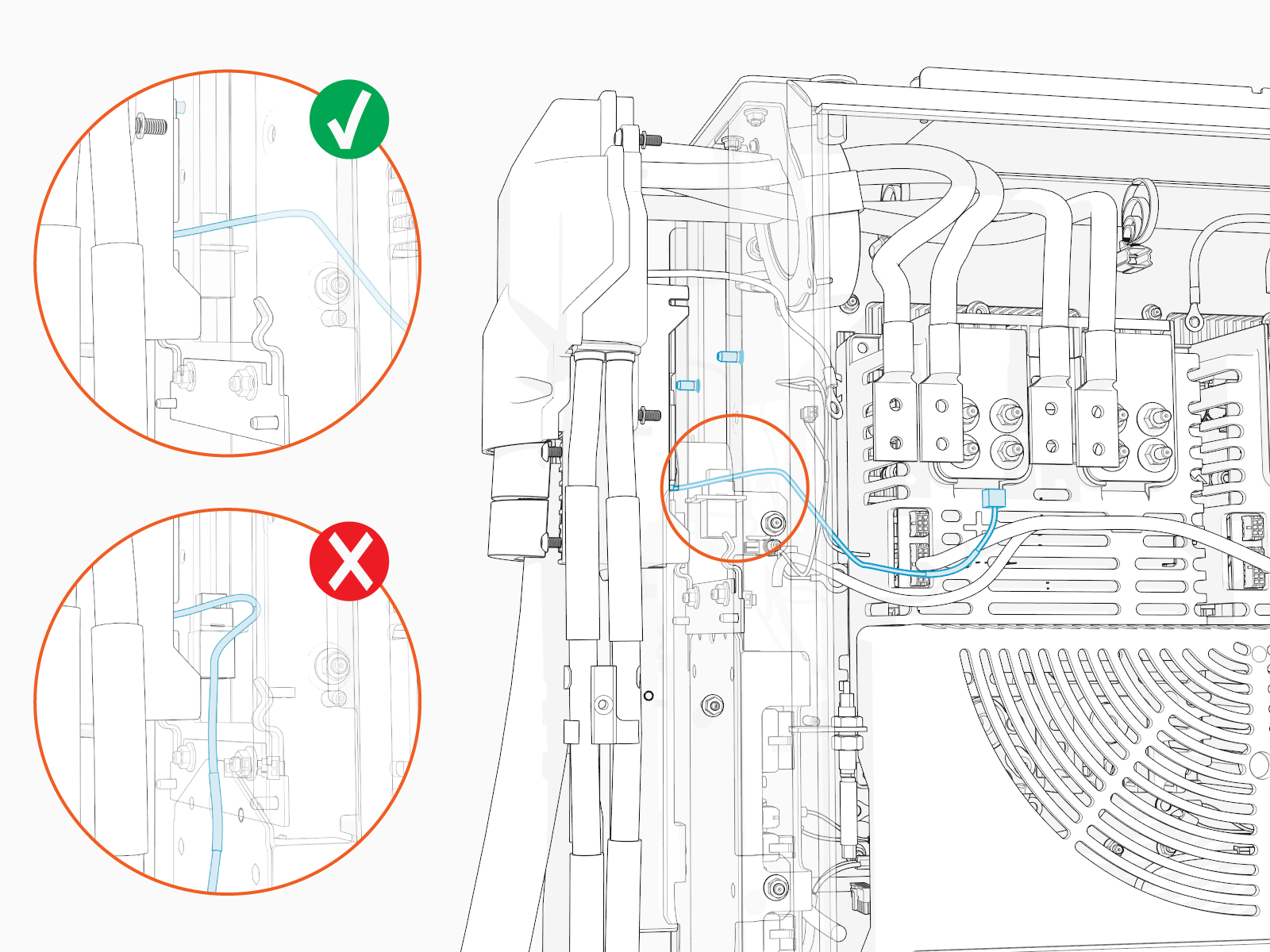
-
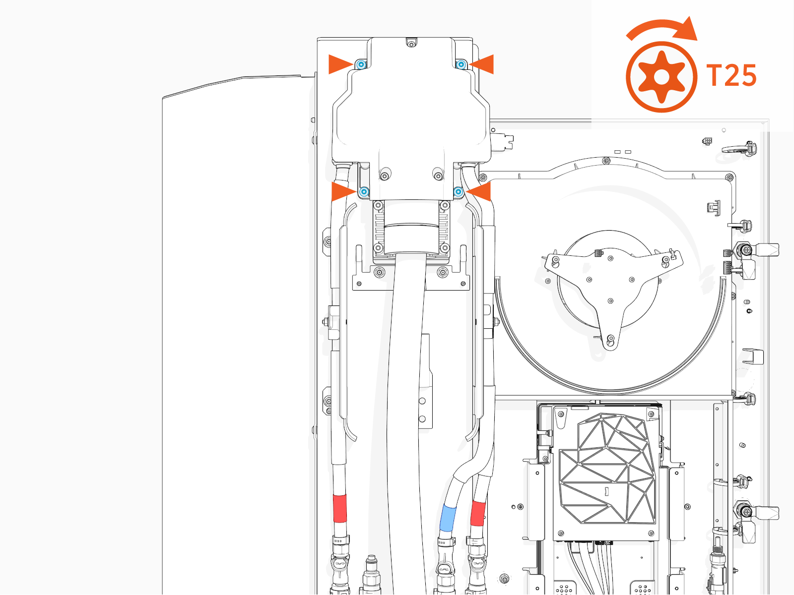
Torque the screws (x4) to 4.5 Nm (40 in-lb).
Connect High-Power DC and Ground Wires
Complete the following steps to connect the charging cable high-power DC wires and ground wires.
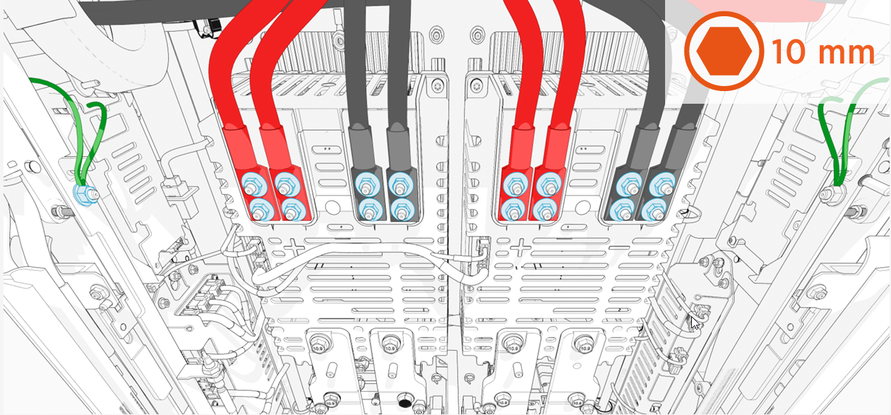
In the illustration below, the high-power DC conductors from the left charging cable land on the left Proton, and the high-power DC conductors from the right charging cable land on the right Proton.
|
|
-
Remove the lug nuts (x4 per red and black high power DC wires; x1 per green ground wire).
-
Connect red high-power DC wire conductors to the positive (+) landings and black high-power DC conductors to the negative (-) landings.
-
Connect green ground wires (x2 per charging cable) to ground studs on the frame.
-
Torque all lug nuts to 5.6 Nm (50 in-lb) and mark using a torque paint pen.
Connect 48 V DC and Ethernet Wires
Complete the following steps to connect the charging cable 48 V DC and Ethernet wires.

-
Plug in the 48 V DC wires (with labels P317-2-06 and P317-1-06) to four pin socket on the cable assembly.
-
Plug in the Ethernet cable from the charging cable assembly, as illustrated above.
Reinstall High-Power DC Lug Landing Bus Bar Safety Cover
To reinstall the high-power DC lug landing bus bar safety cover, complete the following steps:
-
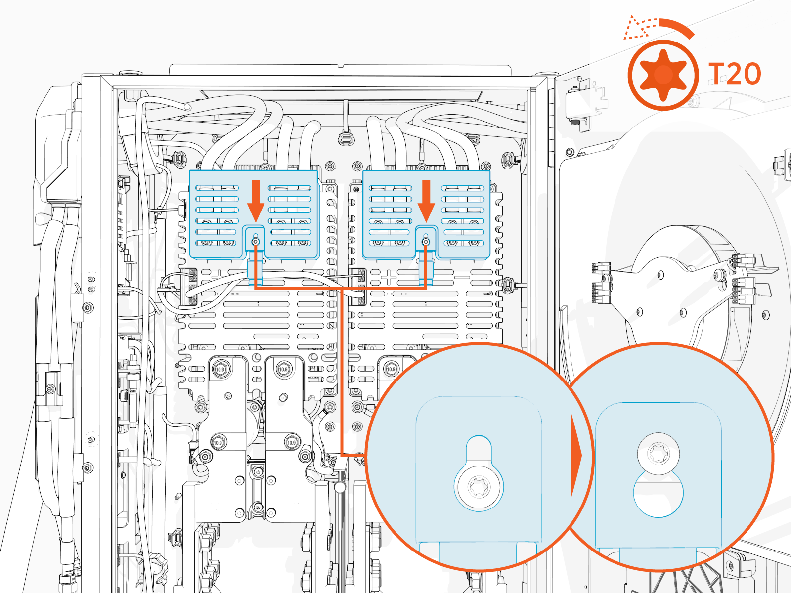
Install the safety cover onto the screw (ensure that the screw is loose) and slide it down.
-
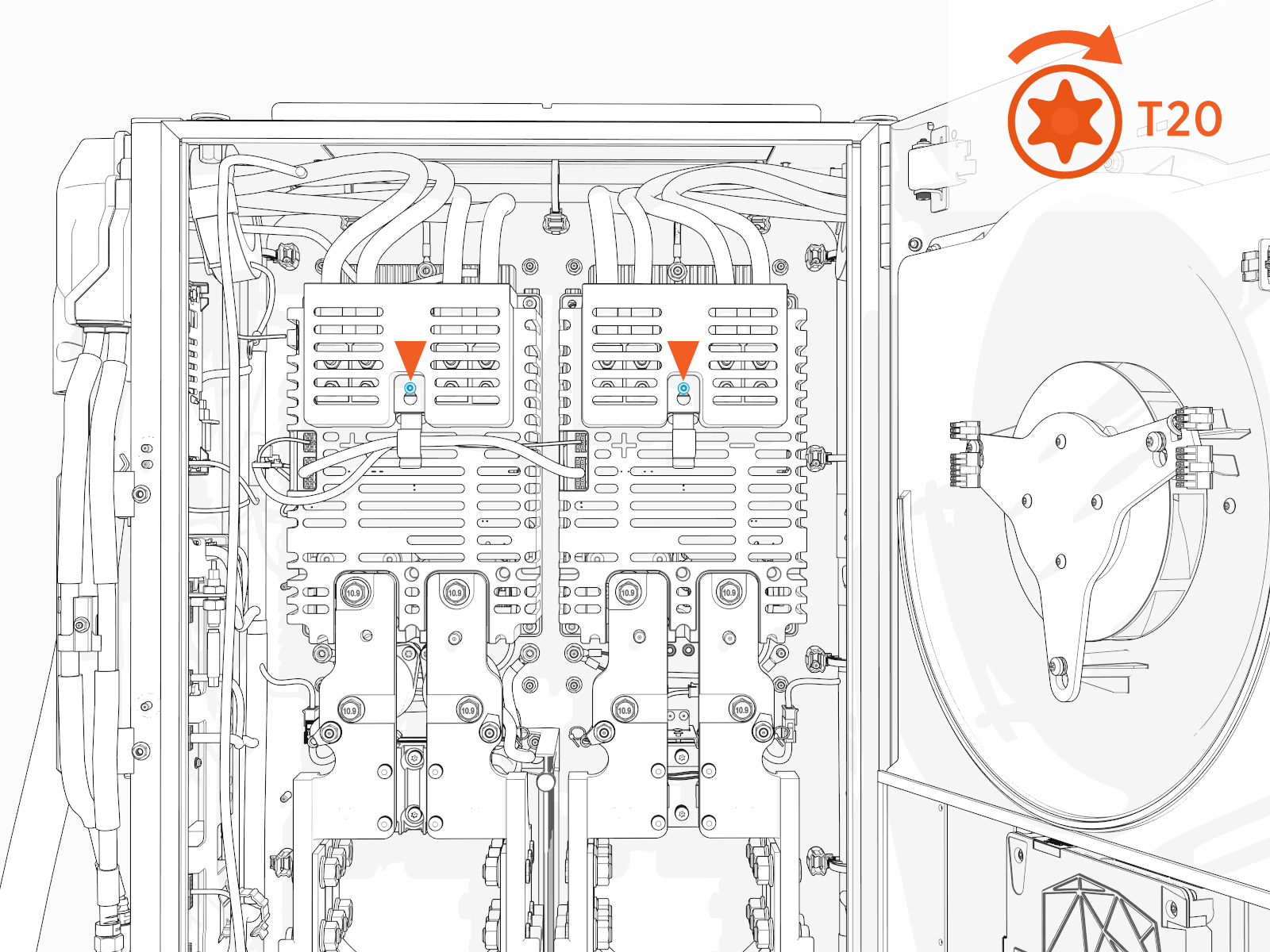
Torque the screw to 1.7 Nm (15 in-lb).
-
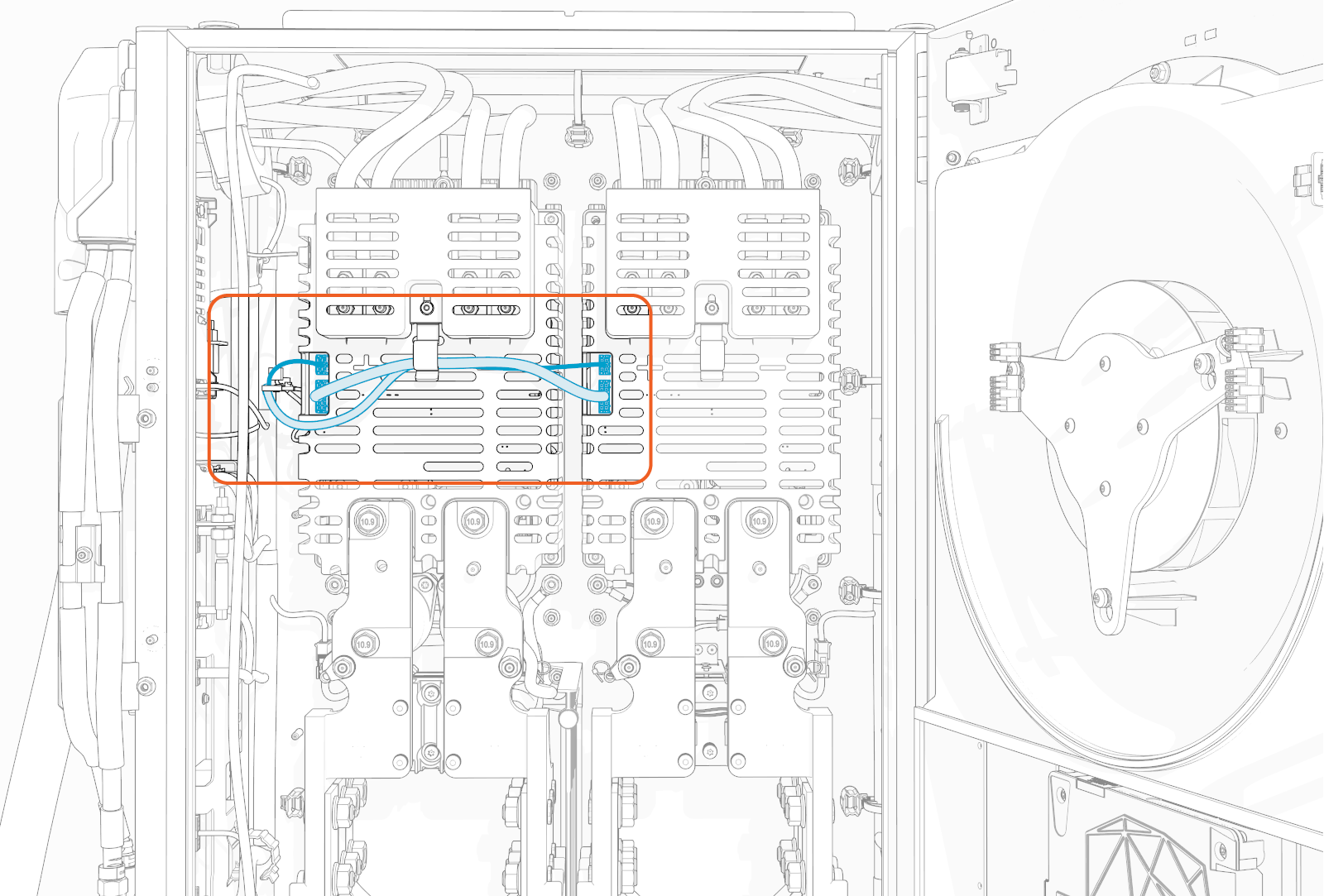
Tuck the internal low voltage supply wires under the wireway tab on the cover.
Install Holsters
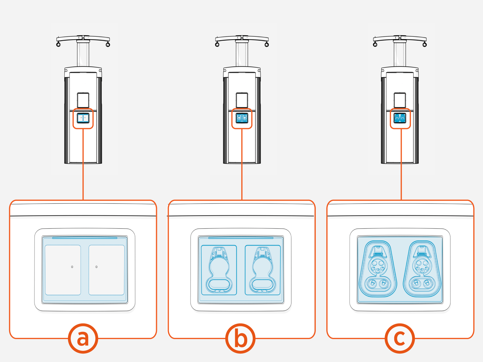
Power Link 2000 can be configured with standard holsters or Omni Port. A newly shipped Power Link 2000 shall arrive in one of the following configurations:
-
With a holster bracket preinstalled (standard holsters must be field-installed into the bracket)
-
With standard holsters and holster bracket preinstalled
-
With Omni Port preinstalled
Install Standard Holsters
If the Power Link 2000 requires standard holsters but did not ship with them preinstalled, follow
instructions in this section to install holsters.
-
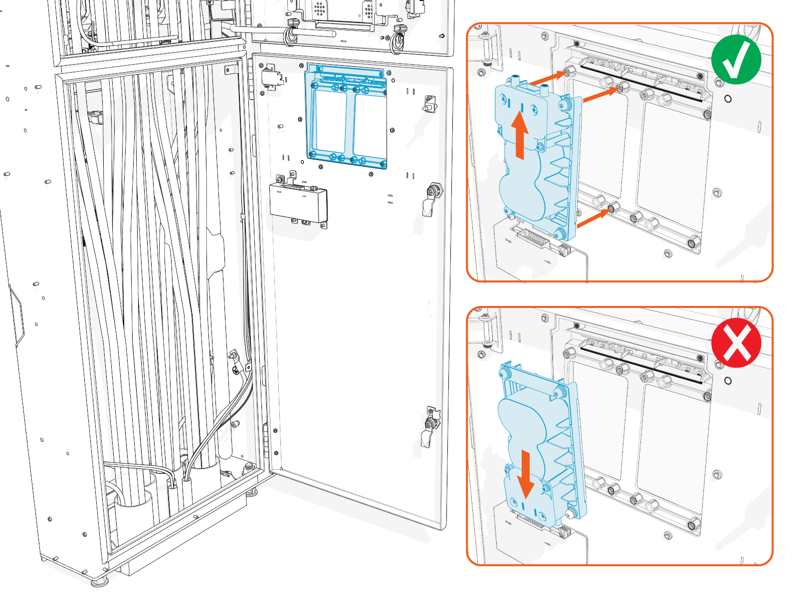
Find the holster shipped with the charging cable.
-
Align and seat the holster onto the holster bracket.
-
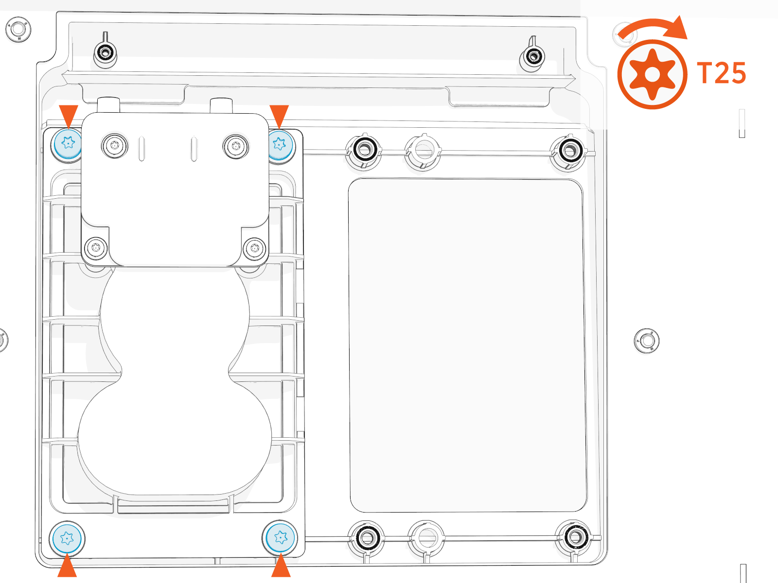
Torque the screws (x4) to 2.8 Nm (25 in-lb).
-
If the Power Link 2000 is configured with two charging cables, repeat the above procedure to install a second holster.
Install Omni Port
If the Power Link 2000 requires configuration with Omni Port but did not ship with one preinstalled, follow instructions in this section to install the Omni Port.
Mount Omni Port
-
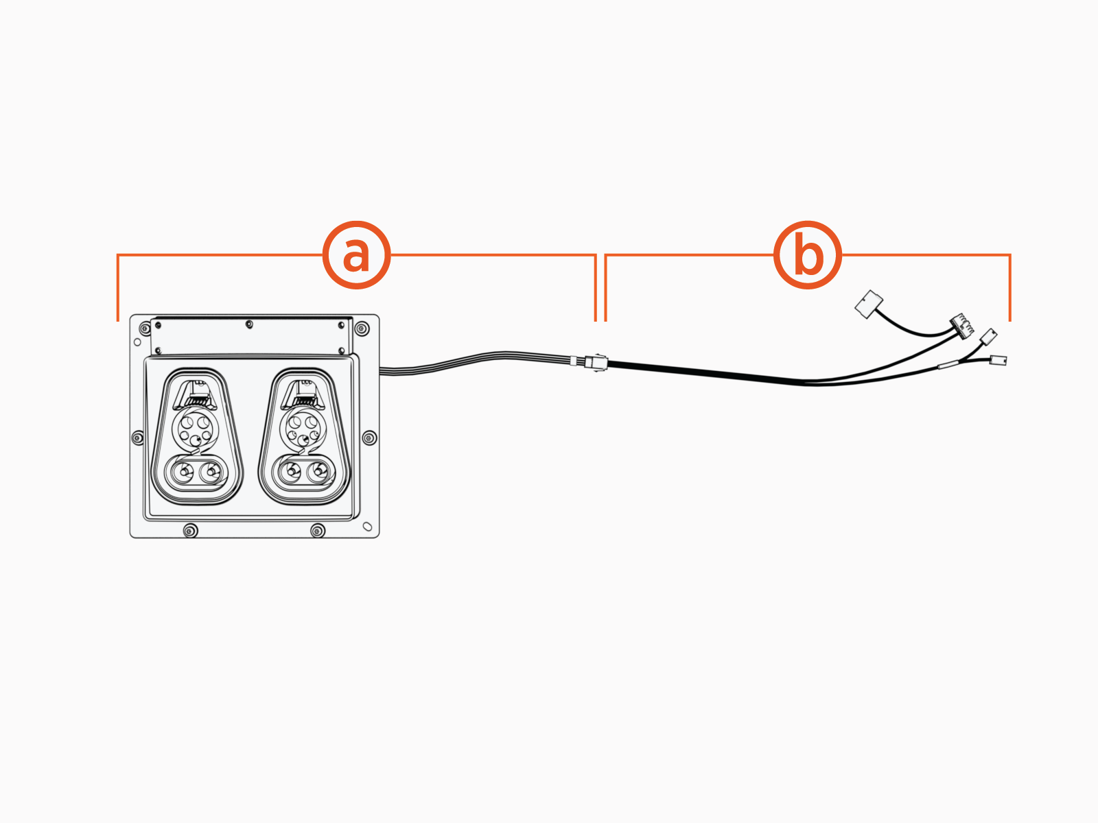
Unpack the Omni Port package. Confirm all parts listed below are present.
-
Omni Port assembly with cable
-
Pigtail cable
For any missing component, contact chargepoint.com/support.
-
If the Power Link 2000 shipped with a standard holster bracket preinstalled, remove screws (x6) and remove the holster bracket.
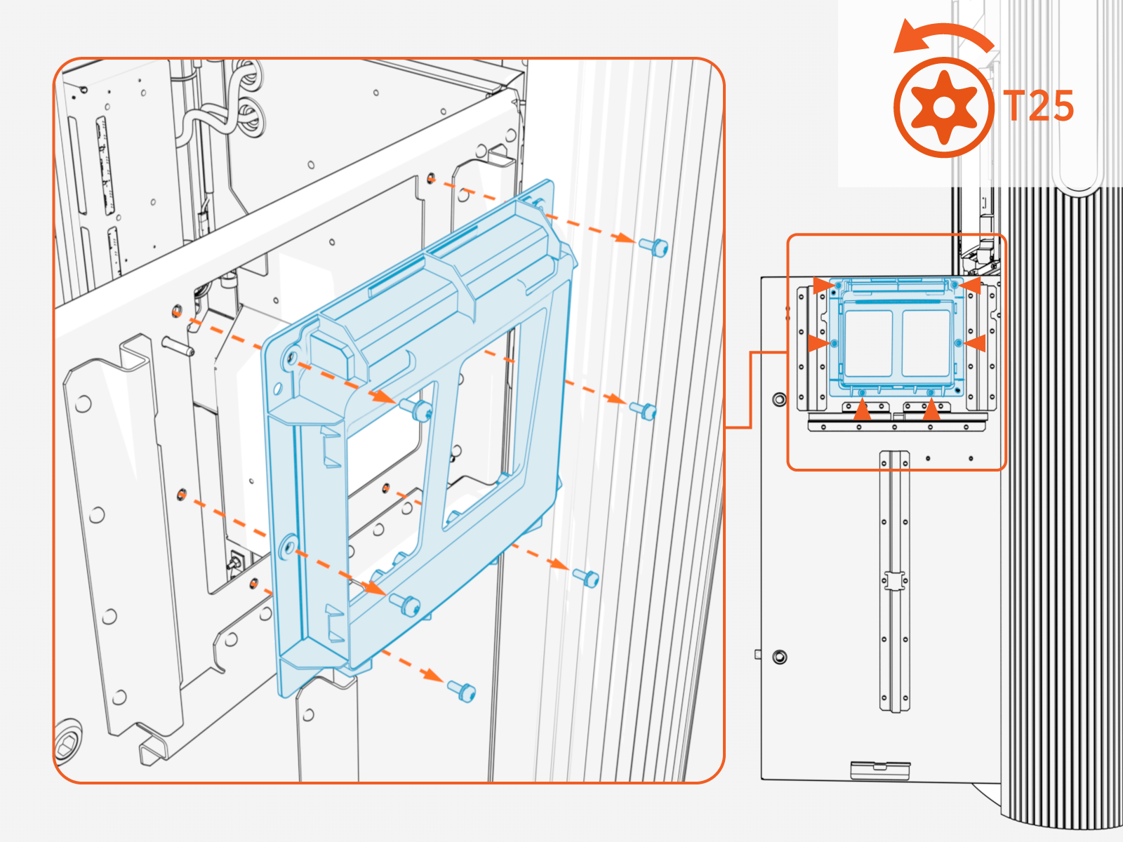
-
Align and seat the Omni Port assembly into the holster opening.
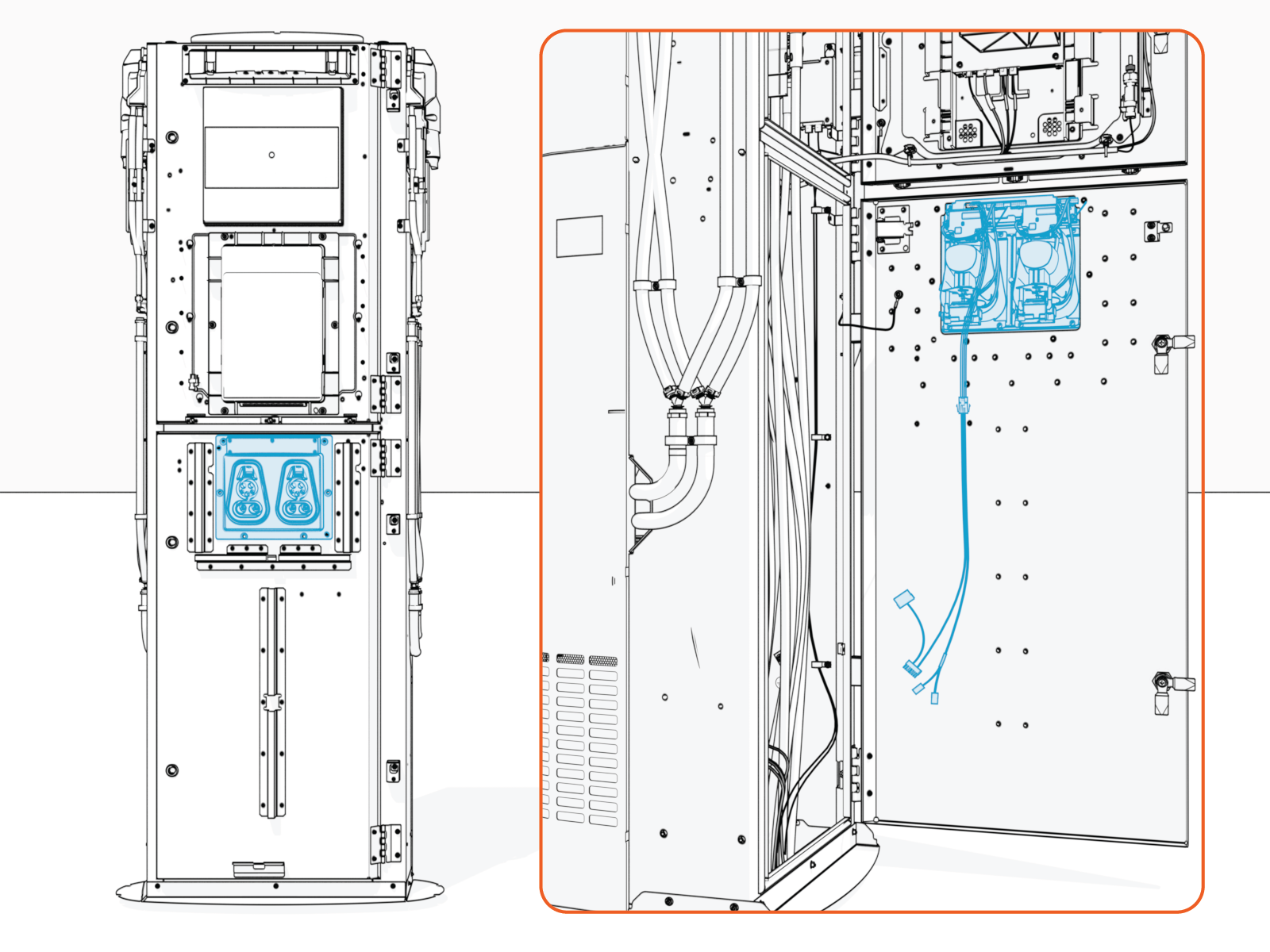
-
Install screws (x6). Torque to 4.5 Nm (40 in-lb).
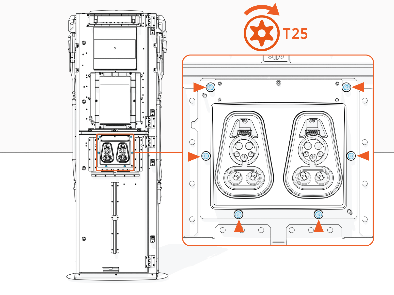
Connect Omni Port wires
To connect Omni Port wires, complete the following steps:
-
Disconnect and remove the Omni Port pigtail cable. The pigtail cable is not needed.
-
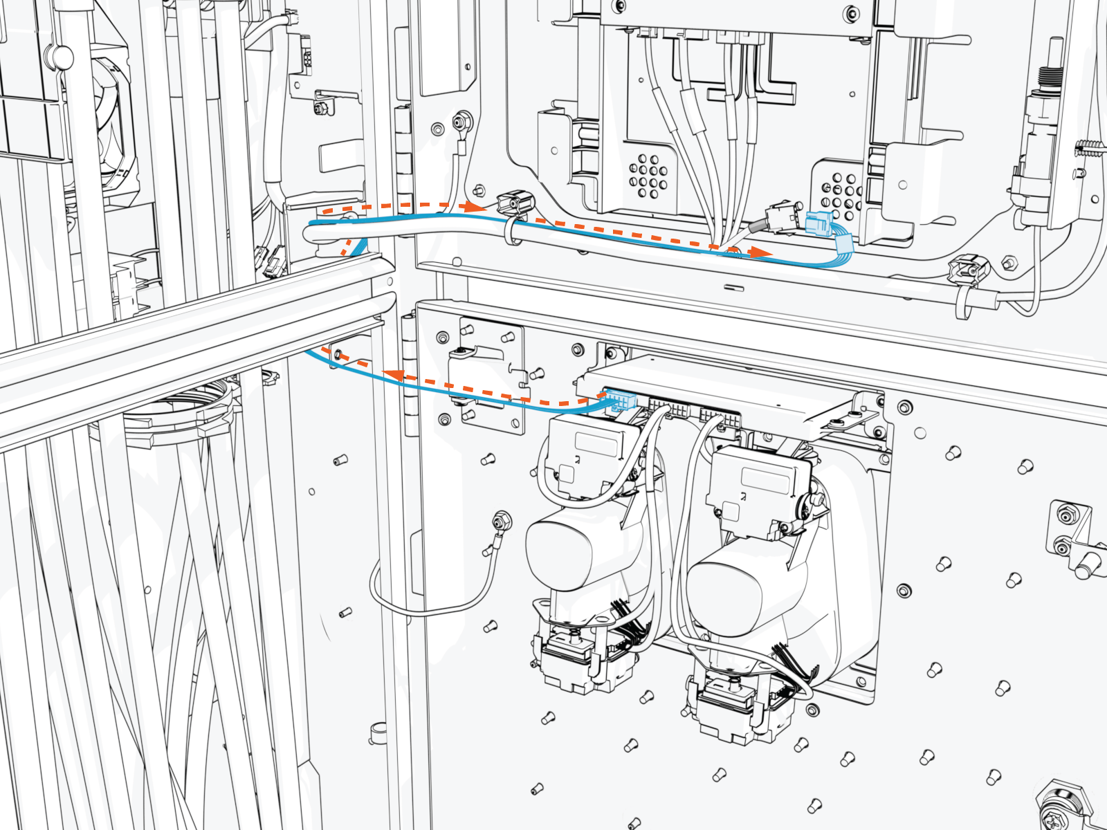
Route the Omni Port cable harness to reach the main cable harness on the Power Link 2000 door.
The cable harness must route behind the mid-height brace and through the door cable guide to prevent the cable from being pinched when closing the door.
-
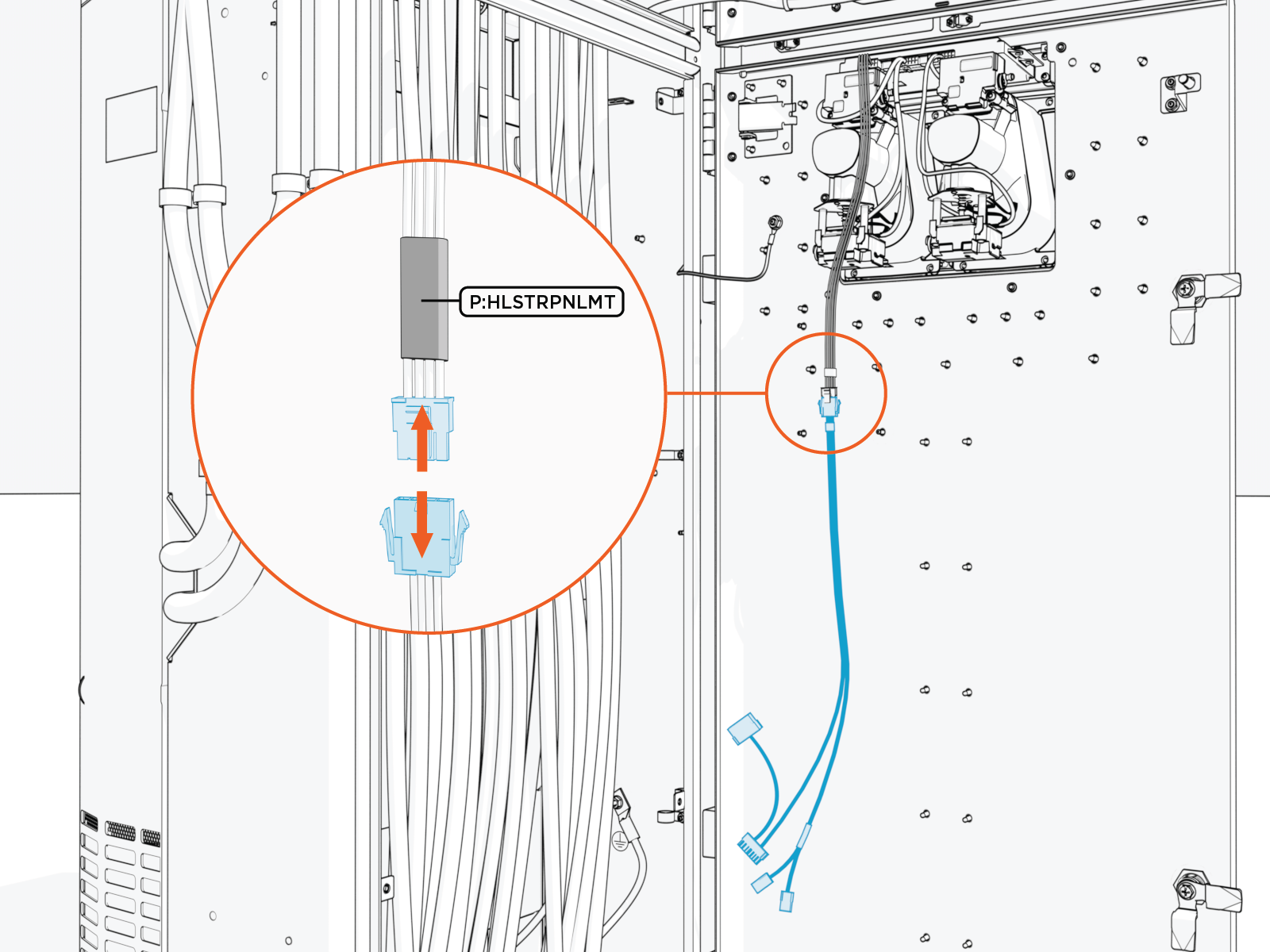
Connect the Omni Port cable harness to the main cable harness.
The cables are labeled as shown below. The latch must snap onto the receptacle connector with a click to ensure the connection is secure.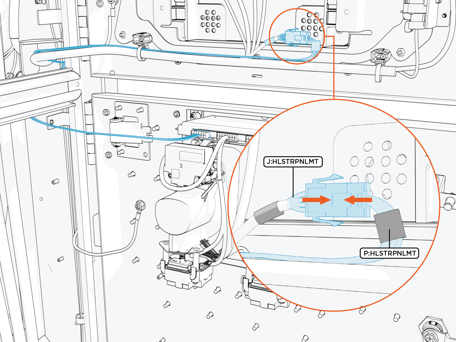
-
Use zip ties to secure the Omni Port cables to the main cable harness.
Pull excess cable into the Power Link 2000 pedestal to ensure there is no loose wire hanging from the door. Loose wires may get pinched when closing the door.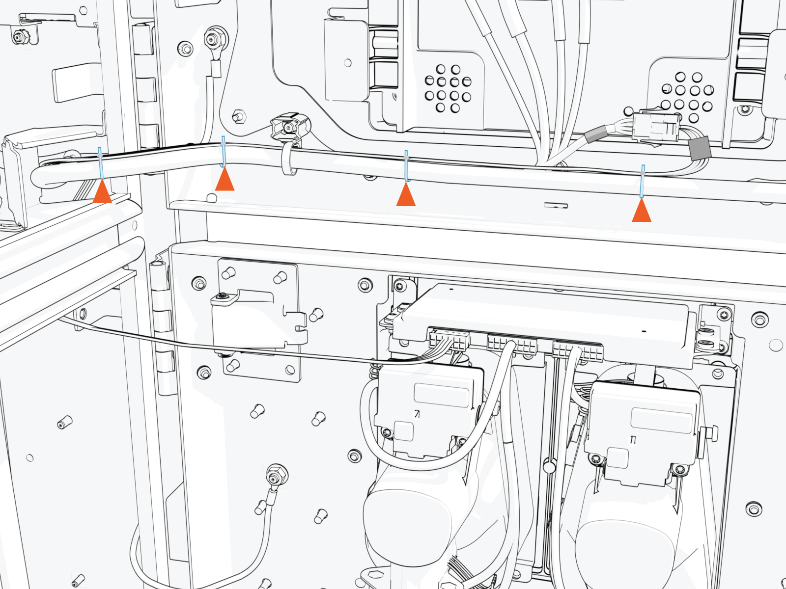
-
Check that the lower door can close properly.
The rear side of the Omni Port should not touch the DC power path wires within the Power Link 2000 pedestal when the door is closed. If needed, adjust the DC power path wires to avoid such contact.
