Civil and Mechanical Design
This section provides civil and mechanical site design information for Power Hub.
Component Dimensions and Weight
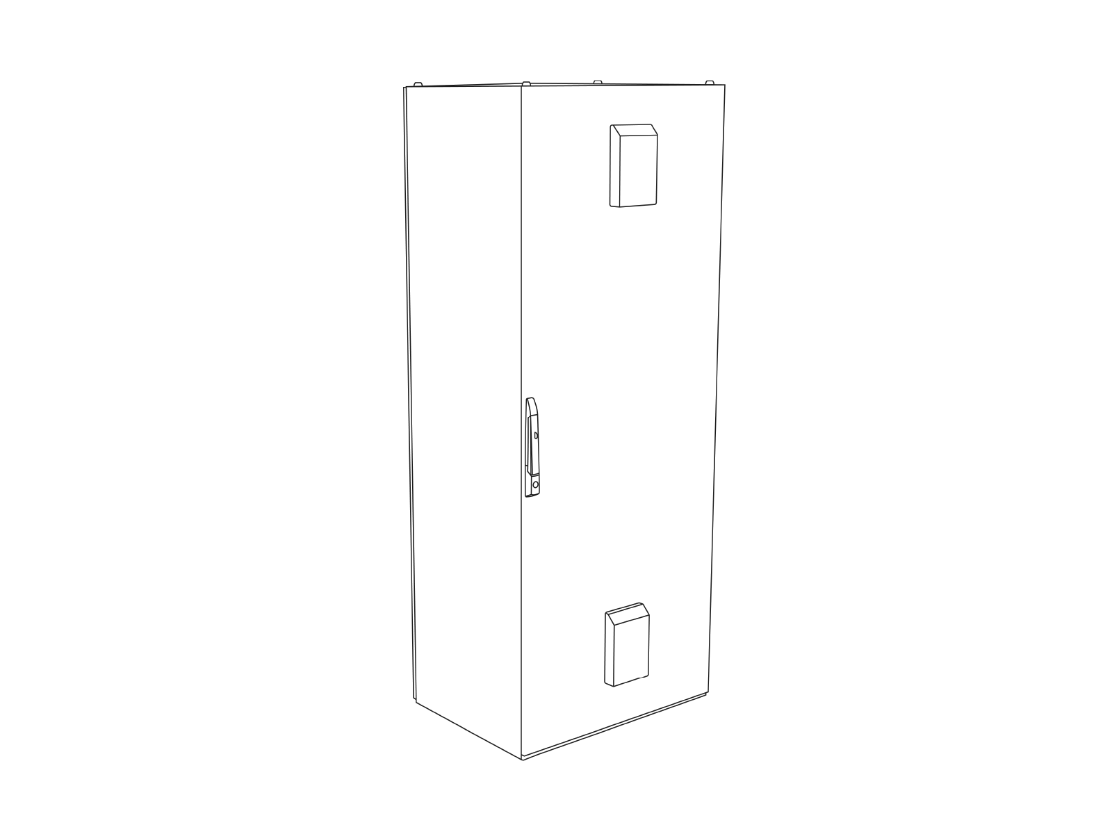
The Power Hub is a vertical enclosure with the following dimensions and weight:
|
Generic Specifications |
|
|---|---|
|
Cabinet Height (H) |
2.006 m (79 in) |
|
Cabinet Width (W) |
800 mm (31-1/2 in) |
|
Cabinet Depth (D) |
605 mm (23-3/4 in) |
|
Cabinet Weight (as shipped) |
181 kg (400 lb) |
Mounting Specifications for Pads
The Power Hub is secured to a concrete pad using four embedded anchor bolts. The Power Hub can be installed on either a newly poured concrete pad or an existing concrete surface. Its input and output cables can run under the grade surface in trenches, protected by conduits, and enter the cabinet through its base. Alternatively, the cables can be run along the grade surface, protected by wireways, and enter the cabinet through its side or rear walls.
The Power Hub concrete mounting surface must be smooth and cannot exceed a slope of 20 mm per meter (0.25 inches per foot).
Pad Stability Specifications
Conservative stability specifications for the Power Hub are listed below for the following design scenarios:
-
170mph wind, high seismic, Class 3 Soil
-
170mph wind, high seismic, Class 4 Soil
-
170mph wind, high seismic, Class 5 Soil
-
140mph wind, lower seismic, Class 3 Soil
-
140mph wind, lower seismic, Class 4 Soil
-
140mph wind, lower seismic, Class 5 Soil
All scenarios assume:
-
Minimum concrete rating of 4,000 PSI
-
An anchor bolt embedment of 102 mm (4 in) using 5/8 in diameter HILTI HAS-R 316 SS all-threaded anchor rod, epoxied with HIT-HY-200
-
305 mm (12 in) mechanically compacted granular fill subgrade beneath the pad
-
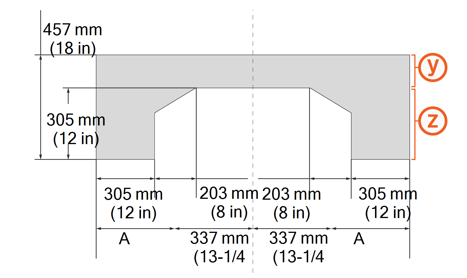
#4 rebar @ 305 mm (12 in) O.C. centered in top surface of slab with standard ACI 90o hook at ends of bars (see (y) in diagram below)
-
#3 stirrup rebar @ 610 mm (24 in) O.C. maximum in perimeter base of slab (see (z) in diagram below)
-
#4 rebar @ 305 mm (12 in) O.C. T&B within corners of rebar stirrups in perimeter base of slab
Conservative pad dimensions:
|
Design Scenario |
Dimension A |
Dimension B |
|---|---|---|
|
1 |
806 mm (2 ft 7-3/4 in) |
902 mm (2 ft 11-1/2 in) |
|
2 |
806 mm (2 ft 7-3/4 in) |
902 mm (2 ft 11-1/2 in) |
|
3 |
806 mm (2 ft 7-3/4 in) |
902 mm (2 ft 11-1/2 in) |
|
4 |
654 mm (2 ft 1-3/4 in) |
749 mm (2 ft 5-1/2 in) |
|
5 |
654 mm (2 ft 1-3/4 in) |
749 mm (2 ft 5-1/2 in) |
|
6 |
654 mm (2 ft 1-3/4 in) |
749 mm (2 ft 5-1/2 in) |
The Power Hub must be centered within the designed stability area.
The concrete pad for the Power Hub must either be designed to be site-specific or must meet the specifications above. In some extreme conditions, a larger pad would be required. For sites with less stringent seismic, soil, or wind conditions, a smaller pad might be possible.
If using an existing pad that does not meet the specifications above, the pad must be inspected and approved by a structural engineer for each component’s dimensions and weight. If needed, give these structural design specifications to the structural engineer for verification:
|
Product Weight |
181 kg (400 lb) |
|
Product Height from Ground |
2.006 m (79 in) |
|
Product Width |
800 mm (31-1/2 in) |
|
Product Frontal Area |
Height * Width |
|
CG Height |
918 mm (36-5/32 in) |
|
Number of Anchor Bolts |
4 |
|
Bolt Pattern |
|
|
Anchor Bolt Size and Type |
5/8 in diameter HILTI HAS-R 316 SS all-threaded rod |
|
Anchor Bolt Embedment |
102 mm (4 in) |
If an existing pad does not meet the site specific specifications determined by a civil engineering analysis, it must be inspected and approved by a structural engineer based on the parameters above.
Concrete Pad Mount
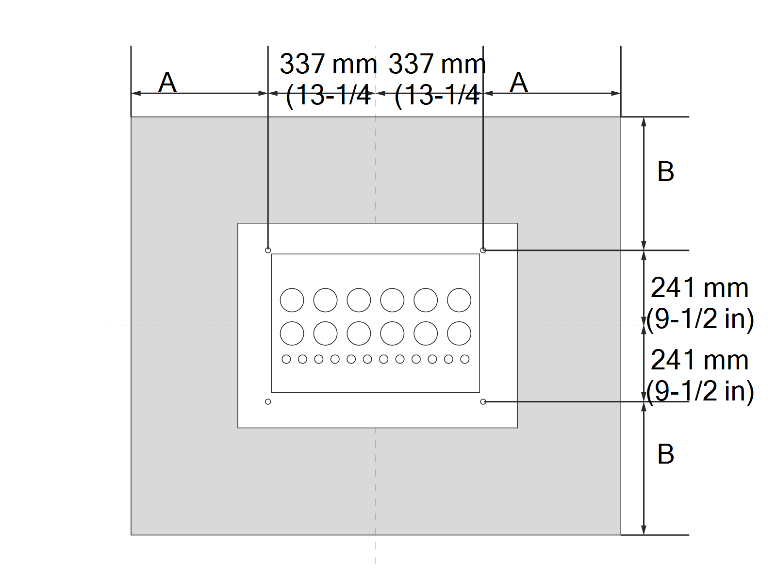
The Power Hub is secured to a concrete pad using four embedded anchor bolts, positioned as shown below in a top-down view.
-
Power Hub cabinet footprint
-
5/8 inches embedded anchor bolts (x4) with 38 mm (1-1/2 in) length exposed above concrete
-
Cabinet rear side
The anchor bolts will slot into 20 mm (13/16 in) diameter bolt holes at the base of the Power Hub cabinet. Design for appropriate tolerance in the placement of the anchor bolts.
Stub-up Conduit Entry
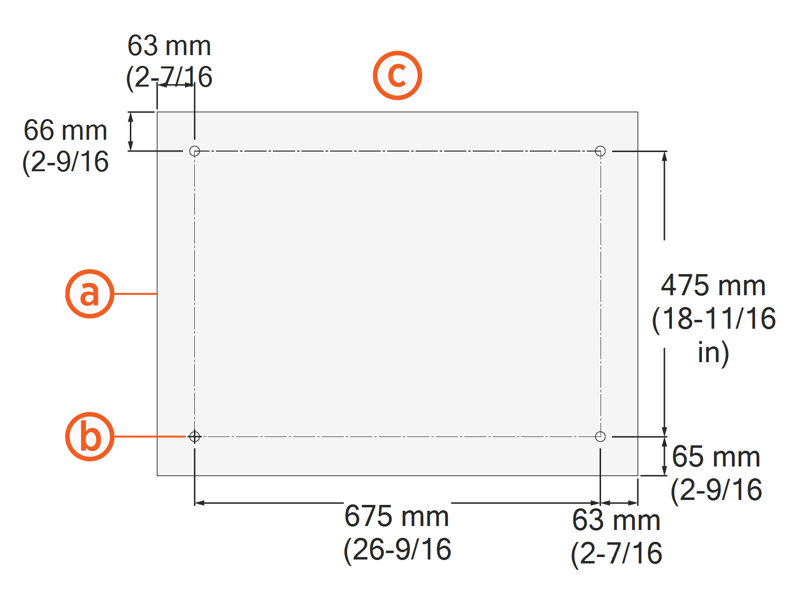
A new pad installation with stub-up conduit entry through the cabinet floor is the most common mounting method for the Power Hub. A top-down view of the conduit stub-up and cable entry location is shown below.
See Appendix: Wire Landing Locations. A gland plate that covers the opening may be equipped with conduit fittings.
-
Power Hub cabinet footprint
-
Floor opening for conduit and wire entry
-
Conduits
-
Cabinet rear side
Riser Kit
A Riser Kit is available for installations requiring additional space beneath the Power Hub cabinet for conduit fittings or cable glands. The Riser Kit raises the Power Hub cabinet by 100 mm (4 in).

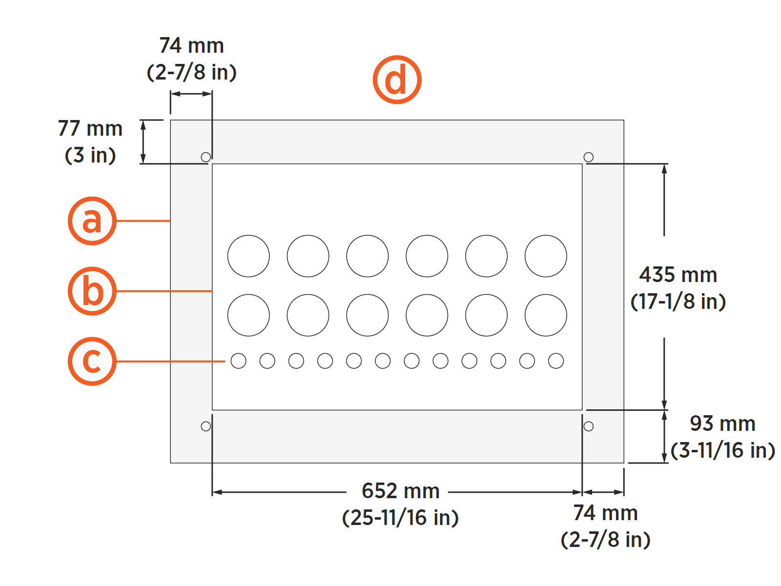
Surface Conduit Entry
Power Hub supports wiring that is run above ground in protected wireways, for locations where no underground wiring access exists (parking garages, etc.). Surface wires may enter at the rear (a) or sides (b) of the cabinet, within the areas indicated below. Wires may be arranged in any position within the allowed area, and the cabinet wall may be equipped with conduit fittings.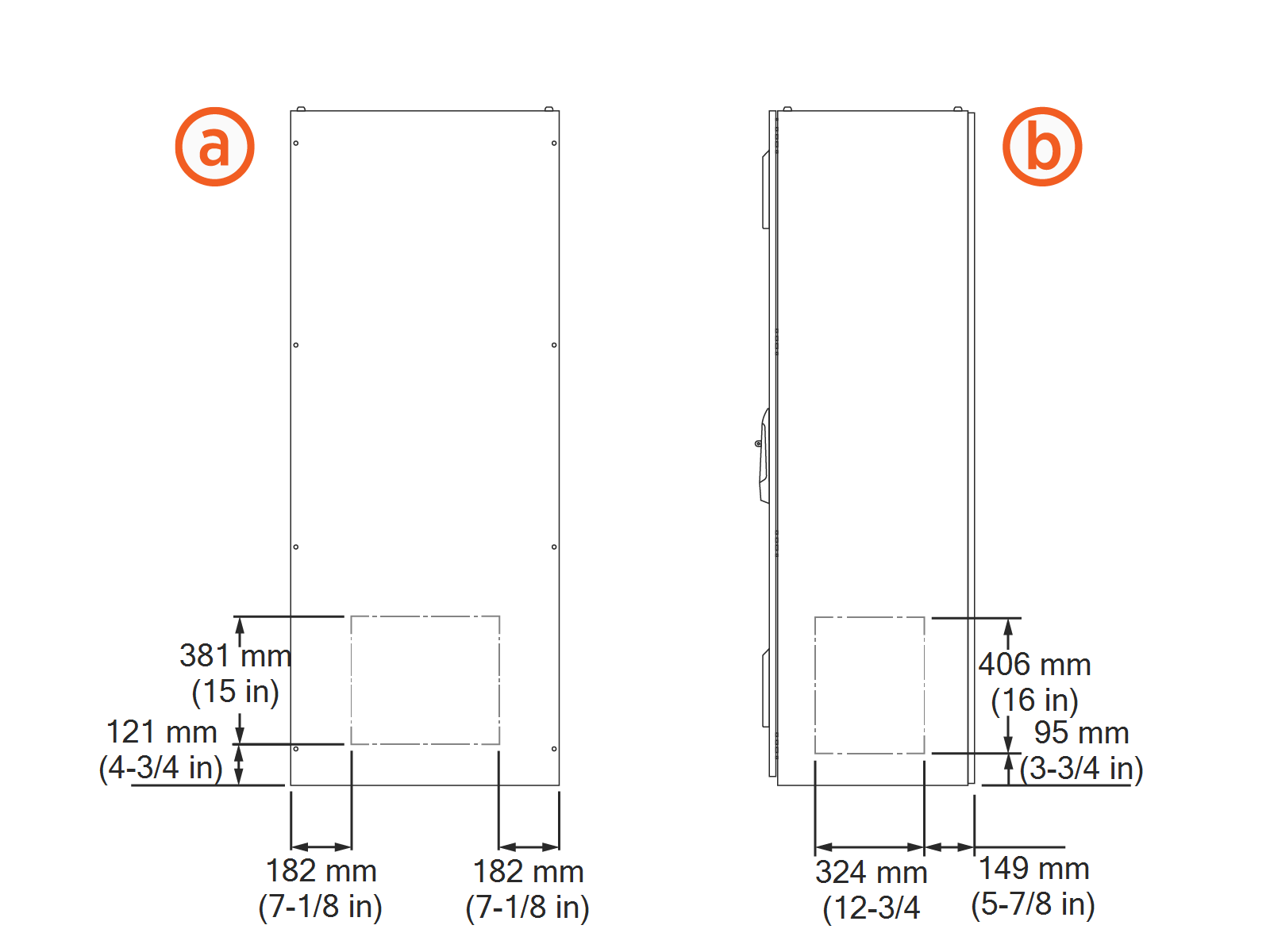
If cables are run above grade, they must be housed in wireways that conform to local code. Select a surface conduit entry solution that:
Supports the weight of conduits and components without compromising panel integrity
Ensures all terminations meet ingress requirements where they meet the component
To prepare the site for above grade wiring:
Ensure the plans for the concrete pad and access area allow full service access to all components. Surface conduit entry might require larger clearance areas than underground conduit entry installations.
Prepare the concrete surface where the components will be anchored so that the concrete is solid and smooth, with no old hardware or stub-ups extending above grade.
Drainage
Ensure any site slopes, walls, or fencing do not trap water around the cabinet installation site.
Exposing the Power Block to over 457 mm (18 in) of standing water could create an electrocution, shock, or fire hazard.
If the Power Block has been exposed to standing water exceeding this threshold, cut power to the Power Block and contact ChargePoint before powering on the Power Block.
Clearances
A Power Hub configured for surface conduit entry may require additional clearance at any side of the cabinet hosting conduit entry. Allow sufficient space for cable bend and pull.
For any questions about allowable layouts, contact ChargePoint.
![]()
Front and rear clearances are maintained
At least 457 mm (18 in) of clearance exists at each end of a row of Power Blocks and Power Hubs
Access to the back of each Power Block exists for maintenance
Side clearances can be shared between Power Blocks and Power Hubs as long as:
Front and rear clearances must be at grade level +/- 13 mm (1/2 in).
A Power Hub configured for stub-up conduit entry requires minimum site and service clearances listed below.
![]()
(a) Front: 792 mm (31-1/4 in) required
(b) Right side: 51 mm (2 in) required
(c) Left side: 51 mm (2 in) required
(d) Rear: 51 mm (2 in) required
Accessibility
Comply with regional accessibility laws, regulations, and ordinances. The Power Hub must not block ramps or pathways.
