Electrical Design
This section provides electrical site design specifications for the Power Hub.
Input and Output Line Diagrams
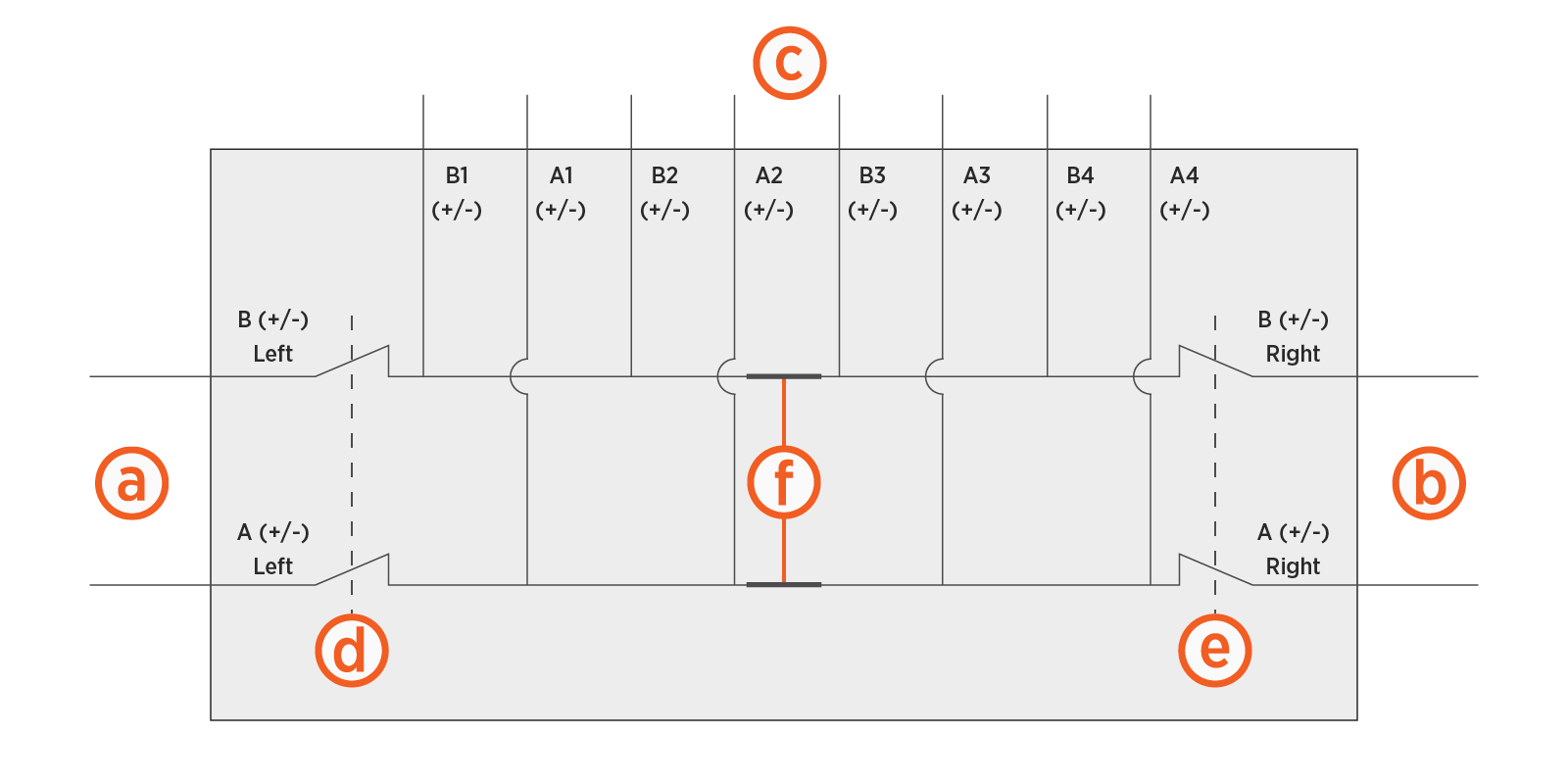
The Power Hub is configured with two high voltage buses with the following elements:
-
Two left side high voltage DC inputs
-
Two right side high voltage DC inputs (optional)
-
Eight high voltage DC outputs that connect to Power Link 1000s
-
One high voltage DC output per single input Power Link 1000, or
-
Two high voltage DC outputs per dual input Power Link 1000
-
-
Left disconnect switch
-
Right disconnect switch
-
Removable bus jumpers
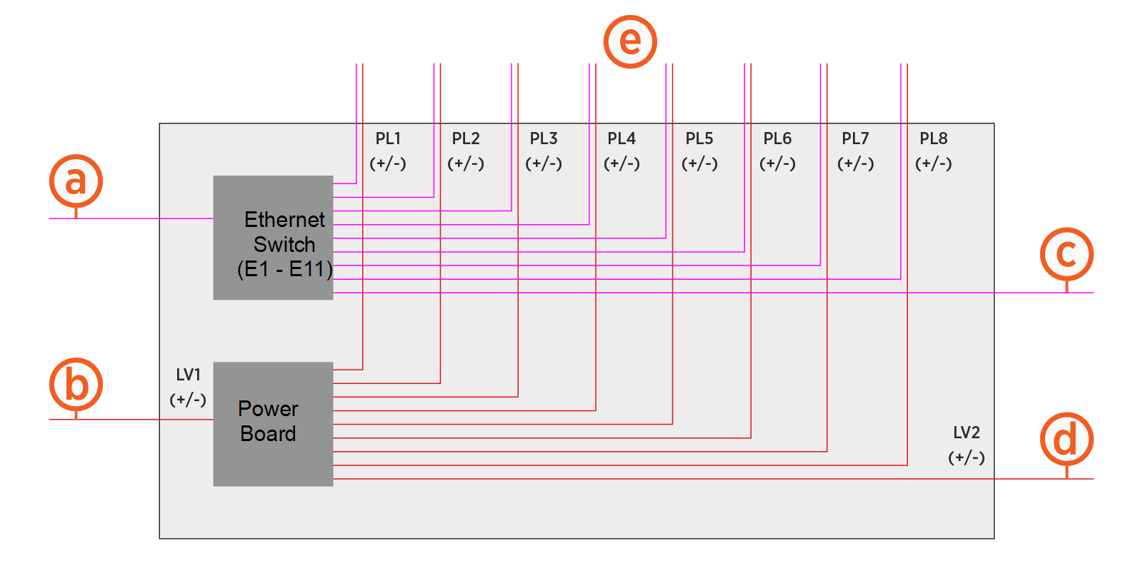
The Power Hub is configured for the following 48 V DC and Ethernet inputs and outputs:
-
One left side Ethernet input
-
One left side 48 V DC input
-
One right side Ethernet input
-
One right side 48 V DC input
-
Eight pairs of 48 V DC and Ethernet outputs
Grounding Requirements
Different charging components must be bonded to one another in sequence: Power Block to Power Hub to Power Link 1000s. The Power Block must be connected to a grounded, metal, permanent wiring system. An equipment-grounding conductor must be run with circuit conductors and connected to an equipment-grounding terminal or lead on the Power Hub.
Some regions also require a grounding rod to be installed adjacent to each component. Check local code to ensure compliance.
Disconnect Switch and Second Input Kit
The disconnect switch provides high voltage DC shutoff between a Power Hub and its input Power Block. This functionality improves system up-time during maintenance, as it allows servicing of the Power Link 1000s without powering off the Power Blocks.
The Power Hub ships equipped for high voltage DC inputs from one Power Block, denoted Power Block Left. This default configuration includes hardware for landing high voltage DC cables from Power Block Left, and a disconnect switch for high voltage DC power shutoff from Power Block Left.
The Power Hub can be configured to accept high voltage inputs from a second Power Block, denoted Power Block Right, by installing a Second Input Kit. The Second Input Kit includes hardware for landing high voltage DC input cables from Power Block Right, as well as a second disconnect switch for power shutoff from Power Block Right. Adding a second Power Block to a Power Hub doubles the potential power available to share across connected Power Link 1000s.
The Second Input Kit must be ordered separately, and is field installed into the Power Hub. Installation of the Second Input Kit can be performed solely from the front side of the cabinet; however it is more easily installed when there is both front and rear acess to the cabinet. In cases where the rear clearance of an installed Power Hub is less than 812.8 mm (32 in), it is easiest to install the Second Input Kit prior to mounting the Power Hub into its final location. For example, it may be installed in the field while the Power Hub is still attached to its shipping pallet. For the case in which an installed Power Hub may be connected to a second Power Block at a future time, consider pre-installing a Second Input Kit prior to initial cabinet mount.
Split Bus Configuration
The Power Hub ships configured as a dual bus system that supports charging of two vehicles at a time, one vehicle per bus. When used with two Power Block inputs, the Power Hub can be configured in a split bus configuration that supports charging of four vehicles at a time. This configuration is achieved by removing a set of bus jumpers from the high voltage DC output terminals. Jumper removal is done in the field from the front of the cabinet.
The Power Hub must have two Power Block inputs to be used in split bus configuration.
Power Link 1000 Configuration
All Power Link 1000s connected to a Power Hub must be configured with a DC Input Kit. For more information, refer to the Express Plus Power Link 1000 Service Guide.
Additionally, ChargePoint highly recommends installing a maintenance switch on each Power Link 1000 connected to a Power Hub to improve system uptime during maintenance. For Power Link 1000s that do not have a maintenance switch, servicing the station requires the upstream Power Block (or Power Blocks) be powered off. This can affect system uptime and fleet scheduling. Maintenance switches are an orderable option for pedestal stations.
If an external maintenance switch is used, the switch must be configured with Normally Closed (NC) contact feedback wired into each Power Link 1000.
Conduit and Wiring Requirements
The default Power Hub installation utilizes stub-up conduit entry, although surface conduit entry is also supported. Service wiring must be run through conduit or ducting, or use armored cable, as required to comply with local electrical codes. Consult national and local codes or a project engineer to determine the grade, quality, and size of the conduits and cables.
All wiring and conduit are supplied by the contractor unless otherwise indicated.
For full product specifications, refer to the Express Plus Power Hub Datasheet. Using that data, ensure the installation location is equipped with service wiring that supports the Power Hub site’s power requirements.
In regions that use conduit, the outer diameter of conduit must not exceed the trade sizes listed below. In regions that do not use conduit, armored cable may be used.
Notes for all wiring regions:
-
48 V DC wiring must be rated for 1000 V.
-
Ethernet communication between Power Hub, Power Blocks, and Power Link 1000s must be outdoor rated Cat6 Shielded Twisted Pair (STP
 Shielded Twisted Pair) cable. Lesser grades of cable do not have the required noise immunity. The shield wire must be terminated at only one end, the source end:
-
For Ethernet cables connecting between Power Block and Power Hub, terminate the shield wire only at the Power Block.
-
For Ethernet cables connecting between the Power Hub and Power Link 1000s, terminate the shield wire only at the Power Hub.
-
-
All sizes are generic and provided for reference only. The installation contractor must perform site-specific wire sizing, taking into account installation method, current carrying capacities, site conditions, and applicable codes.
-
For surface conduit entry, use only conduit fittings rated for Type 3R or IP56 to connect the conduit to the cabinet wall.
Conduit and Wire Size Requirements
The tables below provide wire sizes assuming a maximum ambient temperature of 50°C (122°F). Actual wire sizing, quantity, and types should be designed to be site-specific.
Low Voltage Size and Quantity
|
Type |
Wire Voltage Rating |
Wire Quantity x Size |
Min. Conduit Trade Size |
|---|---|---|---|
|
48 V DC Input |
1000 V DC |
2 x 16 mm2 (6 AWG (one per pole) |
21 mm (3/4 in) (two LV
|
|
Ethernet Input |
|
1 x Cat6 STP |
|
|
48 V DC Output |
1000 V DC |
2 x 16 mm2 (6 AWG (one per pole) |
21 mm (3/4 in) (two LV
|
|
Ethernet Output |
|
1 x Cat6 STP |
* 48 V DC wire size may not be smaller than listed specification. The specified size accommodates voltage drops that can occur when there are long runs between the Power Hub and Power Link 1000s.
High Voltage Size and Quantity
|
Type |
Max. Wire Quantity x Size |
Max. Conduit Trade Size |
Lug |
|---|---|---|---|
|
350 A, 1000 V DC Input |
6 x 95 mm2 (3/0 AWG (six per input and three per pole)* (two inputs from each Power Block) |
63.5 mm (2-1/2 in) (six HV (one conduit per input) |
Long tongue with two holes spaced 44.5 mm (1-3/4 in) apart, must fit 13 mm (1/2 in) stud |
|
350 A, 1000 V DC Output |
6 x 95 mm2 (3/0 AWG (six per output and three per pole)* (each Power Hub supports up to eight outputs) |
63.5 mm (2-1/2 in) (six HV (one conduit per output) |
|
|
Ground |
Size in accordance with local codes |
See above |
Single hole, must fit M6 stud |
*This wire configuration is specific to the case of using the maximum wire size.
The DC high voltage output of the Power Hub is the DC high voltage input for Power Link 1000. Design wire sizing based on the Power Link 1000 DC input rating. Refer to the Express Plus Power Link 1000 Site Design Guide for specifications on maximum number of wires per Power Link 1000 DC high voltage input.
Wire, Voltage, and Current Ratings
|
- |
48 V DC |
Ethernet |
|
|---|---|---|---|
|
Circuit Voltage |
100-1000 V |
48 V |
-- |
|
Max Current |
350 A |
28 A for input 26 A for output |
-- |
|
Notes |
Rated for 1000 V |
Rated for 1000 V |
Outdoor rated Cat6 STP |
