Credit Card Chip Reader Pedestal Installation
This topic describes how to install a credit card chip reader pedestal for public-facing ChargePoint DC charging stations in California. All DC stations that are for public use that are activated (brought online) after January 1, 2022 are subject to §2360.2 and as such are required to have an accompanying pedestal that includes a credit card chip reader that will accepts payment from an EMV chip enabled card.
California Air Resources Board regulation §2360.2 includes the Payment Method Requirements established by CARB. §2360.2 (c)(1) states “A DCFC EVSE![]() Electric Vehicle Supply Equipment installed on or after January 1, 2022, shall comply with the requirements of this section."
Electric Vehicle Supply Equipment installed on or after January 1, 2022, shall comply with the requirements of this section."
Always ensure that the installation complies with all applicable codes.
CAUTION: Do not install the pedestal in inclement weather. If you must complete the installation in rain or wind, you must use a weather-proof shelter that covers all components.
Pedestal Specifications
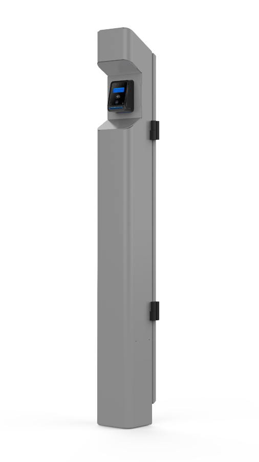
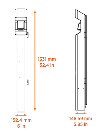
The pedestal is a vertical enclosure with a pre-installed credit card chip reader. The dimensions of the whole assembly are shown here.
-
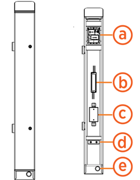
Payment terminal
-
DC power supply
-
Junction box
-
U-bolt and clamping bracket
-
Rear conduit entry
Pedestal Mounting Template
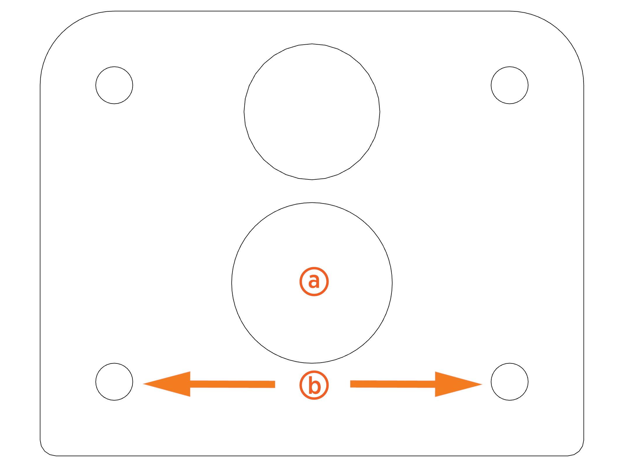
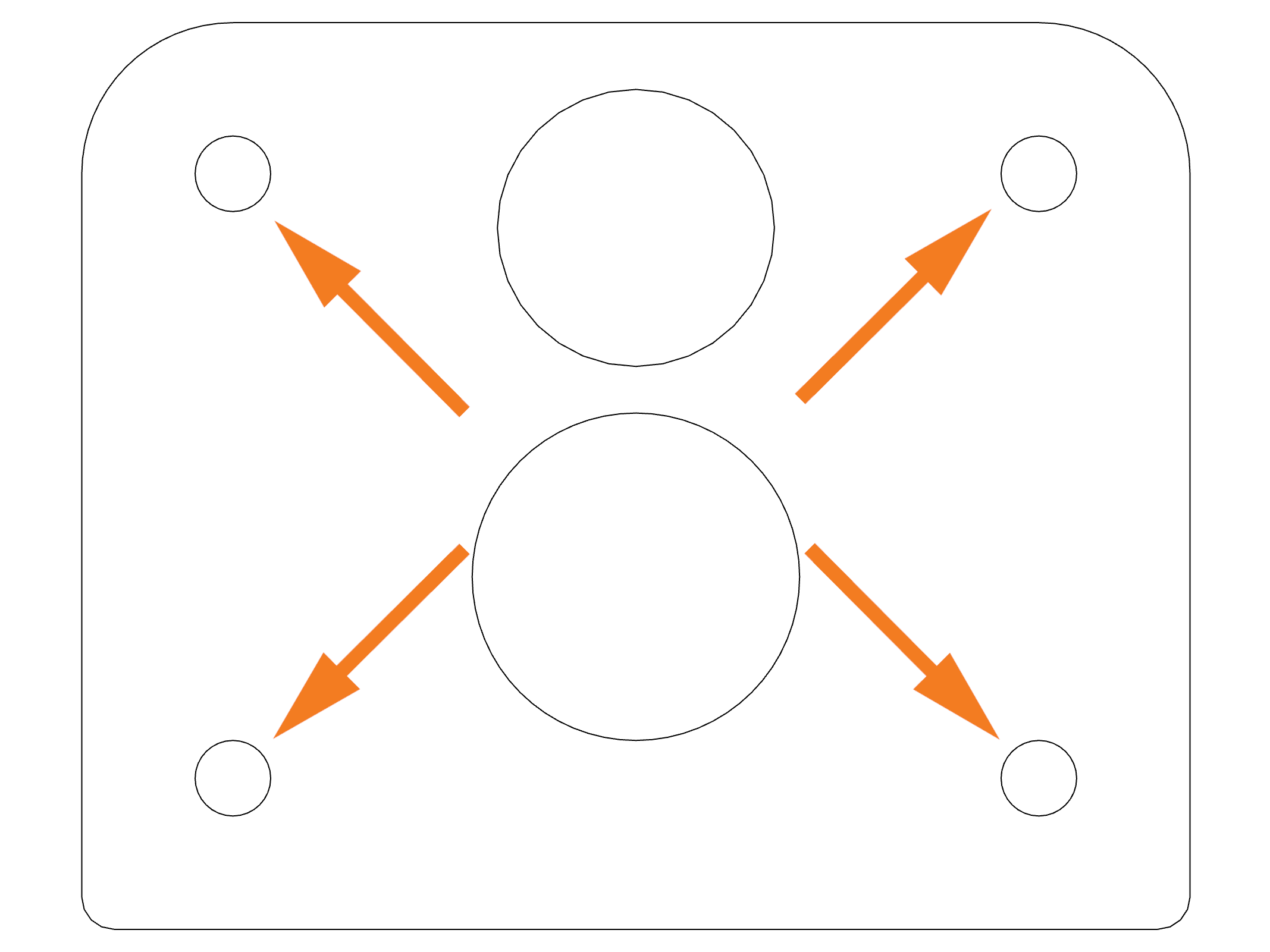
The pedestal is installed on either a concrete pad and secured with anchor bolts, or dirt and/or asphalt and secured with a mounting post and anchor bolts. The mounting template correctly aligns mounting hardware and conduit openings to ensure the pedestal can be easily installed and connected.
ChargePoint recommends concrete installation method when possible.
![]()
-
Bottom conduit entry: 34.93 mm (1.38 in)
-
Mounting post: 41.28 mm (1.63 in)
-
Anchor bolts: 9.53 mm (0.38 in)
After mounting hardware is installed in the correct configuration, the template is removed and later used as pedestal's base plate and fastened to the inside of the enclosure.
Details on how to prepare the concrete surface for anchoring and mounting are described later in this guide.
Electrical Requirements
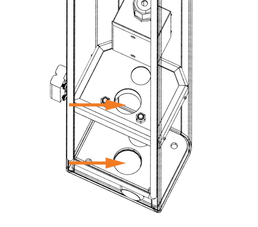
The pedestal installation requires service wiring to be installed and run through underground or surface conduit. Conduit can be run from either the bottom (a) or rear (b) of the enclosure. The conduit passes through an additional hole inside the enclosure (c) before it reaches the junction box.
![]()
![]()
-
Bottom conduit entry: 34.925 mm (1.375 in)
-
Rear conduit entry: 28.575 mm (1.125 in) - (3/4 in trade size)
CAUTION: An additional waterproof cable grommet is required for rear conduit pulls.
Conduit and wire size are determined based on the length of runs from the electrical panel to the pedestal location. Consult national and local codes or a project engineer to determine the grade, quality, and size of the conduit or cable.
All wiring and conduit is supplied by the contractor unless otherwise noted. Wire gauge is determined by the site's power requirements and conduit run length.
Electrical requirements are listed below:
-
Power requirements: 120 VAC. May be home run from the panel or derived from 480 VAC to 120 VAC step down transformer from the local disconnect switch.
-
Conduit requirements:
-
Conduit size: Up to 25.4 mm (1 in) outside diameter
-
Stub-up height: 419.1 mm (16.5 in)
Each payment terminal communicates with ChargePoint using a cellular network. No communication wiring is needed between the payment terminal and the charging station or building.
It is possible to daisy chain multiple pedestals if appropriate for the installation site.
The conduit should extend up to the bottom of the internal junction box.
Depth of conduit may vary by site as long as the stub-ups are vertical and placed correctly.
Additional Site Guidelines
-
The mounting surface must be completely dry during installation.
-
Consider how easily drivers can view and access the credit card chip reader pedestal when using the accompanying charging station.
-
Avoid placing pedestals in a location that obstructs access to the station's charging cables and main display.
-
Check local requirements for accessibility and pathway width, sometimes called "path of travel", to ensure pedestal placement does not restrict sidewalk use.
-
Ensure the pedestal installation complies with American Disability Act (ADA) requirements.
IMPORTANT: Always check local codes or consult an engineer to ensure the site is prepared in complicance with all applicable regulations. Local authorities might not allow a unit to operate if it is not installed to code.
Check the Pedestal Shipping Crate
Each pedestal ships in one crate. Crate specifications are listed below:
-
Maximum shipped dimensions: 1524 x 279.4 x 254 mm (60 x 11 x 10 in)
-
Maximum shipped weight: 9.98 kg (22 lb)
Before beginning work, confirm the crate contains all the following components:
-
ChargePoint Credit Card Chip Reader Pedestal
-
Rear panel door keys (x4)
-
ChargePoint Credit Card Chip Reader Pedestal Quick Guide
The pedestal enclosure should contain the following components:
-
Pedestal mounting template
-
U-Bolt
Required Tools and Materials
Ensure that the following tools and materials are onsite, depending on the installation method:
Dirt and asphalt:
-
1 in trade size rigid conduit
Conduit length should run from 12 to 16 in above and below ground.
-
3/8-16 in anchor bolt (x2)
-
3/8 in washer (x2)
-
3/8 in lock washer (x2)
-
3/8 in nut (x2)
Concrete:
-
3/8-16 in anchor bolt (x4)
-
3/8 in washer (x4)
-
3/8 in lock washer (x4)
-
3/8 in nut (x4)
-
Epoxy adhesive for concrete
-
Brush or compressed air
Use anchor bolts such as the Simpson Strong-Tie (Part Number STB2-37300-18-8SS) or similar.
In addition, the installer needs the following tools and materials for all installations:
-
Wire splice connectors (x2)
-
14 mm (9/16 in) torque wrench capable of 20 Nm (15 ft-lbs)
-
Hammer drill and drill bits
-
Flathead screwdriver
-
Standard electrical equipment such as wire cutter, wire stripper, and cable ties
-
Lockout/tag out equipment
-
Cut-resistant gloves
-
Safety glasses
-
Head-mounted flashlight
-
Isopropyl alcohol wipes
-
Lint-free cloth
Prepare for Installation
This section describes how to prepare the installation site so that the pedestal is correctly mounted on an existing concrete surface. To prepare for installation, complete the following steps:
DANGER: RISK OF SHOCK. Follow standard practice and local code to de-energize the applicable circuit and lock out/tag out the disconnect before proceeding. Use a multimeter to test that power is off. FAILURE TO FOLLOW THESE INSTRUCTIONS CAN RESULT IN SERIOUS INJURY OR LOSS OF LIFE.
-
Remove the pedestal and packaging material from the shipping crate.
-
Using one of the keys attached to the pedestal, unlock and open the rear panel door. Save the keys to provide to the station manager once installation is finished.
-
Remove the rear panel door from the pedestal by sliding the panel up and out of its hinges.
-
Remove the mounting template from the enclosure. The template is secured to the bottom of the pedestal with a zip tie.
-
Place the mounting template at the planned pedestal installation area. If using the bottom conduit opening, place the conduit through the conduit hole on the template.
Dirt and asphalt:
-
Using the mounting template as a guide, mark the hole locations on the ground:
-
Mounting post
-
Anchor bolts (x2)
-
Drill mounting post hole: 304.8 mm (12 in) diameter, 508 to 609.6 mm (20 to 24 in) deep.
-
Drill two anchor bolt holes following manufacturer's instructions.
-
Insert the mounting post into its hole location and pour concrete.
-
Remove the template to use in a later step.
When installed correctly, the anchor bolts should be located within the rear corners of the enclosure.
Concrete:
-
Using the mounting template as a guide, mark the four anchor bolt holes on the concrete.
-
Drill four anchor bolt holes following manufacturer's instructions.
-
Remove the dust from the holes using a brush and compressed air or a vacuum.
-
Fill the holes with epoxy to below grade. Be mindful of the cure time to make sure you can insert and position the bolts before the epoxy sets up.
-
Insert the bolts into the holes. Ensure the bolts protrude approximately 25.4 mm (1 in) from the top of the concrete.
-
Rotate the bolts to ensure the epoxy penetrates the anchor bolt threads. Take care to avoid getting epoxy into the above-grade threads.
-
Place the template over the bolts to ensure they remain in the correct position as the epoxy or concrete cures.
-
Remove the template to use in a later step.
-
Allow the epoxy to cure completely before continuing installation.
Mount and Secure the Pedestal
To mount and secure the pedestal, complete the following steps:
Dirt and asphalt:
-
Lift the pedestal and move it to the mounting location.
-
Loosen, but do not remove, the two nuts securing the U-Bolt to the clamping bracket and middle plate. This allows the mounting post to pass through the pedestal enclosure.
-
Place the mounting template at the bottom of the enclosure. The template holes should align with the holes in the pedestal.
-
Align the ground post, anchor bolts, and bottom conduit (if applicable) with the matching holes at the bottom of the pedestal enclosure.
-
Carefully lower the pedestal to the ground so that all components pass through their matching holes. Verify that the center ground post passes through the holes on the pedestal floor, mounting template, U-Bolt, and middle plate.
-
Use a torque wrench to fasten each threaded rod with a 3/8 in washer, lock washer, and nut.
-
Tighten the two nuts on the U-Bolt so that the pedestal is tightly secured in between the U-Bolt and the clamping bracket.
Concrete:
-
Lift the pedestal and move it to the mounting location.
-
Align the anchor bolts and bottom conduit (if applicable) with the matching holes at the bottom of the pedestal enclosure.
-
Carefully lower the pedestal to the ground so that the anchor bolts and conduit pass through their matching holes.
-
Place the mounting template at the bottom of the enclosure.
-
Fasten each anchor bolt with a 3/8 in washer, lock washer, and nut. Torque to 20 Nm (15 ft-lbs).
Connect the AC Wiring
To connect AC wiring, complete the following steps:
-
Follow standard practice and local code to de-energize the applicable circuit and lock out/tag out the disconnect before proceeding. Use a multimeter to test that power is off.
-
If using the rear conduit opening:
-
Remove the cap from the conduit opening by pushing outward from the inside of the enclosure.
-
Using waterproof connecter seals, connect the conduit to the enclosure per applicable code.
-
Route the conduit through the grommet and the conduit hole at the front end of the middle plate.
-
If not already done, pull service wiring through the conduit.
-
Strip the wires to the length appropriate for the connector used.
-
Use a flathead screwdriver to open the junction box.
-
Loosen the bottom cable gland and run service wiring through.
-
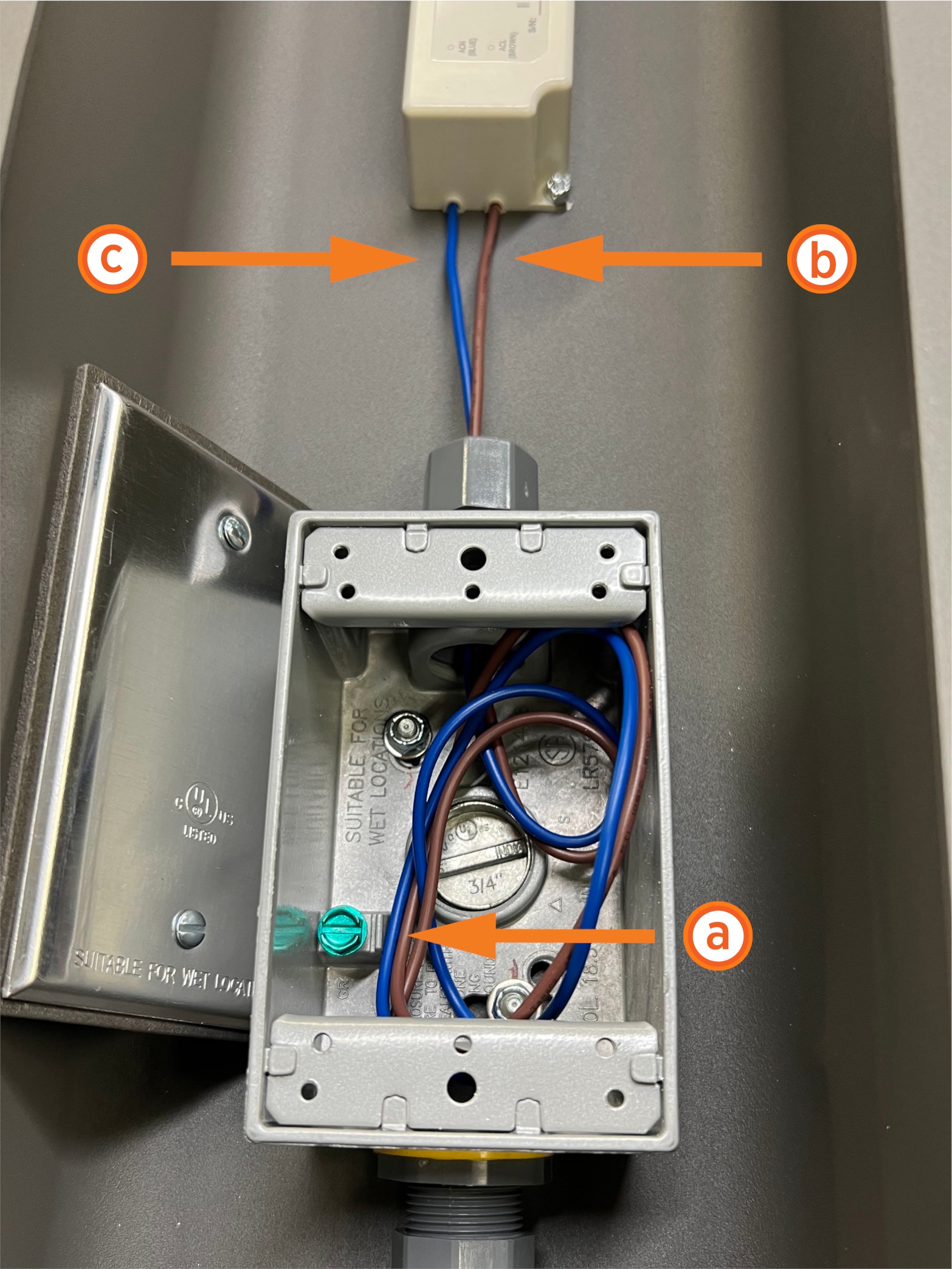
Using a flathead screwdriver, make the AC ground connection inside the junction box, landing the ground on the green screw (a).
-
Secure the remaining service wiring to the DC power supply wiring:
-
Power wiring (b)
-
Data wiring (c)
-
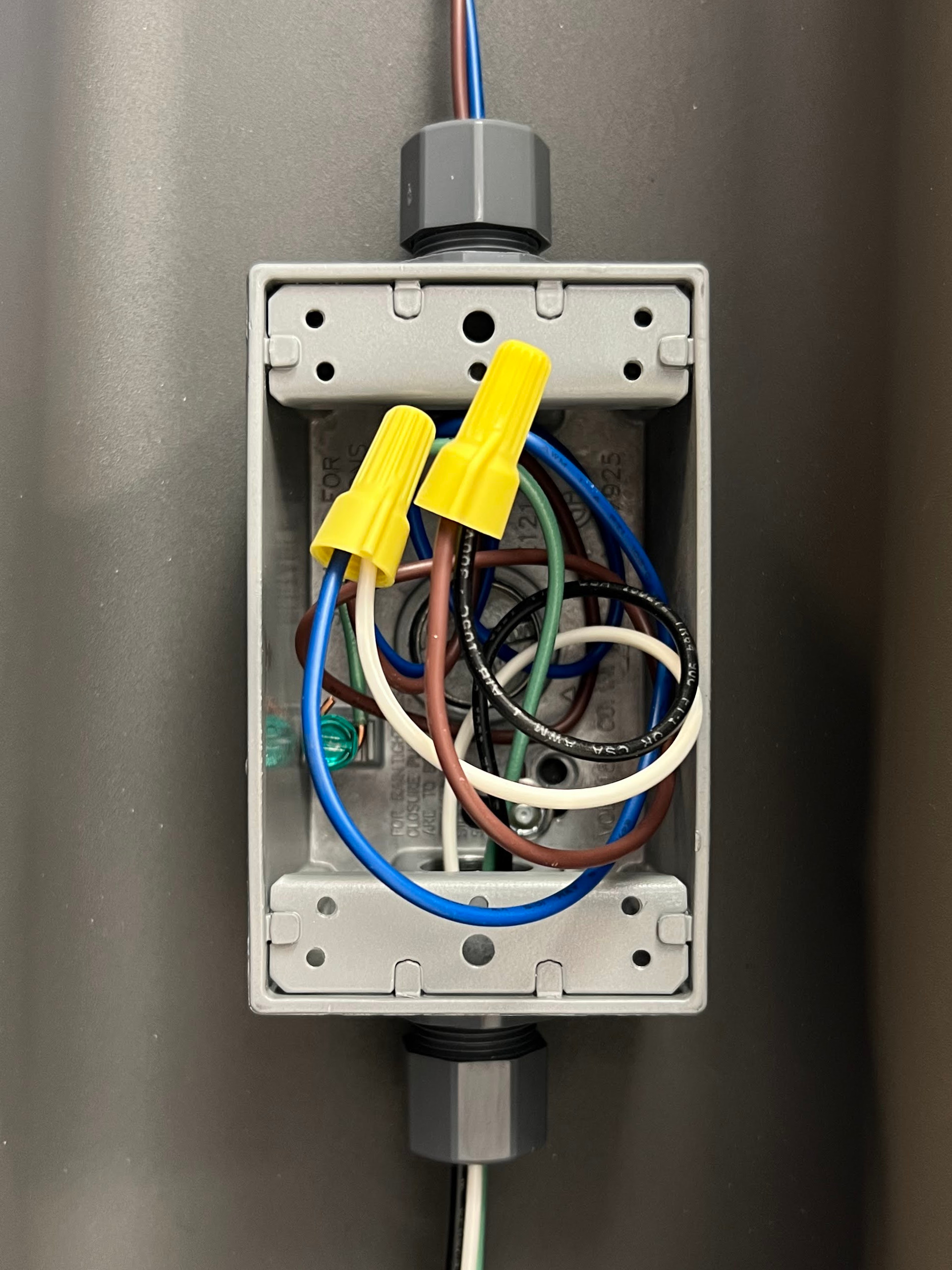
Ensure the connections are secure and protected from moisture.
DANGER: Ensure the exposed wires are tightly bundled with no loose strands. Loose or missing strands can cause arcing or a similar electrical hazard that could result in property damage, injury, or death.
-
After confirming the wiring is properly connected, tighten the cable gland and close the junction box.
-
Close and lock the rear panel door to complete installation.
Pair the Payment Terminal
The station must be paired to the payment terminal before installation is complete. This requires the installer to have both the station and payment terminal serial number. To pair the payment terminal, complete the following steps:
-
Locate the serial numbers:
-
Charging station: Next to the ratings label, either above the top rear panel (Express 250 or Express 280) or on the back right edge of the heat sink (Power Link 1000)
-
Payment terminal: On the side of the pedestal (next to the QR
 Quick Response code) or the back side of the terminal

-
Use a smart phone to scan the QR
Quick Response code. This takes you to a web form.
-
Input the serial numbers of the station and payment terminal, as well as all other required fields.
-
Submit the form once all fields are completed.
Complete the Installation
Once installation is complete and power is turned on, the payment terminal automatically begins its boot-up process. When the message “Powered by PTOS” is displayed on the idle screen, the terminal is ready for activation.
If the terminal does not display the “Powered by PTOS” message after waiting for start up, or if an error code pops up on screen, contact ChargePoint support.
IMPORTANT: If the terminal does not power on, open the pedestal unit and check if the cables are properly connected to the terminal.
