Install Doors
(Standard Pedestal)
Power On 48 V
-
Locate the 48 V DC breaker.

-
Flip up the switch to ON. The indicator light should turn red.

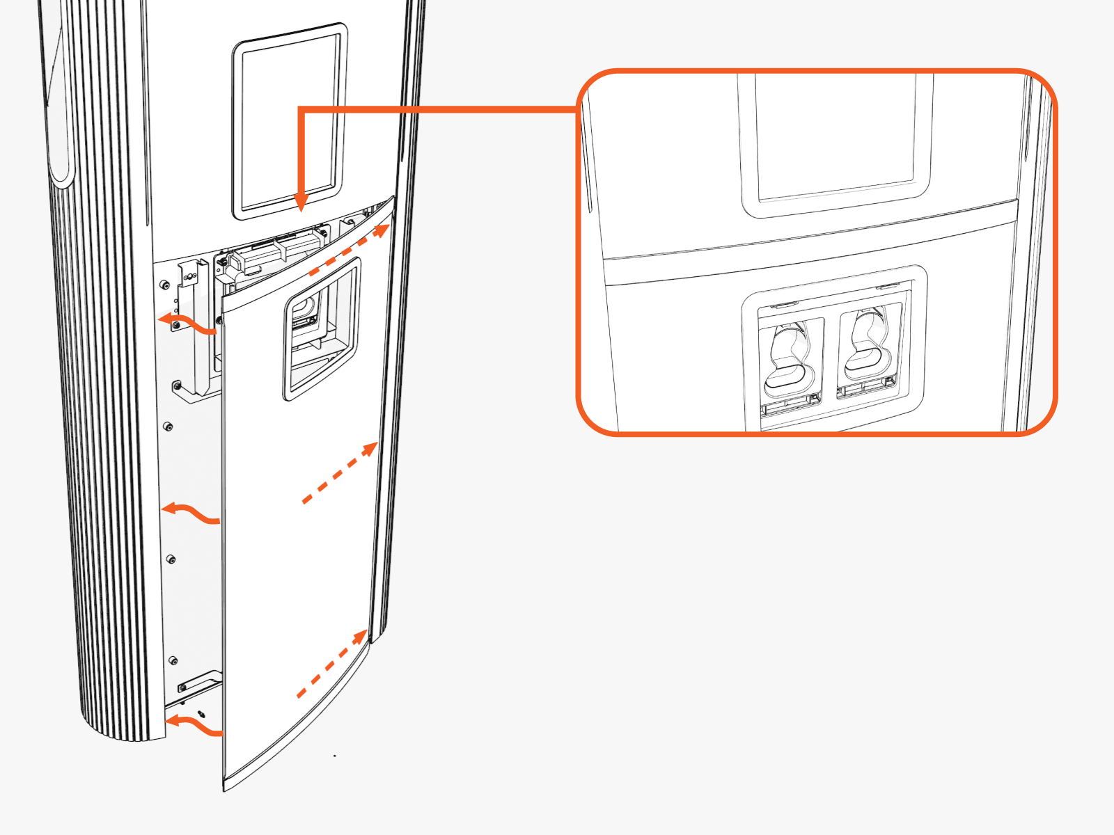
Install Upper Door
If your unit has a lower safety panel that you did not yet reinstall, do so now.
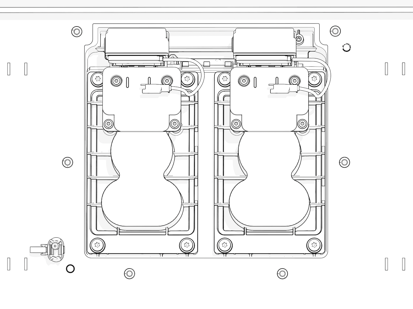
Install and Connect Holsters
-
Match each holster to the connector type for each charging cable on each side.
-
Fit the correct holster into the opening at the center. Install screws into each holster.
-
Optional lock feature:
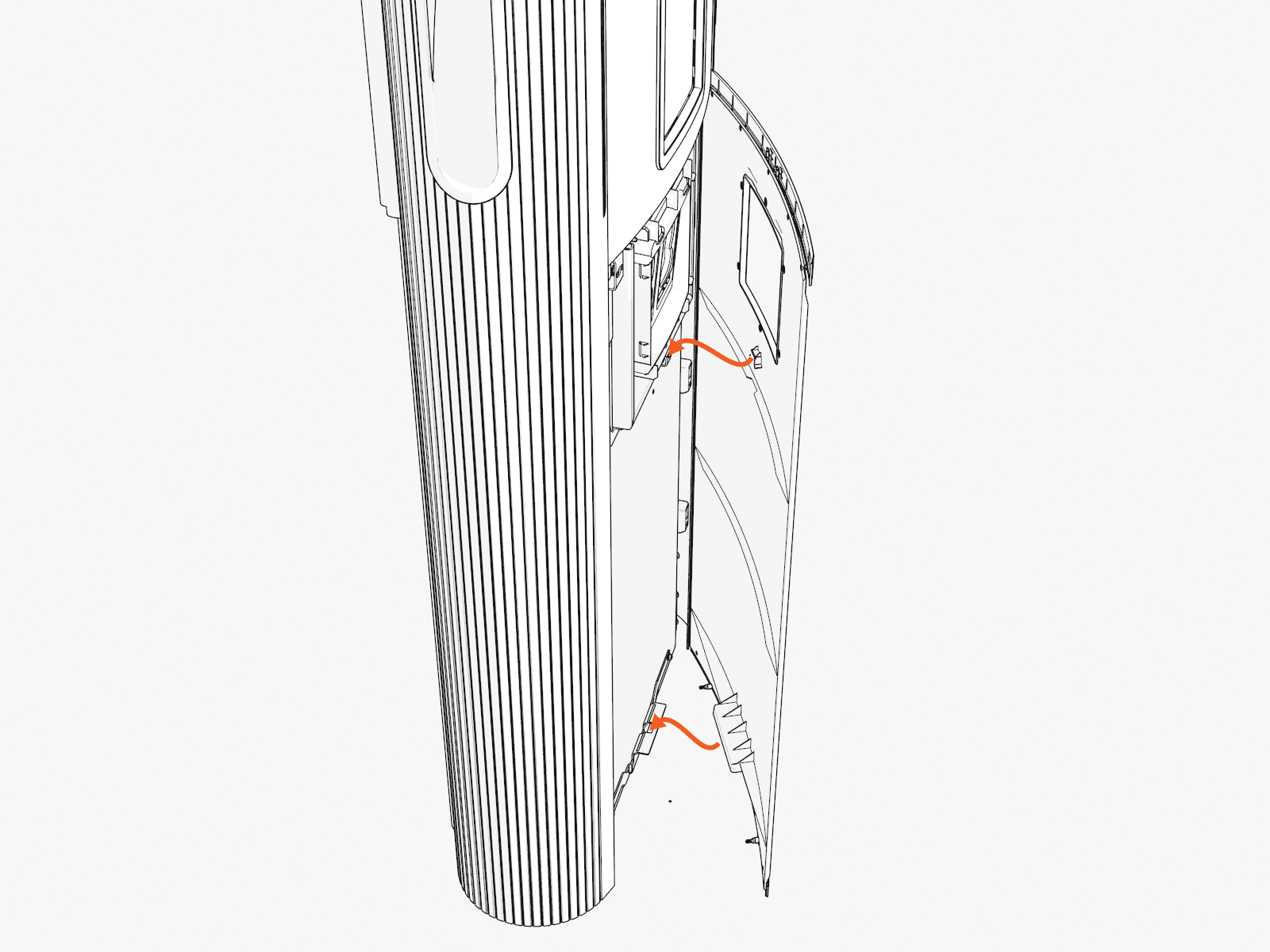
Route and connect the wiring to each holster.
-
Route the wiring harness through the notch (at right) in the lower safety panel.
-
Locate the markings "1" and "2" on the housing at the base of the wires.
-
Connect the holster near the door hinge to wire "2".
-
Connect the holster near the door opening to wire "1".
-
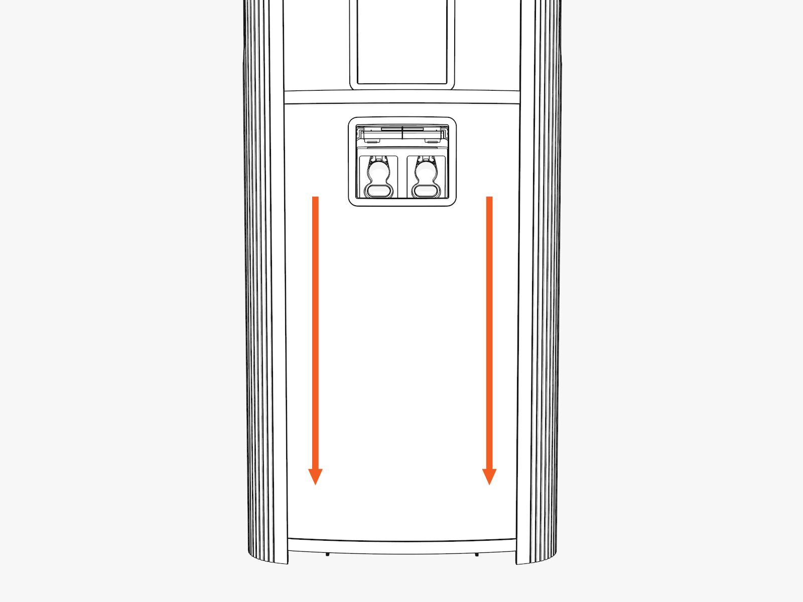
Install Lower Door
-
Disengage wind stops and close the door.
-
Torque screws on the door to 4.5 Nm (40 in-lb).
-
On the right side of the door, insert the bottom of the door bracket. Tilt in the top of the door bracket. Push down into position.
-
Torque screws on the door bracket to 1 Nm (10 in-lb).
Install Covers
(Standard Pedestal)
Identify if you have preassembled covers or unassembled components (vinyl signs, trims, and top cap).
To request a change, contact ChargePoint Support (chargepoint.com/support).
Continue to the applicable instructions.
A. Install Preassembled Covers
-
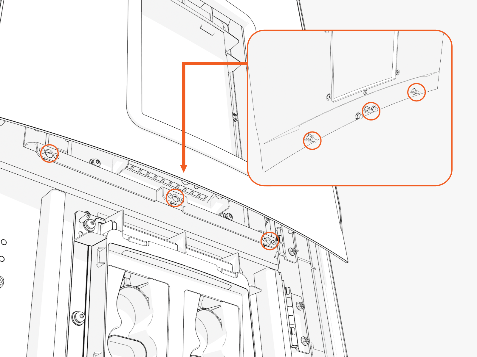
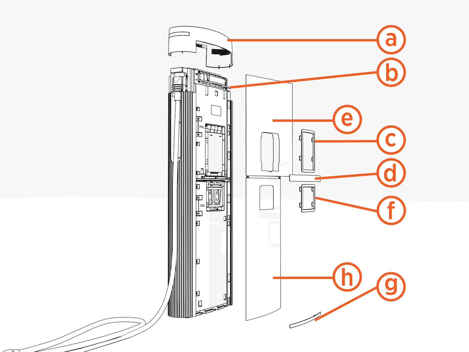
Notice the three brackets on the doors. Pins and hooks on the covers fit into these.
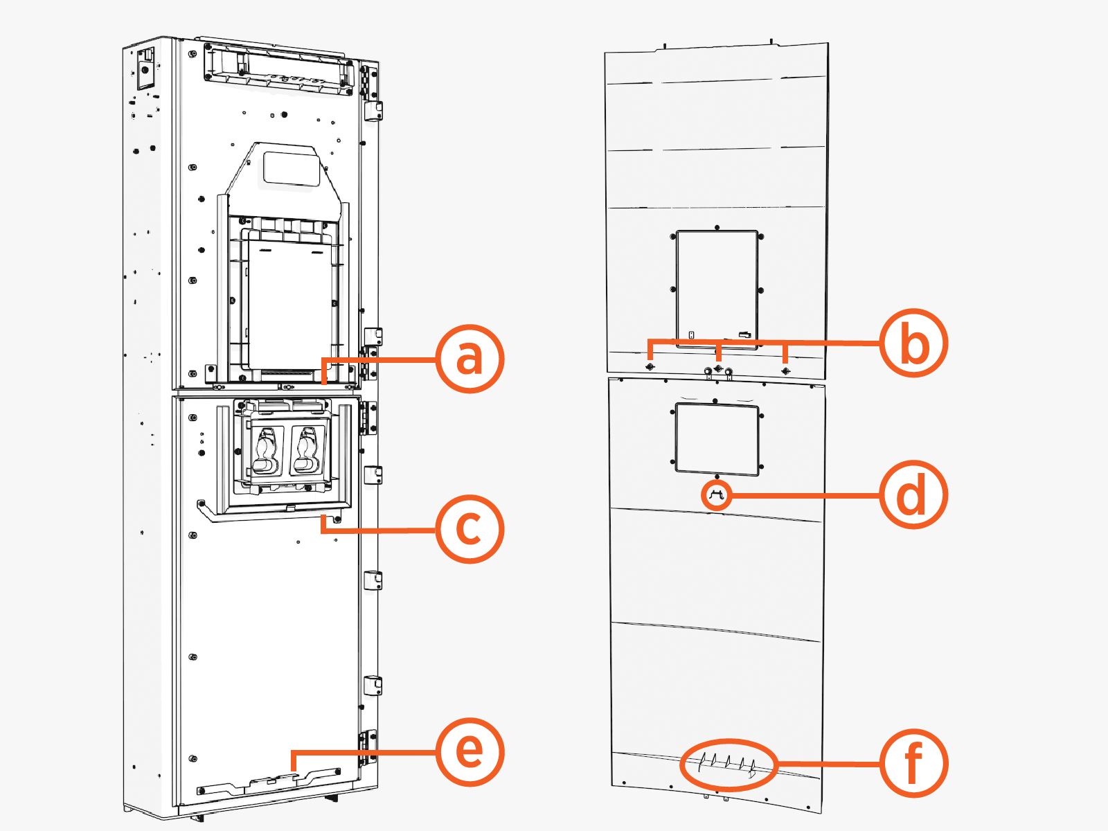
Upper door and cover:
(a) Upper bracket with three clips
(b) Three pins
Lower door and cover:
(c) Middle bracket
(d) Middle hook
(e) Lower bracket
(f) Lower hook
Front Covers
| Left Groove |
Right Groove |
|
|
|
Upper Cover
-
Slide the left or right edge of the cover into the left or right groove.
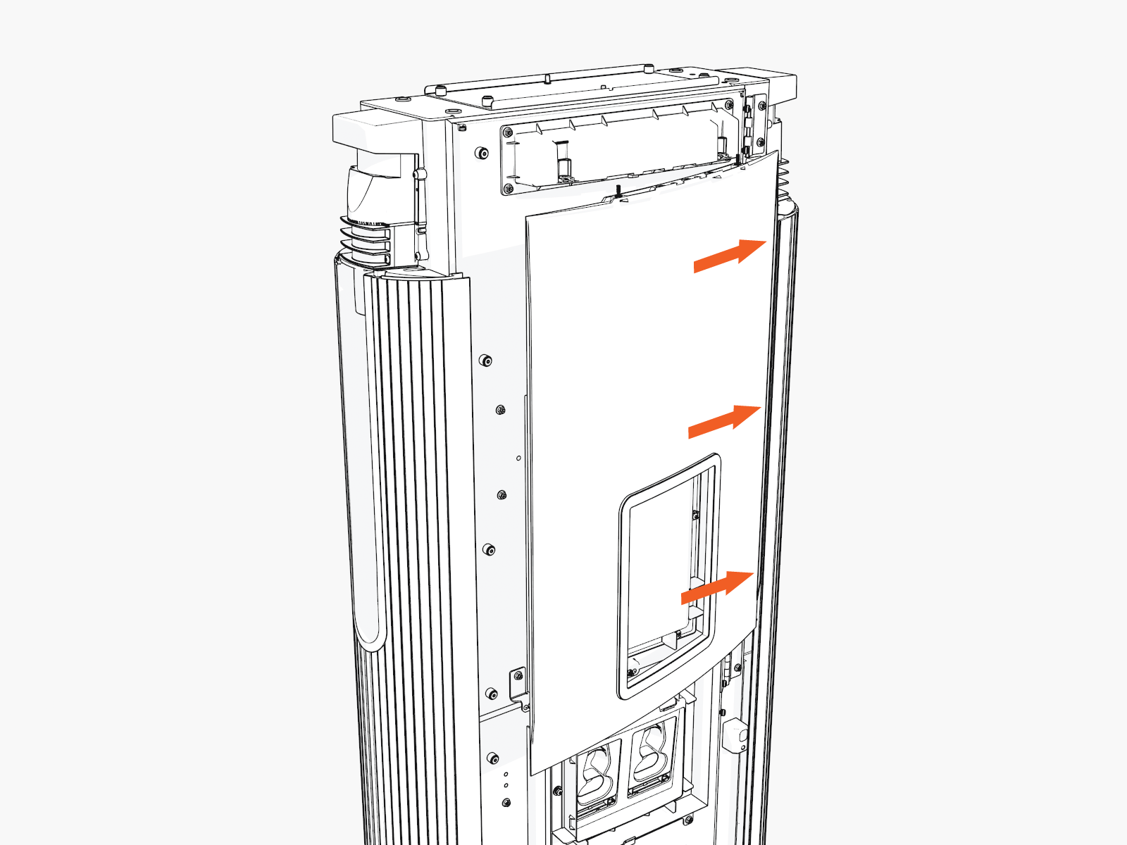
-
Rotate and bend in to slide the other edge into the other vertical groove.
While rotating in, ensure the captive screws at the top edge of the cover do not come in contact with the downlight housing.
-
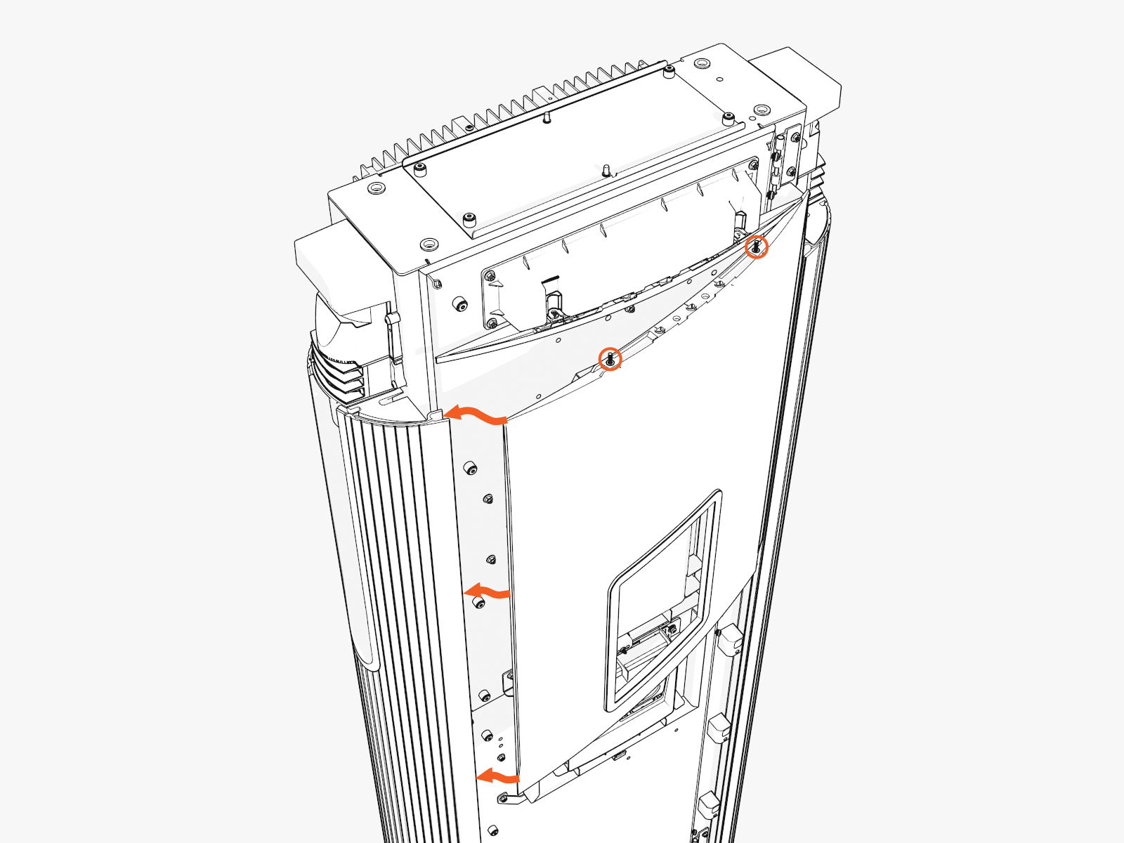
Hold and flex the bottom center of the cover slightly outward and slide it up to mate with the downlight housing. Align and seat the captive screws with the openings in the downlight housing (screws will be tightened later when the top cap is installed).
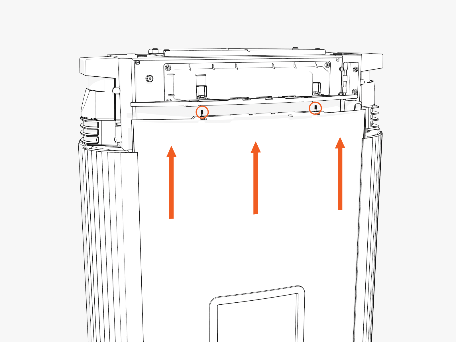
While flexed, align the three ball studs on the cover with holes into the bracket on the door, and press the cover in to clip in the ball studs.
Lower Cover
-
Slide the left or right edge of the cover into the left or right groove and then rotate and bend in to slide the other edge into the other vertical groove.
While sliding in the edges, hold the top edge of the lower cover just below the lower edge of the CCOM
 Control and Communications Module trim, or overlap the top portion of the lower cover about 30-35 mm (1.25-1.5 in) over the bottom portion of the upper cover.
-
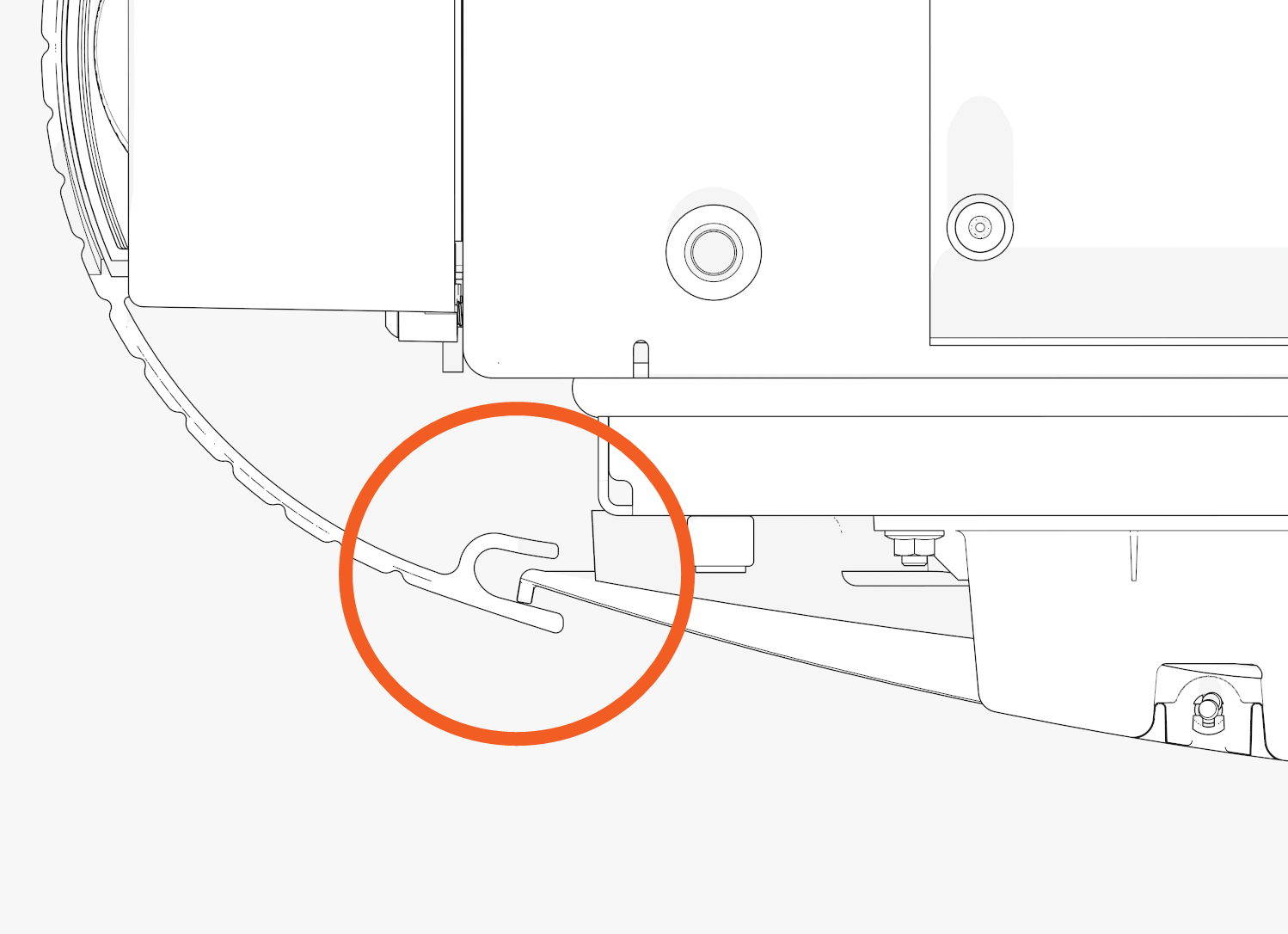
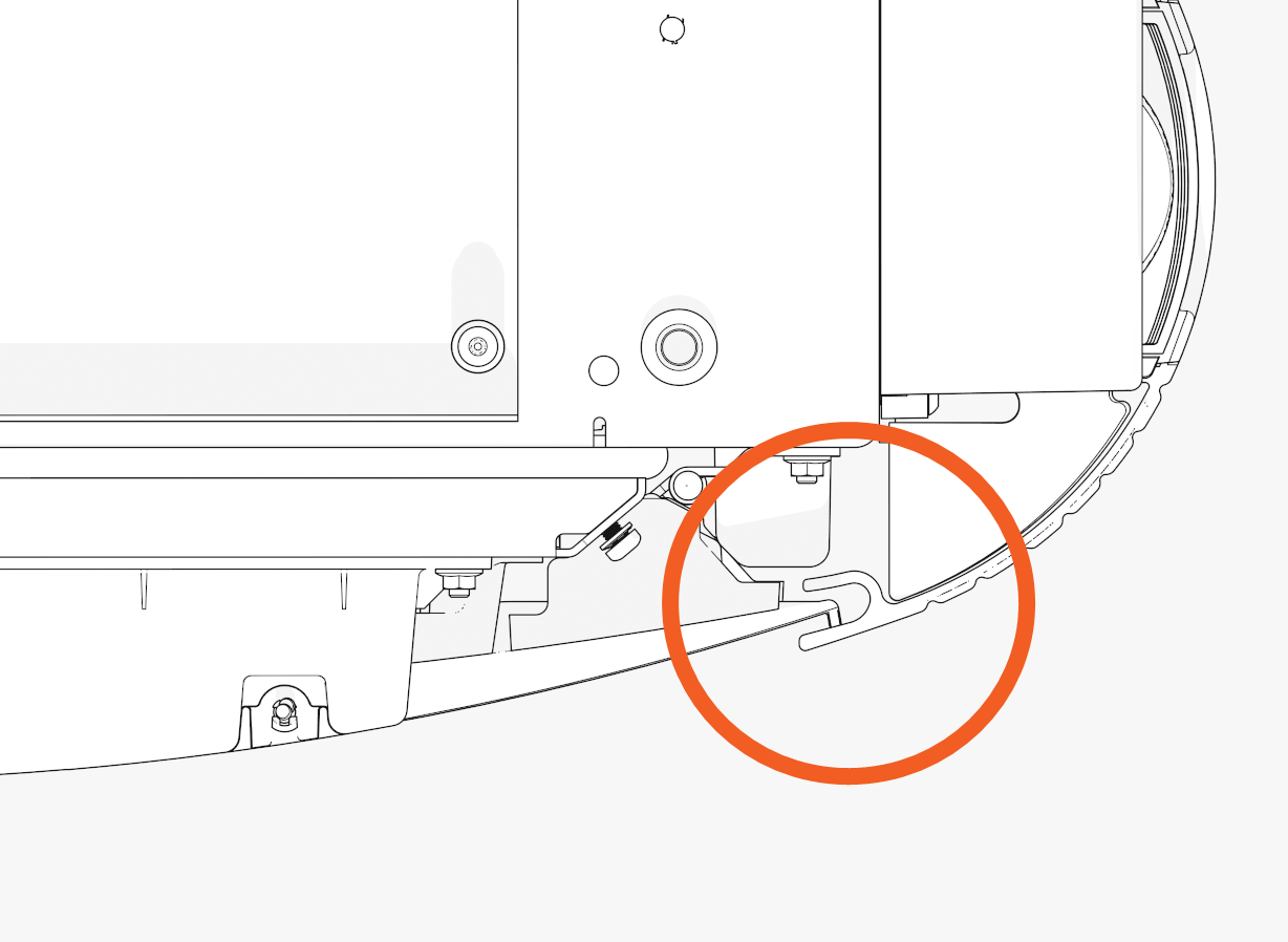
Check the top and bottom corners to make sure the edges are seated in the groove, and then slide the cover down. While sliding down, press in on the lower edge of the holster trim and lower edge of the cover to engage the hooks behind the cover.
Top Cap
-
Align the screws (x4) (two at front and two at rear) and install the top cap.
Front

Rear

-
Torque the M5 screws (x2) at rear side to 2.8 Nm (25 in-lb) and M4 screws (x2) at front side to 1.7 Nm (15 in-lb) (use T25 security screwdriver).
B. Install Vinyl Signs, Trims, and Top Cover
-
Top cover (helmet)
-
Upper trim
-
Interactive display trim (optional)
-
Middle trim
-
Upper vinyl sign
-
Holster trim
-
Lower trim
-
Lower vinyl sign
-
Identify the lower trim piece and study the orientation mark..
Notice the imprint on the trim shows which edge goes "UP."
-
Push in the lower trim until it engages with the center and side clips.

-
Insert the lower cover behind the lower trim. Simultaneously insert both sides of the lower cover.

-
Hook the upper side of the holster trim onto two hooks and rotate in. Then, press the lower side of the trim into place.

-
Insert the upper cover into each side.
Logo is on upper left.
-
Align the upper cover and the ends of the middle trim. Hold the cover in position so that it does not block the trim clips.

-
Push in the middle trim until it engages with the center and side clips.

-
Align the upper trim with the magnetic side up. Insert the upper trim until it snaps into position.

-
Hook the upper side of the CCOM
Control and Communications Module trim onto two hooks and rotate in. Then press the lower side of the trim into place.
-
Align the screws (x4) (two at front and two at rear) and install the top cap.
Front
Rear
-
Torque the M5 screws (x2) at rear side to 2.8 Nm (25 in-lb) and M4 screws (x2) at front side to 1.7 Nm (15 in-lb) (use T25 security screwdriver).
Continue to Charging Cable Instructions
Check your site plans to identify your hanging mechanism. Follow the applicable instructions below:
-
Standard cable management kit (CMK) with swingarms (onto Power Link 1000)
-
Tool balancer (onto another surface)
Before installing the tool balancer, you must first mount and install the Power Link 1000 to an approved surface (wall, post, gantry, or similar structure).
A CMK![]() Cable Management Kit includes swingarms that attach directly to the Power Link 1000 station to manage standard-length (i.e., 4.6 m or 15 ft) charging cables. A tool balancer is attached to a separate structure to manage medium-length (i.e., 7.6 m or 25 ft) charging cables but uses the same ball clamp.
Cable Management Kit includes swingarms that attach directly to the Power Link 1000 station to manage standard-length (i.e., 4.6 m or 15 ft) charging cables. A tool balancer is attached to a separate structure to manage medium-length (i.e., 7.6 m or 25 ft) charging cables but uses the same ball clamp.
