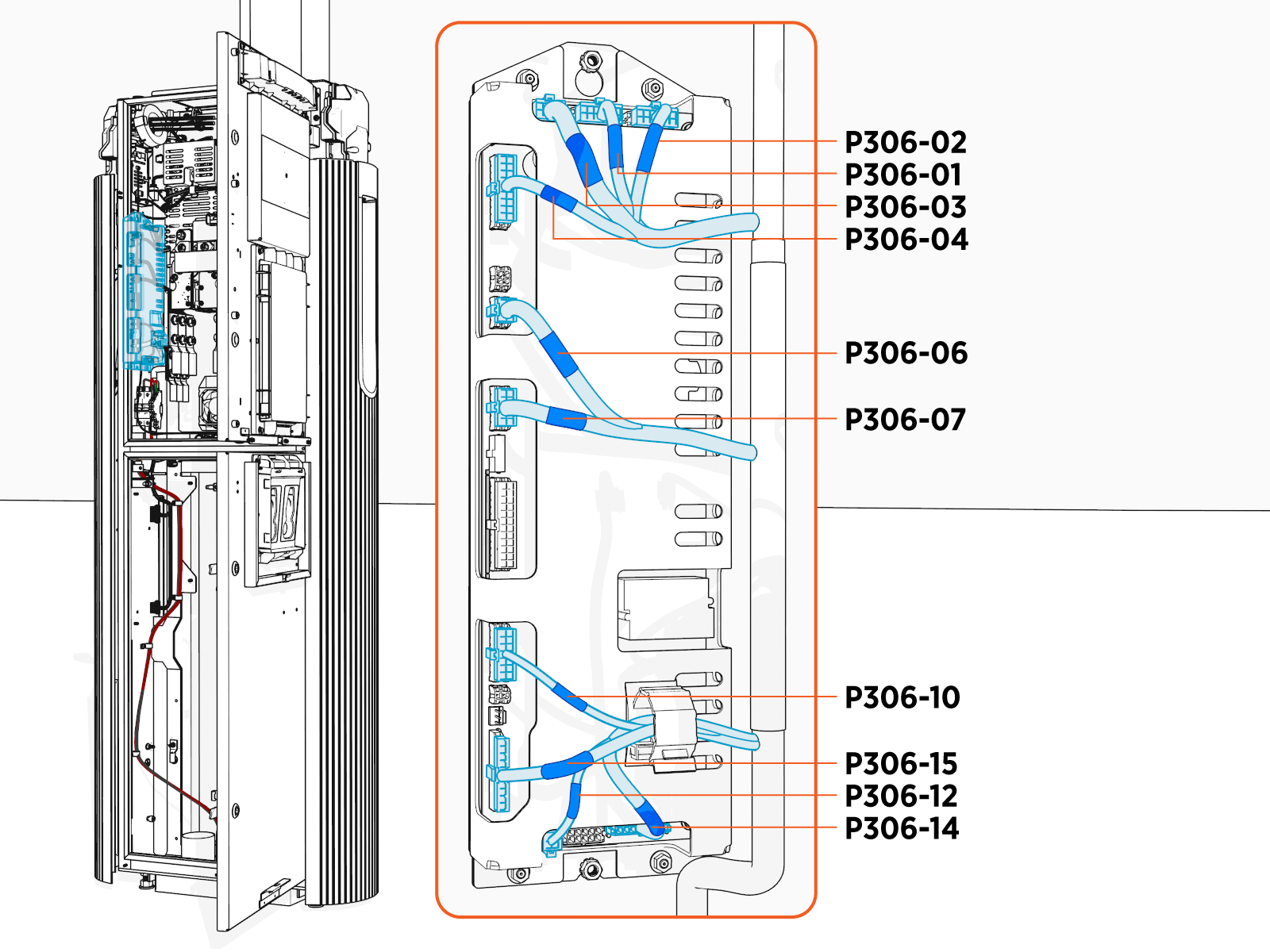
FDC Location
The illustration below shows the Power Link 2000 FDC (Power Link Controller) location.
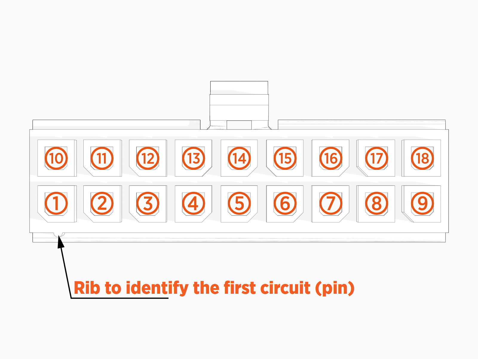
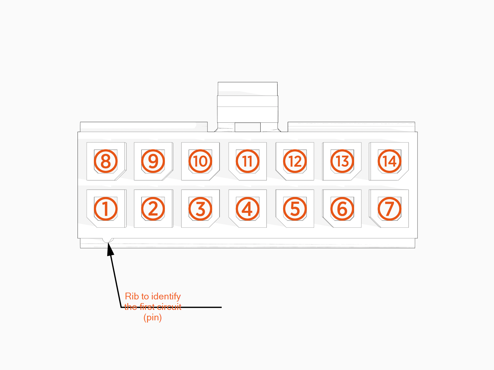
FDC Connectors' Pin Configuration
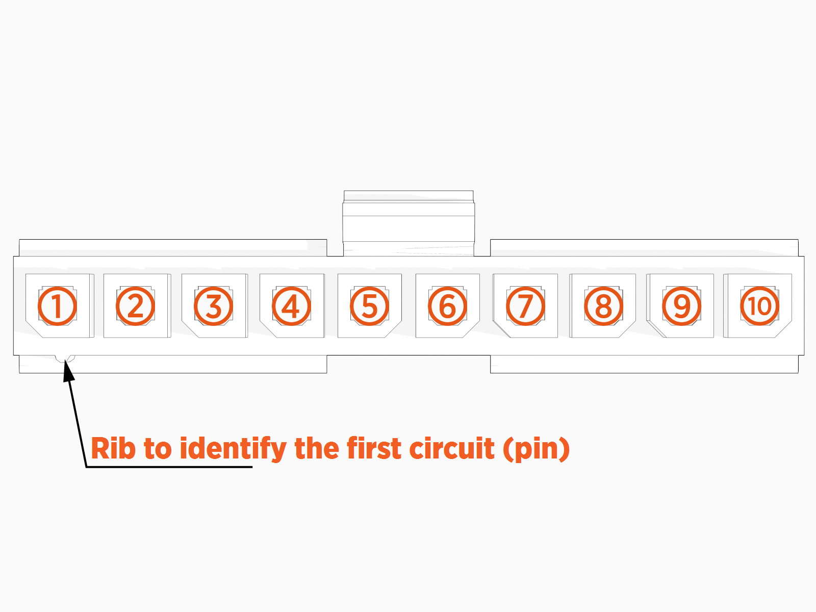
The illustrations below show the pin maps for the FDC cable connectors.
P306-04
P306-07
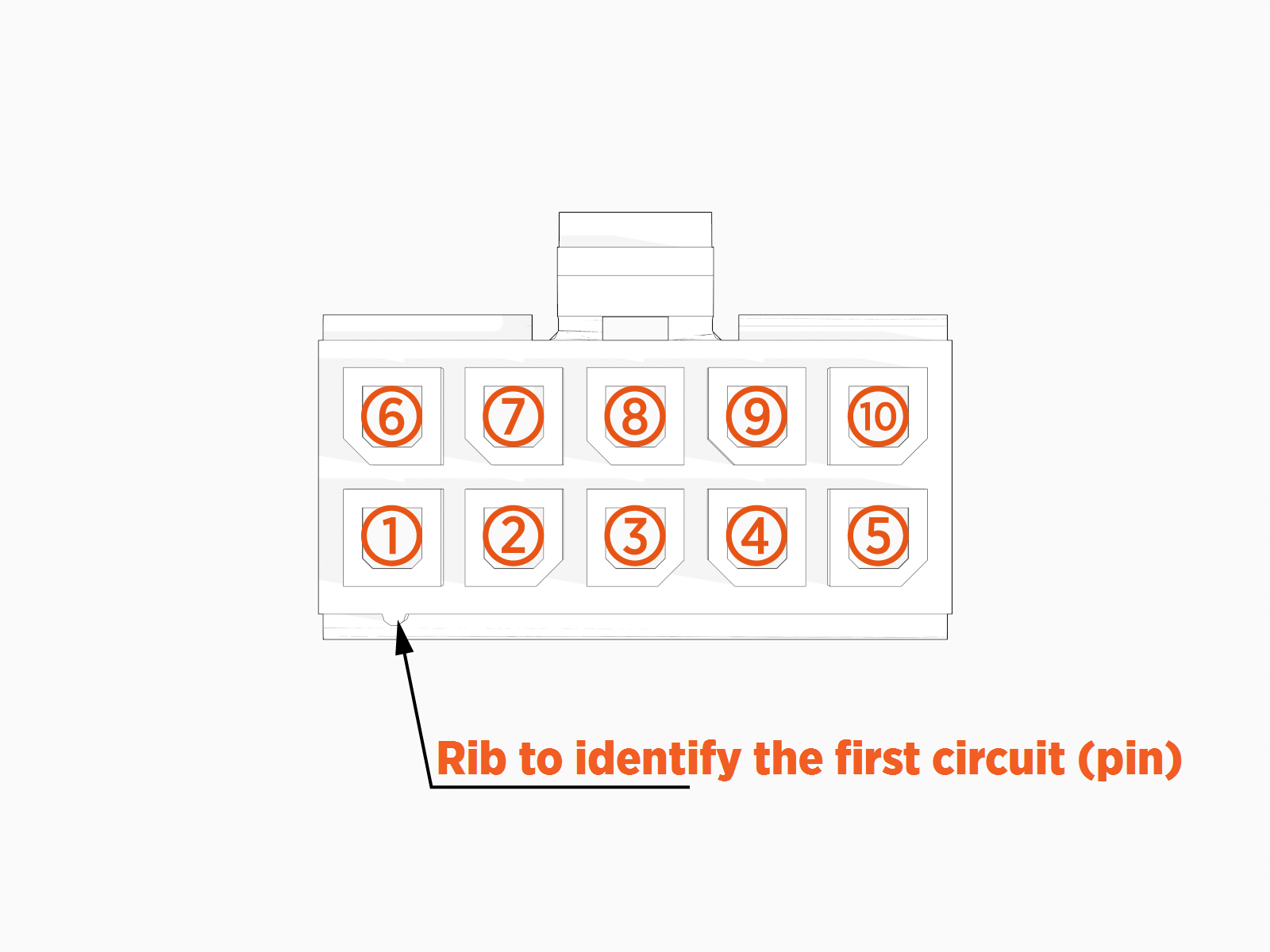
P306-10
P306-14
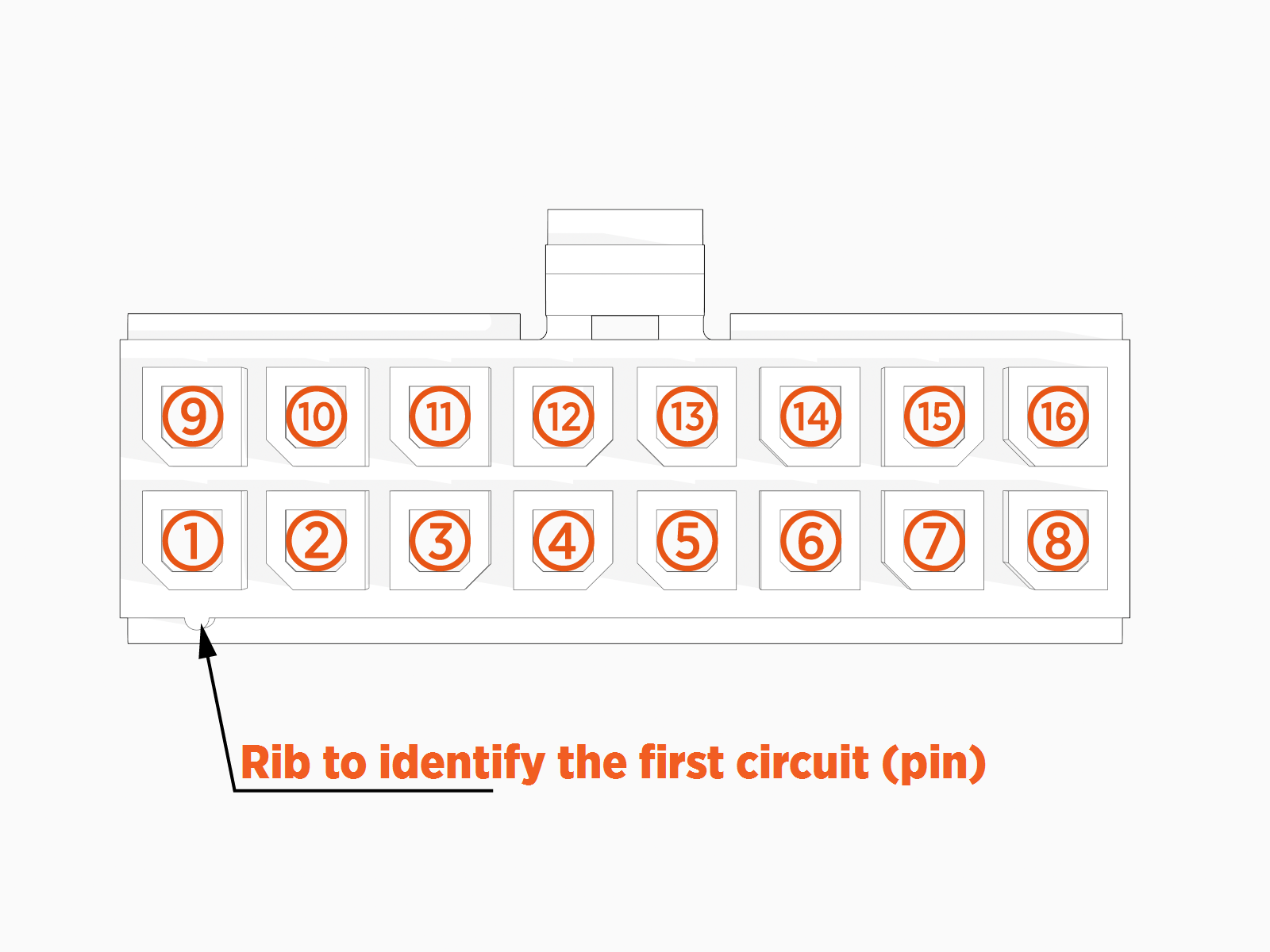
P306-15
FDC Faults
This section provides information on FDC faults, including fault characteristics, possible causes, and recommended troubleshooting steps.
urn:fault:fdc:Loss-Comms-with-UCB
|
Category |
Fault Source |
Fault Type |
Criticality |
|
FDC communication |
FDC |
Hardware/Software |
Emergency |
Fault Description
UCB![]() Universal Controller Board monitors the loss of CAN communications with FDC, monitors the heartbeat signal, and triggers a fault when there is no heartbeat for 5 seconds.
Universal Controller Board monitors the loss of CAN communications with FDC, monitors the heartbeat signal, and triggers a fault when there is no heartbeat for 5 seconds.
Possible Causes
-
Issue with CAN harness (connector, CAN termination, etc.).
-
FDC board failure.
Troubleshooting
-
Check if the P306-15 connector that carries CAN signals is seated correctly and locked in. If not, reseat it and confirm if the issue clears.
-
If no connector seating issue is found, then measure continuity between CAN_H (pin 7) and CAN_L (pin 8). Check if there is a short between the CAN H and CAN L lines; if yes, then replace the harness.
-
Confirm if the CAN termination is good; measure resistance across CAN_TERM (pin 4) and CAN_TERM (pin 5).
-
If no issues are found with the connector and harness, then replace the FDC board due to possible board issues.
-
Contact engineering for further debugging steps.
urn:fault:fdc:Checksum-Failure
|
Category |
Fault Source |
Fault Type |
Criticality |
|
FDC Firmware |
FDC |
Firmware |
Critical |
Fault Description
This fault triggers when the FDC firmware version and checksum don’t match the expected version after two attempts to reflash. Ideally seen during a new install or when software is updated on the system. However, if this is seen during an ongoing session, then the session is immediately terminated and Power Link 2000 is locked out of service.
Possible Causes
-
Bad FDC firmware flash at factory.
-
Interruption during software update.
-
Board firmware getting corrupted.
Troubleshooting
-
If the UCB
 Universal Controller Board board had an issue during the finalizer step, then it is possible it is pushing a bad FDC firmware, so login to chassis-shell and confirm if FDC is reading the correct firmware version.
 -
If the above is true, then try to flash the UCB
Universal Controller Board again to see if it pushes FDC to recover. -
If this happened during the software update in the field, try to power cycle it and see if it recovers.
-
If the power cycle does not help, then replace the FDC board.
urn:fault:fdc:Vicor-Overtemp-Shutdown
|
Category |
Fault Source |
Fault Type |
Criticality |
|
FDC Board |
FDC |
Hardware/Software |
Critical |
Fault Description
This warning triggers when one of the modules on the FDC board reports 90 °C for 10s.
The fault occurs when the temperature drops below 100 °C for more than 60s.
Possible Causes
-
FDC board failure.
Troubleshooting
No action is required as the system is allowed to operate normally with this warning.
urn:fault:fdc:Board-Overtemp-Shutdown
| Category | Fault Source | Fault Type | Criticality |
| FDC Board | FDC | Hardware | Critical |
Fault Description
The fault triggers when one of the modules on the FDC board reports 100 °C for 10s. A 30 minute cooldown period is added after the fault. The fault clears when the temperature drops below 100 °C for more than 60s. Power Link 2000 is locked out if this fault is seen three times within 24 hours. UCB![]() Universal Controller Board will record critical parameters as part of the snapshot feature.
Universal Controller Board will record critical parameters as part of the snapshot feature.
Possible Causes
-
FDC board failure.
Troubleshooting
-
Replace the FDC board if Power Link 2000 is locked out.
-
Contact engineering if replacing the FDC does not resolve the issue.
urn:fault:fdc:Top-RTD-Overtemp-Shutdown
|
Category |
Fault Source |
Fault Type |
Criticality |
|
PL RTD |
FDC |
Hardware |
Critical |
Fault Description
This overtemperature shutdown triggers when the top RTD exceeds 95 °C (<125 °C) for 10s. If the session continues, then it is an emergency. The fault clears when the temperature drops below 95 °C for 60s. Power Link 2000 locks out if the fault appears three times within 24 hours. UCB![]() Universal Controller Board will record critical parameters as part of the snapshot feature.
Universal Controller Board will record critical parameters as part of the snapshot feature.
Possible Causes
-
Issue with the harness.
-
Failure of Top RTD (located above MDS - back plane).
-
FDC board.
Troubleshooting
-
Check if the wires 1 and 2 on P306-10 are pulled out of the connector with a basic pull test.
-
Measure the resistance across Pins 1 and 2 on connector P306-10 to check if the harness between RTD and FDC is not broken. You will measure 100 Ω if the switch is good. If the switch reads bad, then replace the RTD to resolve the issue.
-
If the issue persists after replacing the switch, confirm that the feedback wire is not broken. Measure continuity across pin 1 (on P306-10), pin 2 (feedback wire on RTD), and continuity across pin 2 (on P306-10) and pin 1 (feedback wire on RTD). If there is a break in the wire, contact engineering for further steps.
-
Once you find the harness is not broken and the switch reads 100 Ω, replace the FDC to resolve the issue.
urn:fault:fdc:Top-RTD-Shorted
|
Category |
Fault Source |
Fault Type |
Criticality |
|
PL RTD |
FDC |
Hardware |
Critical |
Fault Description
This fault triggers when the Top RTD feedback is detected below -70 °C for 10s.
Possible Causes
-
Issue with the harness.
-
Failure of Top RTD (located above MDS, back plane).
-
FDC board.
Troubleshooting
-
Check if the wires 1 and 2 on P306-10 are pulled out of the connector with a basic pull test.
-
Measure the resistance across Pins 1 and 2 on connector P306-10 to check if the harness between RTD and FDC is not broken. You will measure 100 Ω if the switch is good. If the switch reads bad, then replace the RTD to resolve the issue.
-
If the issue persists after replacing the switch, confirm that the feedback wire is not broken. Measure continuity across pin 1 (on P306-10), pin 2 (feedback wire on RTD), and continuity across pin 2 (on P306-10) and pin 1 (feedback wire on RTD). If there is a break in the wire, contact engineering for further steps.
-
Once you find the harness is not broken and the switch reads 100 Ω, replace the FDC to resolve the issue.
urn:fault:fdc:Top-RTD-Open
| Category | Fault Source | Fault Type | Criticality |
| PL RTD | FDC | Hardware | Critical |
Fault Description
This fault triggers when the Top RTD feedback is detected below 125 °C for 10s.
Possible Causes
-
Issue with the harness.
-
Failure of Top RTD (located above MDS, back plane).
-
FDC board.
Troubleshooting
-
Check if the wires 1 and 2 on P306-10 are pulled out of the connector with a basic pull test.
-
Measure the resistance across Pins 1 and 2 on connector P306-10 to check if the harness between RTD and FDC is not broken. You will measure 100 Ω if the switch is good. If the switch reads bad, then replace the RTD to resolve the issue.
-
If the issue persists after replacing the switch, confirm that the feedback wire is not broken. Measure continuity across pin 1 (on P306-10), pin 2 (feedback wire on RTD), and continuity across pin 2 (on P306-10) and pin 1 (feedback wire on RTD). If there is a break in the wire, contact engineering for further steps.
-
Once you find the harness is not broken and the switch reads 100 Ω, replace the FDC to resolve the issue.
urn:fault:fdc:ExternalHS-Fan-Open
|
Category |
Fault Source |
Fault Type |
Criticality |
|
PL Fan |
FDC |
- |
Critical |
Fault Description
This fault triggers when the fan commands more than 30% PWM and fan current drops below 30 mA for 100 ms.
Possible Causes
-
Issue with harness.
-
Fan failure.
-
FDC board.
Troubleshooting
-
Confirm if the connector going to the fan is seated correctly. If not, seat it firmly and check if the fault clears.
-
Check if the wires carrying 48 V are continuous from the FDC connector to the connector at the fan. Measure continuity from Pin 1 on the P306-04 to Pin 2 on the HTSNFN connector, and continuity from Pin 10 on the P306-04 to pin 1 on the HTSNFN connector.
-
If there is no continuity, then find the location of the break and replace the harness accordingly.
-
If no harness issue is found, then there is a possible issue with the fan circuitry internally. Replace the fan to resolve the issue.
-
If the issue persists, then replace the FDC board to resolve the issue.
-
Contact engineering if issue persists.
urn:fault:fdc:Primary-Proton-Fan-Open
| Category | Fault Source | Fault Type | Criticality |
| PROTON Fan | FDC | - | Critical |
Fault Description
This fault triggers when the fan commands more than 30% PWM and fan current drops below 250 mA for 100 ms.
Possible Causes
-
Issue with harness.
-
Fan failure.
-
FDC board.
Troubleshooting
-
Confirm if the connector going to the fan is seated correctly. If not, seat it firmly and check if the fault clears.
-
Check if the wires carrying 48 V are continuous from the FDC connector to the connector at the fan. Measure continuity from Pin 1 on the P306-04 to Pin 2 on the PROTSTRFAN(P) connector, and continuity from Pin 10 on the P306-04 to pin 1 on the PROTSTRFAN(P) connector.
-
If there is no continuity, then find the location of the break and replace the harness accordingly.
-
If no harness issue is found, then there is a possible issue with the fan circuitry internally. Replace the fan to resolve the issue.
-
If the issue persists, then replace the FDC board to resolve the issue.
-
Contact engineering if issue persists.
urn:fault:fdc:Optional-Proton-Fan-Open
|
Category |
Fault Source |
Fault Type |
Criticality |
|
PL Fan |
FDC |
- |
Critical |
Fault Description
This fault triggers when the fan commands more than 30% PWM and fan current drops below 250 mA for 100 ms.
Possible Causes
-
Issue with harness.
-
Fan failure.
-
FDC board.
Troubleshooting
-
Confirm if the connector going to the fan is seated correctly. If not, seat it firmly and check if the fault clears.
-
Check if the wires carrying 48 V are continuous from the FDC connector to the connector at the fan. Measure continuity from Pin 1 on the P306-04 to Pin 2 on the PROTSTRFAN(O) connector, and continuity from Pin 10 on the P306-04 to pin 1 on the PROTSTRFAN(O) connector.
-
If there is no continuity, then find the location of the break and replace the harness accordingly.
-
If no harness issue is found, then there is a possible issue with the fan circuitry internally. Replace the fan to resolve the issue.
-
If the issue persists, then replace the FDC board to resolve the issue.
-
Contact engineering if issue persists.
urn:fault:fdc:Stirring-Fan-Open
|
Category |
Fault Source |
Fault Type |
Criticality |
|
PL Fan |
FDC |
- |
Critical |
Fault Description
This fault triggers when the fan commands more than 30% PWM and fan current drops below 30 mA for 100 ms.
Possible Causes
-
Issue with harness.
-
Fan failure.
-
FDC board.
Troubleshooting
-
Confirm if the connector going to the fan is seated correctly. If not, seat it firmly and check if the fault clears.
-
Check if the wires carrying 48 V are continuous from the FDC connector to the connector at the fan. Measure continuity from Pin 1 on the P306-04 to Pin 2 on the DSTFN connector, and continuity from Pin 10 on the P306-04 to pin 1 on the DSTFN connector.
-
If there is no continuity, then find the location of the break and replace the harness accordingly.
-
If no harness issue is found, then there is a possible issue with the fan circuitry internally. Replace the fan to resolve the issue.
-
If the issue persists, then replace the FDC board to resolve the issue.
-
Contact engineering if issue persists.
urn:fault:fdc:Fan-Load-Switch
|
Category |
Fault Source |
Fault Type |
Criticality |
|
Fan power |
FDC |
- |
Critical |
Fault Description
This fault triggers when the load switch controlling the fan switches off, indicating either an issue with the fan, harness, and/or the FDC board.
Possible Causes
-
Issue with harness.
-
Fan failure.
-
FDC board.
Troubleshooting
Check that there is no short across 48 V and the ground line. Measure continuity across the Pin.
urn:fault:fdc:Load-Switch-UCB-Fault
|
Category |
Fault Source |
Fault Type |
Criticality |
|
FDC Power |
FDC |
- |
Critical |
Fault Description
This fault triggers when the load switch feeding the UCB![]() Universal Controller Board switches off, indicating either an issue with the UCB
Universal Controller Board switches off, indicating either an issue with the UCB![]() Universal Controller Board, harness, and/or the FDC board.
Universal Controller Board, harness, and/or the FDC board.
Possible Causes
-
Issue with harness.
-
UCB
Universal Controller Board failure. -
FDC board.
Troubleshooting
-
Check that there is no short across 48 V going into UCB
Universal Controller Board. Disconnect P306-07 on the FDC board and P312-02 on the UCB Universal Controller Board. Measure continuity across Pin 1 and Pin 6 on the P306-07 connector. If there is a short, replace the harness. Contact engineering for further steps. -
If no short is detected in the harness, replace the UCB
Universal Controller Board to fix the issue. -
If the issue persists, replace FDC to resolve the problem.
-
Contact engineering if the issue persists after the above steps.
urn:fault:fdc:Load-Switch-SSLAN-Fault
|
Category |
Fault Source |
Fault Type |
Criticality |
|
FDC Power |
FDC |
- |
Critical |
Fault Description
This fault triggers when the load switch feeding the SSLAN![]() Smart Switch Local Area Network switches off, indicating either an issue with the SSLAN
Smart Switch Local Area Network switches off, indicating either an issue with the SSLAN![]() Smart Switch Local Area Network, harness, and/or the FDC board.
Smart Switch Local Area Network, harness, and/or the FDC board.
Possible Causes
-
Issue with harness.
-
FDC board.
Troubleshooting
-
Check that there is no short across 48 V going into UCB
Universal Controller Board. Disconnect P306-07 on the FDC board and P238-20 on the SSLAN Smart Switch Local Area Network. Measure continuity across Pin 1 and Pin 6 on the P306-07 connector. If there is a short, replace the harness. Contact engineering for further steps. -
If no short is detected in the harness, replace the SSLAN
Smart Switch Local Area Network to fix the issue. -
If the issue persists, replace FDC to resolve the problem.
-
Contact engineering if the issue persists after the above steps.
urn:fault:fdc:Load-Switch-Proton-Fault
| Category | Fault Source | Fault Type | Criticality |
| FDC Power | FDC | - | Critical |
Fault Description
This fault triggers when the load switch feeding the Proton switches off, indicating either an issue with the Proton , harness, and/or the FDC board.
Possible Causes
-
Issue with harness.
-
PROTON failure.
-
FDC board.
Troubleshooting
-
Check that there is no short across 48 V going into UCB
Universal Controller Board. Disconnect P306-07 on the FDC board and P285-1-02 on the primary Proton (and P285-2-01 on the optional Proton). Measure continuity across Pin 3 and Pin 7 on P306-07 connector. If there is a short, replace the harness. Contact engineering for further steps. -
If no short is detected in the harness, replace the Proton to fix the issue.
-
If the issue persists, replace FDC to resolve the problem.
-
Contact engineering if the issue persists after the above steps.
urn:fault:fdc:door-open-pedestal
| Category | Fault Source | Fault Type | Criticality |
| PL door | FDC | - | Critical |
Fault Description
UCB![]() Universal Controller Board detects the status of the door switches and triggers a fault if the top door sensor is detected to be open for more than 300 ms.
Universal Controller Board detects the status of the door switches and triggers a fault if the top door sensor is detected to be open for more than 300 ms.
Possible Causes
-
Door is open.
-
Reed sensor feedback is compromised.
-
Sensor is misaligned with magnet or missing from its position.
Troubleshooting
-
Check if the pedestal door is open.
-
Find the magnet and the sensor on the door. Check the presence of both and ensure that they are aligned with each other when closing the door. They need not touch each other, but as long as they are in the vicinity.
-
Measure the continuity of the feedback wire from Pin 2 on the pedestal reed switch sensor and Pin 3 on P306-14 on the FDC. Also, measure the continuity between Pin 1 on the sensor and Pin 4 on P306-14.
-
If there is no continuity, then the feedback wire or harness is broken.
-
If continuity is good, use an external magnet and place it around the sensor. Check if the sensor feedback on the chassis-shell changes when the magnet is around the sensor. If the feedback changes, then the sensor is bad and needs replacement.
urn:fault:fdc:door-open-main
| Category | Fault Source | Fault Type | Criticality |
| PL door | FDC | - | Critical |
Fault Description
UCB![]() Universal Controller Board detects the status of the door switches and triggers a fault if the top door sensor is detected to be open for more than 300 ms.
Universal Controller Board detects the status of the door switches and triggers a fault if the top door sensor is detected to be open for more than 300 ms.
Possible Causes
-
Door is open.
-
Reed sensor feedback is compromised.
-
Sensor is misaligned with magnet or missing from its position.
Troubleshooting
-
Check if the main door is open.
-
Find the magnet and the sensor on the door. Check the presence of both and ensure that they are aligned with each other when closing the door. They need not touch each other, but as long as they are in the vicinity.
-
Measure the continuity of the feedback wire from Pin 2 on the main reed switch sensor and Pin 1 on P306-14 on the FDC. Also, measure the continuity between Pin 1 on the sensor and Pin 2 on P306-14.
-
If there is no continuity, then the feedback wire or harness is broken.
-
If continuity is good, use an external magnet and place it around the sensor. Check if the sensor feedback on the chassis-shell changes when the magnet is around the sensor. If the feedback changes, then the sensor is bad and needs replacement.
urn:fault:fdc:OPEN-DC-Input-Contactor
| Category | Fault Source | Fault Type | Criticality |
| PL Contactor | FDC | - | Emergency |
Fault Description
Possible Causes
Troubleshooting
urn:fault:fdc:DC-Input-Bus-Bar-Thermal-Switch-Primary-Proton
| Category | Fault Source | Fault Type | Criticality |
| PL thermal switch | FDC | - | Critical |
Fault Description
This fault triggers when the thermal switch opens, indicating a thermal event. The system locks out for further inspection.
Possible Causes
-
Issue with harness.
-
Failed thermal switch.
-
Actual thermal event.
Troubleshooting
-
Check if other FRUs reported any overtemperature faults around the time of this failure. If yes, report it to engineering for further log debugging and possible internal issues with the system.
-
If no other thermal faults are seen, then measure continuity across Pins 9 and 10 on the P306-14 connector going to the FDC. If there is a short measurement, then the switch is good. Continue to the next step. If the continuity test reads open, then the point of failure could be either the harness or the switch. Since this switch is not easily accessible, contact engineering for further steps.
-
Contact engineering after confirming the harness and switch are good.
urn:fault:fdc:DC-Input-Bus-Bar-Thermal-Switch-Optional-Proton
| Category | Fault Source | Fault Type | Criticality |
| PL thermal switch | FDC | - | Critical |
Fault Description
This fault triggers when the thermal switch opens, indicating a thermal event. The system locks out for further inspection.
Possible Causes
-
Issue with harness.
-
Failed thermal switch.
-
Actual thermal event.
Troubleshooting
-
Check if other FRUs reported any overtemperature faults around the time of this failure. If yes, report it to engineering for further log debugging and possible internal issues with the system.
-
If no other thermal faults are seen, then measure continuity across Pins 11 and 12 on the P306-14 connector going to the FDC. If there is a short measurement, then the switch is good. Continue to the next step. If the continuity test reads open, then the point of failure could be either the harness or the switch. Since this switch is not easily accessible, contact engineering for further steps.
-
Contact engineering after confirming the harness and switch are good.
