Install Charging Cables
To install charging cables, complete the following set of steps:
Charging Cable Package
Check the package for the following components:
For any missing component, contact ChargePoint support at chargepoint.com/support.

-
Charging cable assembly with connector and tetherball
-
Holster for placing the cable connector
Holster is not needed for overhead-mount Power Link 2000.
Standard length (5.8 m or 19 ft) charging cables come with a tetherball preinstalled onto the cable. For non-LCC![]() Liquid Cooled Cable medium length (7.6 m or 25 ft) charging cables, a tetherball is not preinstalled onto the cable. It must be installed after installing the charging cable or while installing the CMK
Liquid Cooled Cable medium length (7.6 m or 25 ft) charging cables, a tetherball is not preinstalled onto the cable. It must be installed after installing the charging cable or while installing the CMK![]() Cable Management Kit.
Cable Management Kit.
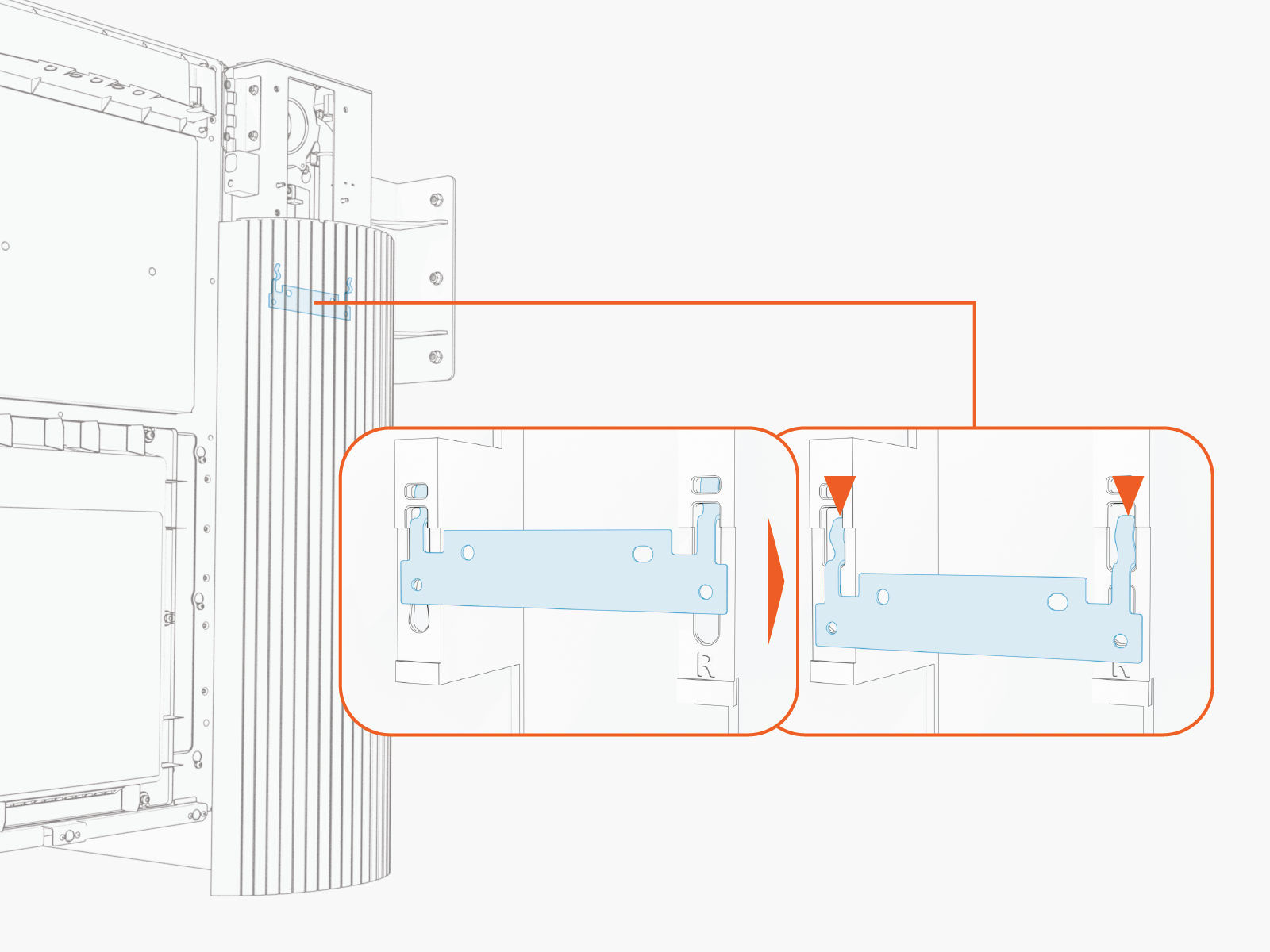
Remove Side Panel
If not already done, remove side panels from the Power Link 2000.
-
Loosen the screws (x2).
-
Slide the panel up to disengage it from hooks (x2) on the frame.
-
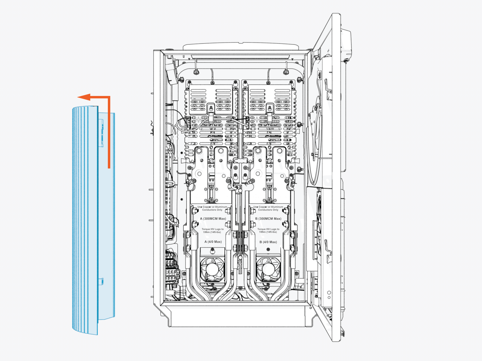
Remove the side panel. Set it aside for later reinstall.
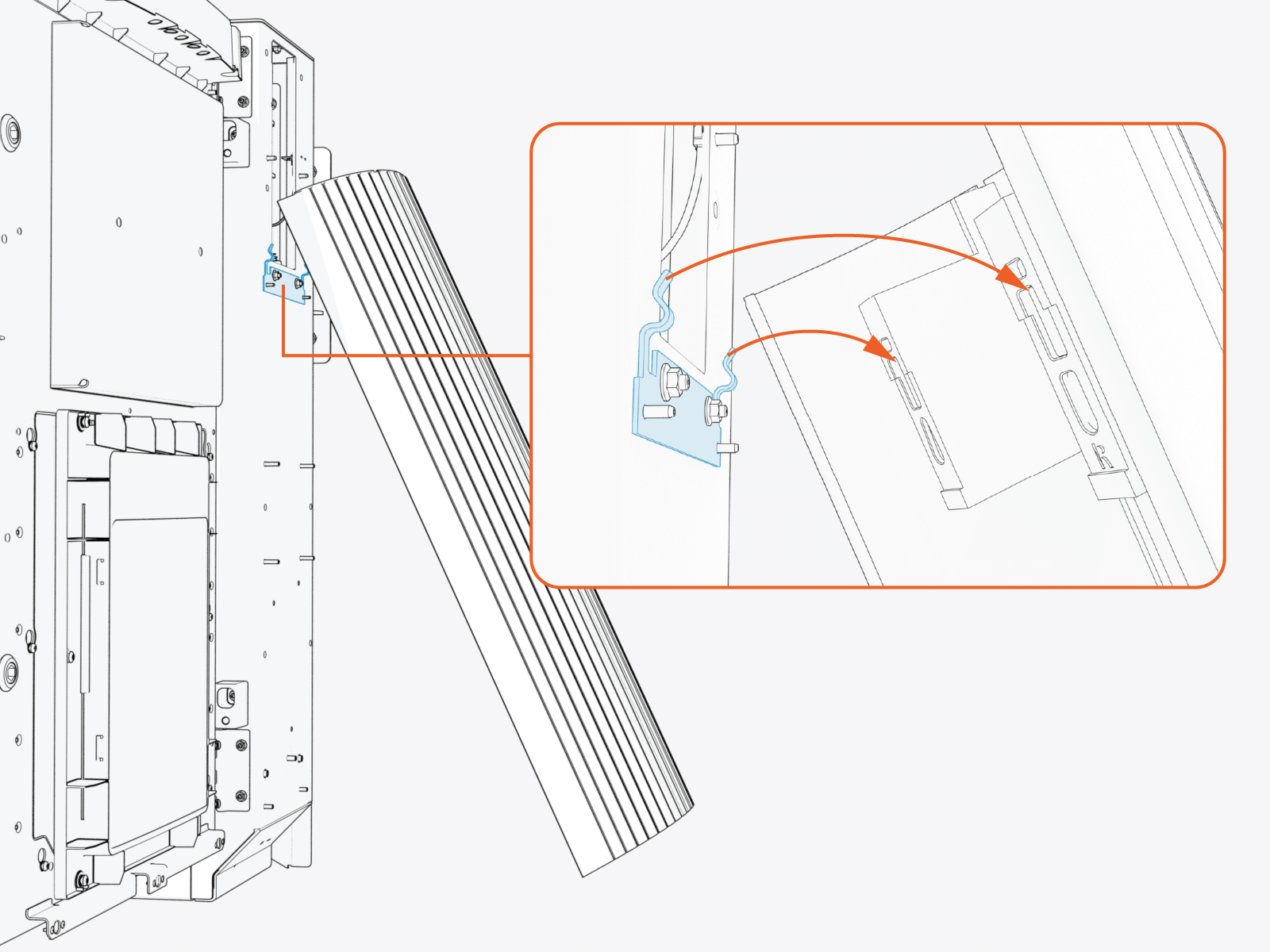
If configuring Power Link 2000 with dual charging cables, repeat the above procedure to remove the left side panel.
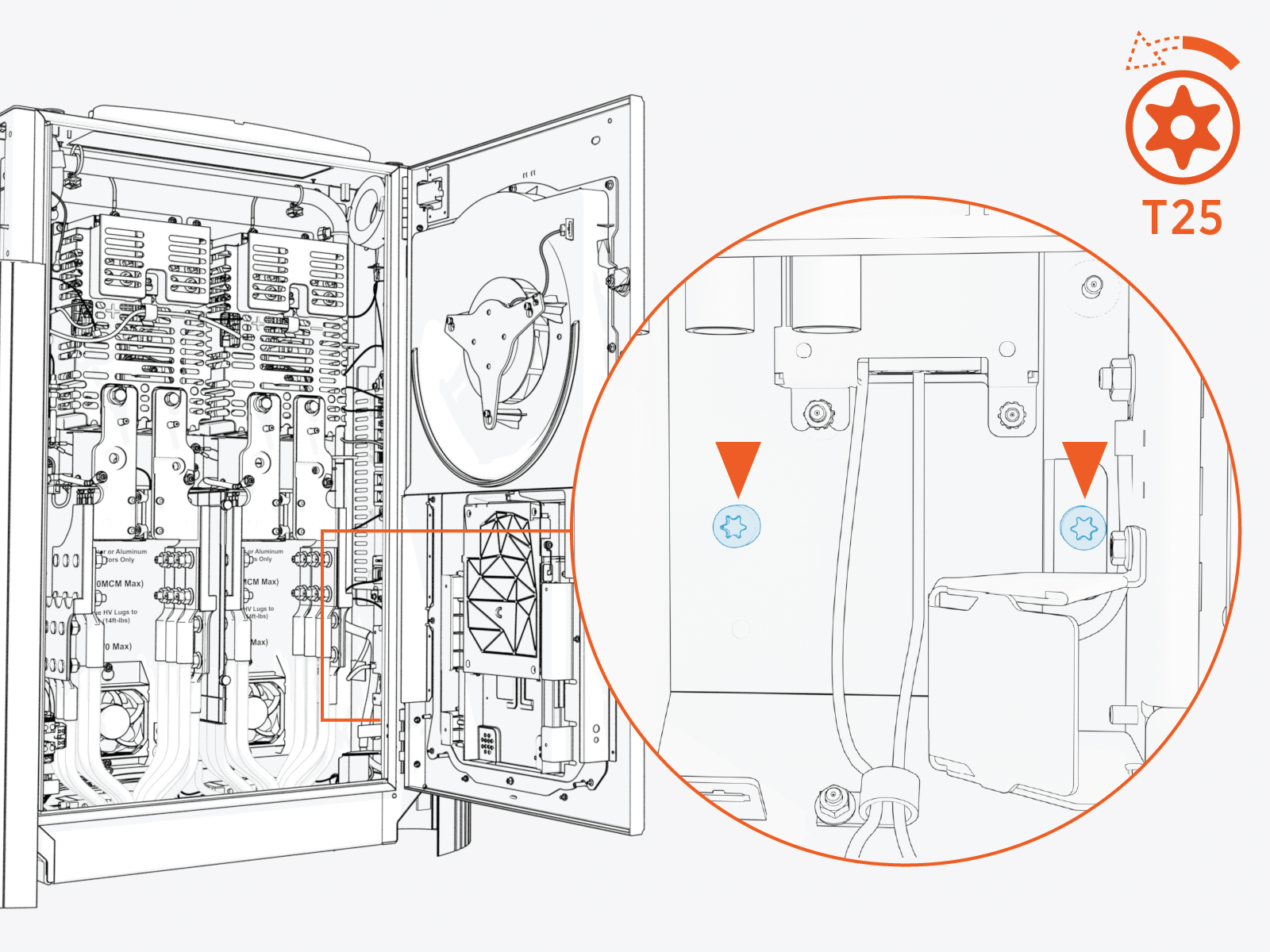
Remove HV DC Lug Landing Bus Bar Safety Cover
To remove HV DC![]() High Voltage Direct Current lug landing bus bar safety covers, complete the following steps:
High Voltage Direct Current lug landing bus bar safety covers, complete the following steps:
-
Loosen the screw (x1 per safety cover).
.")
-
Slide the safety cover up to remove it from the screw.

Install Cable Assembly
To install the cable assembly, complete the following steps:
-
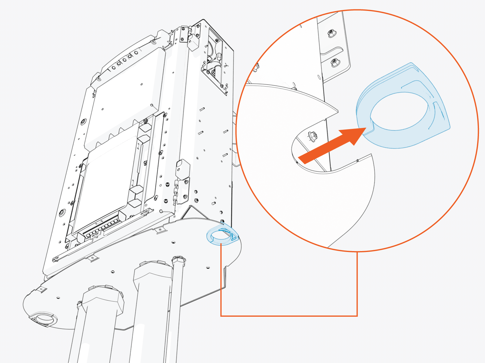
Remove the grommet from the bottom gland plate.
-
Route the cable assembly red (+) and black (-) HV DC
 High Voltage Direct Current wires through the Ferrite ring. Route other wires, such as ground (green) and Ethernet, outside of the Ferrite ring.
While routing the right side cable through the Ferrite ring, make sure that the black (-) wires are at front side and red (+) wires are at the rear side to easily maneuver and land them onto their respective poles. Conversely, while routing the left side cable, make sure that the red (+) wires are at the front side and black (-) wires are at the rear side.
 and black (-) HV DC wires through the Ferrite ring and the other wires such as ground (green) and Ethernet cable outside of the Ferrite ring.")
-
Install cable assembly onto the alignment pins (x2).
Ensure the small cables do not get pinched between the cable assembly and the Power Link 2000 frame.
.")
-
Torque the screws (x4) to 4.5 Nm (40 in-lb).
 to 4.5 Nm (40 in-lb).")
-
Route the cable through the bottom gland plate exit hole. Reinstall the grommet to the gland plate.

-
If applicable, repeat the above procedure to install the second charging cable on the left side of the enclosure.

Connect Wires
The illustrated cable connections on the left side and right side are for the left side and right side charging cables, respectively.
Connect HV Wires
To connect HV![]() High Voltage wires, complete the following steps:
High Voltage wires, complete the following steps:
|
|

-
Remove the lug nuts (x4 per red and black HV DC
High Voltage Direct Current wires; x1 per green ground wires). -
Connect red HV DC
High Voltage Direct Current wire lugs to positive (+) and black HV DC High Voltage Direct Current wires to negative (-) pole. -
Connect green ground wire lugs (x2 per charging cable) to ground stud on the frame.
-
Torque all lug nuts to 5.6 Nm (50 in-lb) and mark using a torque paint pen.
Connect LV Wires
To connect LV![]() Low Voltage wires, complete the following steps:
Low Voltage wires, complete the following steps:

-
Plug in the LV
Low Voltage wire (with labels P317-2-06 and P317-1-06) to four pin socket on the cable assembly. -
Plug in the Ethernet cable from the charging cable assembly, as illustrated above.
Reinstall HV DC Lug Landing Bus Bar Safety Cover
To reinstall the HV DC![]() High Voltage Direct Current lug landing bus bar safety cover, complete the following steps:
High Voltage Direct Current lug landing bus bar safety cover, complete the following steps:
-
Install the safety cover onto the screw (ensure that the screw is loose) and slide it down.
 and slide it down.")
-
Torque the screw to 1.7 Nm (15 in-lb).
.")
-
Tuck the internal low voltage supply wires under the wireway tab on the cover.

