Complete the Installation
To complete the installation, carry out the following steps:
Do not reconnect the power after completing the installation (after installing the covers). An Authorized Commissioning Partner will commission, power on, pinpoint, and configure Power Link 2000 after installation.
Vacuum Enclosure
Vacuum residue from the enclosure.

Reinstall Side Panels
To reinstall side panels, complete the following steps:
-
Align and install the side panel onto the hooks (x2) and alignment pins (x2) on the frame.
-
Slowly slide the side panel down to engage the hooks (x2) on the frame.
 on the frame.")
-
Align the screw holes (x2) on the rear side of the side panel with the screws (x2) inside the lower enclosure and torque them to 4.5 Nm (40 in-lb).
 behind the side panel with the screws (x2) inside the lower enclosure and torque them to 4.5 Nm (40 in-lb).")
-
If two charging cables have been installed, repeat the procedure to install the other side panel.
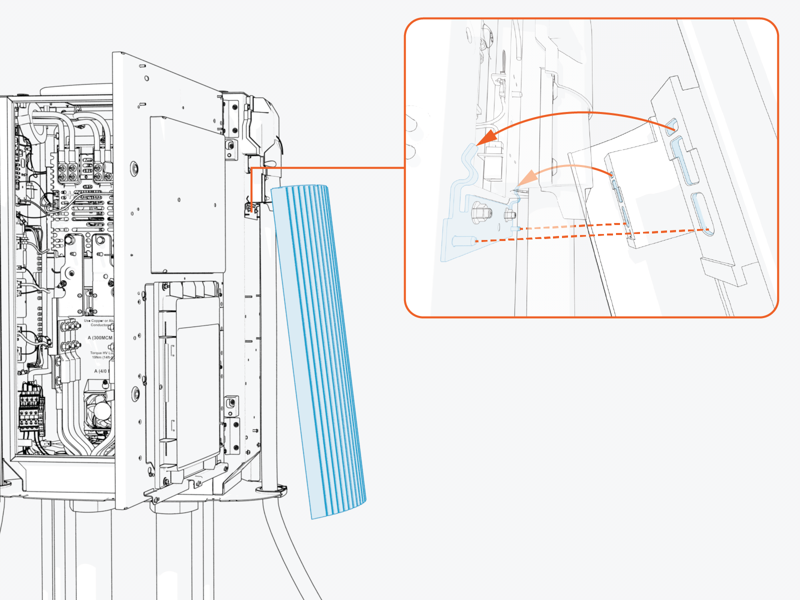
Reinstall HV DC Input Bus Bar Safety Cover
Install the cover onto the hooks (x2) and brackets (x2) and then slide it down.
 and brackets (x2) and then slide it down.")
Record MAC Address
Take a photograph of the Power Link 2000 activation QR![]() Quick Response code and MAC
Quick Response code and MAC![]() Message Authentication Code address, which can be found on the label affixed to the top of the Control and Communications Module (CCOM
Message Authentication Code address, which can be found on the label affixed to the top of the Control and Communications Module (CCOM![]() Control and Communications Module). This information is used at Power Link 2000 setup.
Control and Communications Module). This information is used at Power Link 2000 setup.
.")
Close Enclosure Doors
To close enclosure doors, complete the following steps:
-
Disengage the door stopper (x1 per upper and lower enclosure door).
.")
-
Quarter turn the door latches (x2 per upper and lower enclosure door).
.")
Install Front Cover
To install the front cover, complete the following steps:
-
Insert any one side of the cover into the groove on the side cover.

-
Gently flex the cover to insert its other side into the groove on the other side panel. At the same time, align and hook the ball studs (x3) behind the cover into the holes (x3) in a bracket on the upper door.
 behind the cover into the holes (x3) in a bracket on the upper door.")
-
Alternatively, you can hold and flex lower side of the cover slightly outward. While flexed, align the ball studs (x3) behind the cover with the holes (x3) in the bracket on the upper door and press in.
 behind the cover with the holes (x3) in the bracket on the upper door and press in.")
-
Make sure that the screws (x2) on the front upper cover are seated in their slots in the area light housing.
 on the front upper cover are seating in their slots in the area light housing.")
Install Bottom Crown
To install the bottom crown, torque captive screws (x3) to 4.5 Nm (40 in-lb).
 to 4.5 Nm (40 in-lb).")
Install Top Cap
To install the top cap, complete the following steps:
-
Align the screws (x4) and install the top cap.
-
Front screws (x2)
 and install the top cap.")
-
Rear screws (x2)
 and install the top cap.")
-
-
Make sure that the top cap sides are seated on edges on top of the side panels (x2).
.")
-
Torque the rear screws (x2) to 2.8 Nm (25 in-lb) and front screws (x2) to 1.7 Nm (15 in-lb).
 to 2.8 Nm (25 in-lb) and front screws (x2) to 1.7 Nm (15 in-lb).")
