Install Cable Management Kit
The Power Link 2000 can be installed with standard cable management kit (CMK![]() Cable Management Kit), tall CMK
Cable Management Kit), tall CMK![]() Cable Management Kit, or overhead CMK
Cable Management Kit, or overhead CMK![]() Cable Management Kit for managing different length charging cables. Depending on the space or clearance available above the Power Link 2000, the standard and tall CMK
Cable Management Kit for managing different length charging cables. Depending on the space or clearance available above the Power Link 2000, the standard and tall CMK![]() Cable Management Kit may be installed at one of two height settings, a minimum or maximum height.
Cable Management Kit may be installed at one of two height settings, a minimum or maximum height.
|
Compatible Charging Cable Length |
Installation Height |
||
|---|---|---|---|
|
Minimum |
Maximum |
||
|
Standard |
Standard length (5.8 m or 19 ft) |
2.21 m (7 ft 3 in) |
2.41 m (7 ft 11 in) |
|
Tall |
Medium length (7.6 m or 25 ft) |
2.41 m (7 ft 11 in) |
3 m (10 ft) |
|
Overhead |
- |
- |
|
Access Pre-installed CMK Mast
To access the pre-installed CMK![]() Cable Management Kit mast, complete the following steps:
Cable Management Kit mast, complete the following steps:
Power Link 2000 with LCC![]() Liquid Cooled Cable ships with a CMK
Liquid Cooled Cable ships with a CMK![]() Cable Management Kit mast preinstalled at maximum height. If the minimum height is needed, follow instructions given in this section to remove the side panels and upper rear cover of the Power Link 2000. This provides access to adjust the CMK
Cable Management Kit mast preinstalled at maximum height. If the minimum height is needed, follow instructions given in this section to remove the side panels and upper rear cover of the Power Link 2000. This provides access to adjust the CMK![]() Cable Management Kit mast position. Otherwise, skip this step.
Cable Management Kit mast position. Otherwise, skip this step.
Remove Side Panels
To remove the side panels, complete the following steps:
-
Loosen the screws (x2).
.")
-
Slowly push upper side of the side panel up to disengage it from hooks (x2) on the frame.
 on the frame.")
-
Remove the side panel and keep it aside to reinstall it later.

Remove Rear Upper Cover
To remove the rear upper cover, complete the following steps:
-
Loosen the screws (x6) to remove the rear upper cover.
 to remove the rear upper cover.")
Install Standard CMK
If the site plan calls for the Power Link 2000 to be configured with a standard CMK![]() Cable Management Kit, follow procedures in this section to install the CMK
Cable Management Kit, follow procedures in this section to install the CMK![]() Cable Management Kit.
Cable Management Kit.
Inspect the Box for Contents
Check the standard CMK![]() Cable Management Kit package for the following components:
Cable Management Kit package for the following components:
For any missing component, contact ChargePoint support at chargepoint.com/support.

-
Front cover
-
Rear cover
-
Mast
-
Single or dual swingarm assembly
-
M6 Torx screws (x5)
Install Mast
The principles and procedures outlined in this section may be used to install a mast or to adjust the height of a preinstalled CMK![]() Cable Management Kit mast.
Cable Management Kit mast.
-
Loosen the preinstalled screws if they are not loose. Hook the mast to the screws.
To install CMK
 Cable Management Kit at maximum height, the mast hooks onto eight preinstalled screws.
To install CMK
Cable Management Kit at minimum height, do the following:-
Remove these preinstalled screws (x2 from the rear of the Power Link 2000 and x2 from the front of the mast).
.")
-
Loosen and hook the mast to the remaining screws (x6).
.")
-
-
Torque loosened screws to 5.6 Nm (50 in-lb) through the screw holes at the back of the mast.
Maximum height:
 through the screw holes at the back of the mast (at minimm height).")
Minimum height:
 through the screw holes at the back of the mast (at minimum height).")
Install Swingarm Assembly
To install the swingarm assembly, complete the following steps:
-
Find the M6 Torx screws (x5) shipped in the standard CMK package.
-
Install the swingarm assembly onto the mast.

-
Install the M6 Torx screws (x5) (x4 at rear and x1 at front) and torque to 5.6 Nm (50 in-lb).
 (x4 at rear and x1 at front) and torque to 5.6 Nm (50 in-lb).")
Install Tall CMK
If the site plan calls for the Power Link 2000 to be configured with a tall CMK![]() Cable Management Kit, follow procedures in this section to install the CMK
Cable Management Kit, follow procedures in this section to install the CMK![]() Cable Management Kit.
Cable Management Kit.
Inspect the Box for Contents
Check the tall CMK![]() Cable Management Kit package for the following components:
Cable Management Kit package for the following components:
For any missing component, contact ChargePoint support at chargepoint.com/support.

-
Mast
-
Front and rear covers
-
Single or dual tall CMK
Cable Management Kit assembly -
M6 Torx screws (x8) and M10 hex screws (x4)
Install Mast
The principles and procedures outlined in this section may be used to install a mast or to adjust the height of a preinstalled CMK![]() Cable Management Kit mast.
Cable Management Kit mast.
-
Loosen the preinstalled screws if they are not loose, and hook the mast to the screws.
To install CMK
Cable Management Kit at maximum height, the mast hooks onto eight preinstalled screws.
To install CMK
Cable Management Kit at minimum height, do the following:-
Remove these preinstalled screws (x2) from the rear of the Power Link 2000.
.")
-
Loosen and hook the mast to these screws (x6).
.")
-
-
Torque loosened screws to 5.6 Nm (50 in-lb) through the screw holes at the back of the mast.
Maximum height:
 through the screw holes at the back of the mast (at maximum height).")
Minimum height:
 through the screw holes at the back of the mast (at minimum height).")
Install Tall CMK Assembly
To install tall CMK![]() Cable Management Kit assembly, complete the following steps:
Cable Management Kit assembly, complete the following steps:
-
Find the M10 hex screws (x4) shipped in the tall CMK package.
-
Install the tall CMK
Cable Management Kit assembly onto the mast.
-
Install the M10 hex screws (x4) and torque to 13.5 Nm (120 in-lb).
 and torque to 13.5 Nm (120 in-lb).")
Install Overhead CMK
If the site plan calls for the Power Link 2000 to be configured with an overhead CMK![]() Cable Management Kit, follow procedures in this section to install the CMK
Cable Management Kit, follow procedures in this section to install the CMK![]() Cable Management Kit.
Cable Management Kit.
To install the overhead CMK![]() Cable Management Kit for a pedestal-mount Power Link 2000,
the site must be equipped with a pole for mounting the overhead CMK
Cable Management Kit for a pedestal-mount Power Link 2000,
the site must be equipped with a pole for mounting the overhead CMK![]() Cable Management Kit next to each of the Power Link 2000 charging cables.
The pole must meet the design specifications given in the Express Plus Power Link 2000 Site Design Guide, available at ChargePoint Product Reference Documentation.
Cable Management Kit next to each of the Power Link 2000 charging cables.
The pole must meet the design specifications given in the Express Plus Power Link 2000 Site Design Guide, available at ChargePoint Product Reference Documentation.
Inspect the Box for Contents
Check the overhead CMK![]() Cable Management Kit package for the following components:
Cable Management Kit package for the following components:
For any missing component, contact ChargePoint support at chargepoint.com/support.

-
Mounting bracket
-
Overhead CMK
Cable Management Kit -
Hardware kit with M8 hex nuts (x4) and M6 Torx screws (x4)
Install Overhead CMK
To install the overhead CMK![]() Cable Management Kit, complete the following steps:
Cable Management Kit, complete the following steps:
-
Find the M8 hex nuts (x4) and M6 Torx screws (x4) shipped in the overhead CMK package.
-
Install the bracket onto the pole.

-
Install and torque the M8 hex nuts (x4) to 12.2 Nm (108 in-lb) to secure the bracket.
 to 11 Nm (97 in-lb) to secure the bracket.")
-
Align the overhead CMK
Cable Management Kit onto the bracket and install M6 Torx screws (x4, x2 on the left side and x2 on the right side)..")
-
Torque the screws to 3.4 Nm (30 in-lb).
.")
Install Tetherball
Standard length (5.8 m or 19 ft) charging cables come with a tetherball preinstalled onto the cable. For non‑LCC![]() Liquid Cooled Cable medium length (7.6 m or 25 ft) charging cables, a tetherball is not preinstalled onto the cable. It must be installed after installing the charging cable or while installing the CMK
Liquid Cooled Cable medium length (7.6 m or 25 ft) charging cables, a tetherball is not preinstalled onto the cable. It must be installed after installing the charging cable or while installing the CMK![]() Cable Management Kit. To install the tetherball, complete the following steps:
Cable Management Kit. To install the tetherball, complete the following steps:
-
Loosely install the tetherball onto the cable.
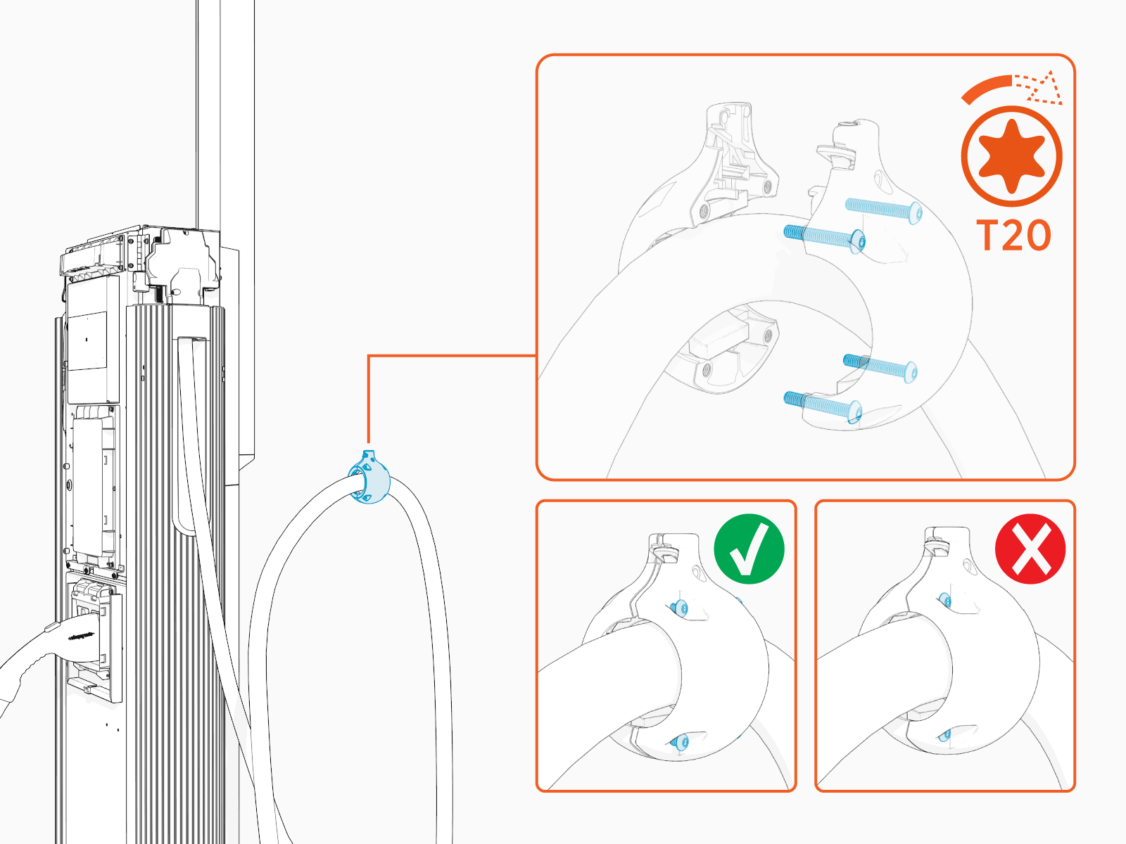
-
If necessary, slide the tetherball to a position on the cable such that the lowest point of the cable remains 25 mm (1 in) off the ground when the cable is in its stored position.

-
Torque the screws (x4) to 2.8 Nm (25 in-lb).
 to 2.8 Nm (25 in-lb).")
Suspend Charging Cable
To suspend the charging cable, complete the following steps:
-
Loosen the screw if it is not loose.

-
Align the spring tab in the tetherball with the flat notch on the tether pin. While aligned, gently push the tetherball onto the tether pin.

-
Torque the screw to 2.8 Nm (25 in-lb).
.")
-
Tug on the cable to check that it is securely attached and the swingarm or tool balancer is functioning. If you find limited motion or retraction, contact ChargePoint support at chargepoint.com/support.
-
Standard CMK
Cable Management Kit swingarm extension:
-
Tall CMK
Cable Management Kit tool balancer extension:
-
-
If two charging cables have been installed, repeat for the other side.
Install CMK Covers
To install the CMK![]() Cable Management Kit covers, complete the following steps:
Cable Management Kit covers, complete the following steps:
-
Find the front and rear covers shipped in the CMK
Cable Management Kit package. -
Insert one edge of the rear cover into one of the grooves on the rear side of the CMK
Cable Management Kit mast.
-
Gently flex the rear cover to insert its other edge into the other groove on the rear side of the CMK
Cable Management Kit mast.
-
Repeat the above steps for the front cover and ensure the following:
-
If installing covers on the standard CMK
Cable Management Kit at maximum height, make sure that the front cover is resting on the two shoulder screws on the front side of the CMK Cable Management Kit mast. is installed at maximum height, make sure that the front cover is resting on the two shoulder screws no the mast's front.")
-
If the CMK
Cable Management Kit (either standard or tall) is installed at minimum height, cut its front cover to the following height:-
Standard CMK
Cable Management Kit's front cover:
-
Tall CMK
Cable Management Kit's front cover:
-
-
